
Related Manuals for Xylem MJK 713


Summary of Contents for Xylem MJK 713
- Page 1 Manual MJK 713 Open Channel Flowmeter MJK Automation US 3.10 713 FLOW CONVERTER 1905 - SW 833062 Blokken 9 DK-3460 Birkerød Denmark +45 45 56 06 56 www.mjk.com...
- Page 2 Manual Declaration of Conformity Declaration of Conformity Konformitätserklärung Konformitetserklæring Vi, MJK Automation A/S, We, MJK Automation A/S, Wir, MJK Automation A/S, DK-3460 Birkerød, påtager os DK-3460 Birkerød, declare DK-3460 Birkerød, erklären in under our sole responsibility alleiniger Verantwortung, det fulde ansvar for at produktet that the product dass das Produkt MJK Expert Series 1400 / 3400 Pressure Level Transmitter...
-
Page 3: Table Of Contents
Measuring distances for Parshall flumes Measuring distances for Palmer & Bowlus flumes 12 Measuring distances for rectangular weirs Measuring distances for V-notch weirs Electrical mounting MJK 713 System Package 1 MJK 713 System Package 2 MJK 713 System Package 3 Cable extension Ultrasonic sensor... - Page 4 Manual Indications Menu chart Indication menus Configuration menus Function keys Flow key Q(t) Totalizer key SQ(t) Appendix Alarm key A Factory settings Power loss alarm B Trouble shooting Sample key C Technical specifications Menu key D Hardware adjustments E System Package 2 - Shuttle used as signal amplifier ®...
-
Page 5: Introduction
4B: MJK 713 model 3000: There is a risk of lethal electrical chock from terminal L-0. Be careful not to Yet MJK 713 is simple to set up and use in almost all ap- touch these while the unit is in service. -
Page 6: Product Identification
General A standard MJK 713 is delivered for two different measur- MJK 713 measures the flow in an open flume or weir ing ranges (0 - 1 ft and 0 - 3 ft). based on the level of the head in the flume. The method... -
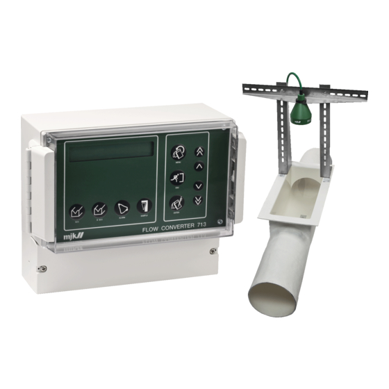
Page 7: Mechanical Mounting
MJK 713 Flowmeter Shuttle Ultrasonic Sensor ® The MJK 713 Flowmeter is in NEMA 4X enclosure and The following are extremely important when can be mounted outdoors directly on a wall or in a panel mounting the ultrasonic transmitter: using a panel mounting kit (order no. 200105). A sun It should be mounted securely. - Page 8 Manual 3: The ultrasonic sensor should be installed so that the bottom of the sensor is as close as possible to the max. height of the head but not closer than the blocking distance. Measuring range: 0 - 1’ 0 - 3’ Blocking distance: )* 16”...
-
Page 9: Measuring Distances For Parshall Flumes
Manual 4: Mount the sensor in the correct upstream distance Measuring distances for rectangular weirs from the head in the flume / weir. - with and without side contraction The distance depends on the dimension and type of flume / weir. Measuring distances for Parshall flumes Throat width b: Distance L: Throat width b: Distance L:... -
Page 10: Measuring Along A Wall Or Other Plane
Manual Measuring along a wall or other plane The spread of the ultrasonic signal The values in table 1 assume the ultrasonic signal is sent The table and illustration below show the spread of the along a smooth surface like a wall or plane without any ultrasonic signal in conjunction to the measuring distance: projections, joints, butts etc. -
Page 11: Measuring Through A Concrete Deck
Manual Measuring through a concrete deck When the ultrasonic sensor is measuring through a con- crete deck, the dimension of the opening should be made as shown below: (See table 1 for the sensor spread.) Min. diameter (D) = sensor spread + 100 % Measurement through a concrete deck with sharp edge. - Page 12 Manual Model 3100 Hydrostatic Transmitter 3: Mount the transmitter in the correct upstream The following directions should be followed when mount- distance from the contraction in the flume / weir. ing the pressure transmitter: The distance depends on the dimension and type It should be mounted securely - preferably on of flume / weir.
- Page 13 Manual Measuring distances for rectangular weirs - with and without side contraction The distance L should be between 4 to 5 times the nomi- nal width b. Measuring distances for V-notch weirs The distance L should be between 3 to 4 times the height h of the notch.
- Page 14 Manual Electrical mounting MJK 713 must not be connected to the power supply before the ultrasonic sensor / pressure transmitter is mounted and connected correctly. MJK 713 is supplied from the mains on terminal “0” and “P”. Current regulations for conductor and fuse dimensions should always be observed.
- Page 15 Black Shield )* )* This wire is connected to the cable shield. The wires are mounted according to the terminal mark- ings on the connection box PCB and on the MJK 713 respectively. Cutting the cable MJK Automation US 3.10 713 FLOW CONVERTER 1905 - SW 833062 Blokken 9 DK-3460 Birkerød...
- Page 16 )* This wire is connected to the cable shield. See section ‘Quick start’ on page 18. The wires are mounted according to the terminal mark- ings on the connection box PCB and on the MJK 713 respectively. Take care not to block or squeeze the air pressure compensation tube ➃.
- Page 17 24 hours Quick start 3b: hydrostatic sensor range When MJK 713 is powered up for the first time, a quick (applies to MJK 713 3000 / setup sequence will be initiated that will guide you System Package 2 & 3 only)
- Page 18 The max. flow range determines the range of the mA out- MJK 713 will show the following display at power-up: put. MJK 713 will calculate the max. level based on the desired max. flow for the selected primary device, and set the analog output to give out 20 mA at the max.
- Page 19 Manual Indications At the front of the flow converter, there are 4 function keys: the flow rate key Q(t), the totalizer key Σ Q(t), the Totalizer Key. See also page 20. alarm key ALARM and the sample key SAMPLE. When one of these keys is pressed one or more times, the different function menus appear.
- Page 20 24 hours (12:00:00AM). The log goes back 99 days. The arrow keys are used for accessing the log. Note, that the MJK 713 must have been in service for at least 24 hrs before the last 24 hr log will contain valid data, and at least 99 days before the full 99 days log will contain valid data.
- Page 21 Manual Alarm key Sample key The digital outputs can be configured as alarms of one of If one or more of the digital outputs are configured for the following alarm types: high flow, low flow and sensor controlling a sampler, pressing this key will give following error.
- Page 22 Manual Menu key Access denied What happens when the wrong access code is keyed in: This key gives access to the configuration menus with readout and programming of the submenus. A selection is made with the arrow keys (up or down) and It will not be possible to make changes in the setup.
- Page 23 It will still be possible to 2.1.2 Hydrostatic sensor range operate MJK 713’s normal functions and readouts. Select (MJK 713 3000 only.) function with the arrow keys and confirm with ENTER.
- Page 24 Manual 3.0 Choose primary device 3.5.2 Select decimal point for the flow values Select the type of flume/weir or flow calculation formula. Select the decimal point and 10/100/1000 multiplier for 6 options are available: Parshall flume, Palmer & Bowlus the flow points between flume, V-notch weir, rectangular weir, linearization and op- X.XXXX and XXXXX000 tional flow formula.
- Page 25 Digital output 5 (DO5) is output for an external counter. Simply enter the flow with the arrow keys and press EN- TER, and MJK 713 calculates the corres-ponding level. 4.2 Select function for DO The mA output span is set by entering the flow value For digital output 1-4 select with arrow keys between where the mA output should give out 20 mA.
- Page 26 Manual 4.7 Choose delay on signal 5.0 Analog output 0-20 / 4-20 mA The time limit for an alarm must be exceeded before a Select between 0-20 or 4-20 mA output. Select with ar- DO is activated. row keys, confirm with ENTER. The format is as follows - min:ss The maximum delay is 99 minutes and 59 seconds.
- Page 27 Manual Menu chart Indication menus Configuration menus Flow rate key Press 1 X: Average flow rate 1 hr Press 2 X: Average flow rate today Press 3 X: Average flow rate 24 hr Totalizer key Press 1 X: Totalizer 1 hr Press 2 X: Totalizer today Press 3 X: Totalizer last 24 hr In the last selection the...
- Page 28 Manual Configuration menus 2.1.1 2.1.2 MJK Automation US 3.10 713 FLOW CONVERTER 1905 - SW 833062 Blokken 9 DK-3460 Birkerød Denmark +45 45 56 06 56 www.mjk.com...
- Page 29 Manual Configuration menus 3.4.1 3.5.1 3.6.1 3.4.2 3.5.2 3.6.2 3.5.3 3.6.3 3.5.4 MJK Automation US 3.10 713 FLOW CONVERTER 1905 - SW 833062 Blokken 9 DK-3460 Birkerød Denmark +45 45 56 06 56 www.mjk.com...
- Page 30 Manual Appendix A Factory settings Basic parameters: Factory setting: Current settings: Access Code: Disabled (Code: 1111) Measurement Level: Inches Measurement Volume: Gallons Measurement Flow: Sensor distance: 30 in / 54 in* Averaging of Level: 1 sec. Range for flow: 1,000 MGD / 10.00 MGD* Flow Calculations Parshall Flume: 6’’...
- Page 31 Manual Appendix B Trouble shooting e r i n i t ¼ o i t r i f t i l i l t a t l t n i . l e . y r q i l t l u ' n i o i t .
- Page 32 Can be delivered with other cable lengths on request. Shuttle ® MJK 3400 Dimensions and accessories Ultrasonic Sensor Level Transmitter MJK 713 Flowmeter Universal bracket Sensor bracket, standard (order no. 200205) Flume mounting bracket (order no. 200220) (Max. width 21.7 in: order no. 202020 / max.
- Page 33 To carry out an adjustment, measure the dis- Changing the EPROM: tance between the 0-point and the bottom of the sensor If the MJK 713 program should be replaced you must fol- and check the setting in menu no. 0.1. low these instructions: Adjust then the current level and the range of the potenti- Turn off the power.
- Page 34 ® Shuttle must correspond to the selected level range on ® the MJK 713. Four parameters must therefore be set on the Shuttle : the measuring unit, the zero point, the level ® The measuring unit should be set to the same unit as range and the mA output zero/span.
- Page 35 MJK 713 - either 1 or 3 ft). the connection diagram on page 14 (System Package 2), MJK 713 will indicate a system error in case of a power failure or a a system error on the Shuttle ®...
- Page 36 One segment is roughly 1 mA. Mount the lid when all settings are made. See also separate SONOLEV™ 3000 manual. Note: The MJK 713 analog input must be set to 4-20 mA (factory default). MJK Automation US 3.10 713 FLOW CONVERTER 1905 - SW 833062 Blokken 9 DK-3460 Birkerød...
- Page 37 Manual Appendix F Rectangular weirs with side contractions Max. head to max. nominal flow Parshall flumes, 1 to 144 in Dimension: Max. head: (Max. nominal flow) [ft] [CFS] Dimension: Max. head: (Max. nominal flow) 1 ft w. contraction 0,50 1,060 [ft] [CFS] 1½...
- Page 38 Manual V-notch weirs Dimension: Max. head: (Max. nominal flow) [ft] [CFS] 22,5° V-notch 2,00 2,811 30° V-notch 2,00 3,824 45° V-notch 2,00 5,855 60° V-notch 2,00 8,163 90° V-notch 2,00 14,14 120° V-notch 2,00 24,49 The values stated are valid only for contractions constructed with the minimum dimensions as shown in above figure.
- Page 39 Manual MJK Automation US 3.10 713 FLOW CONVERTER 1905 - SW 833062 Blokken 9 DK-3460 Birkerød Denmark +45 45 56 06 56 www.mjk.com...
- Page 40 Manual Liability MJK Automation A/S are liable to the common rules of Danish law on product liability, however, the liability is reduced to coverage of our public liability insurance of products. To the extent where nothing else follows in lines of invariable rules of law, we are not liable for loss of profits and working deficits or other indirect losses.
Need help?
Do you have a question about the MJK 713 and is the answer not in the manual?
Questions and answers