Table of Contents
Advertisement
Advertisement
Table of Contents

Related Manuals for Xylem FLYGT MAS 711


Summary of Contents for Xylem FLYGT MAS 711
- Page 1 Installation, Operation, and Maintenance Manual MAS 711...
-
Page 3: Table Of Contents
Table of Contents Table of Contents 1 Introduction and Safety......................4 1.1 Introduction.......................... 4 1.2 Safety terminology and symbols..................4 1.3 User safety..........................5 1.4 End of life product disposal....................5 1.5 Spare parts..........................6 1.6 Warranty..........................6 1.7 Support..........................6 2 Transportation and Storage...................... 7 2.1 Inspect the delivery......................7 2.2 Storage guidelines.......................7 3 System Description........................8... - Page 4 Table of Contents 6.8.11 Set up a modem....................... 30 6.8.12 Set up a MAS network overview................31 6.8.13 Set up a MAS relay module..................31 6.9 Operator panel settings....................32 6.9.1 Change the language....................32 6.9.2 Log in and change the password................32 6.9.3 Set the date, time, unit, and MAS id.................33 6.9.4 Get the sensor information from the pump memory..........33 6.9.5 Set up a monitoring channel..................
- Page 5 Table of Contents 10 Technical Reference.......................55 10.1 Dimensions........................55 10.2 Environmental requirements..................56 10.3 IP-rating..........................56 10.4 Electrical data........................56 10.5 Approvals..........................56 10.6 The base unit panel......................56 10.7 Terminals.......................... 57 10.8 The view menu......................... 58 10.9 The setup menu....................... 60 MAS 711 Installation, Operation, and Maintenance Manual...
-
Page 6: Introduction And Safety
This includes any modification to the equipment or use of parts not provided by Xylem. If there is a question regarding the intended use of the equipment, please contact a Xylem representative before proceeding. -
Page 7: User Safety
Risk of electrical shock or burn. A certified electrician must supervise all electrical work. Comply with all local codes and regulations. All work on the product must be carried out by certified electricians or Xylem authorized mechanics. Xylem disclaims all responsibility for work done by untrained, unauthorized personnel. -
Page 8: Spare Parts
1.6 Warranty For information about warranty, see the sales contract. 1.7 Support Xylem only supports products that have been tested and approved. Xylem does not support unapproved equipment. MAS 711 Installation, Operation, and Maintenance Manual... -
Page 9: Transportation And Storage
2 Transportation and Storage 2 Transportation and Storage 2.1 Inspect the delivery Inspect the package 1. Inspect the package for damaged or missing items upon delivery. 2. Note any damaged or missing items on the receipt and freight bill. 3. File a claim with the shipping company if anything is out of order. If the product has been picked up at a distributor, make a claim directly to the distributor. -
Page 10: System Description
3 System Description 3 System Description 3.1 Product design MAS 711 is a monitoring system for large and midrange pumps. It is designed to monitor and protect a pump and to record measurement results from sensors and measurement modules. Embedded webpages in the base unit are accessible with a computer and a browser. Alarms are linked to data that is important for troubleshooting. - Page 11 3 System Description Number Part Description Pump memory It is installed inside the pump and contains information about the pump. Higher-level system It is a higher-level system that communicate with MAS711 using Modbus. MAS 711 Installation, Operation, and Maintenance Manual...
-
Page 12: Mechanical Installation
4 Mechanical Installation 4 Mechanical Installation 4.1 Install the unit on a DIN rail 1. Hook the lip at the back of the unit onto the top of the DIN rail. 2. Press the unit down until the rail clip snaps into place. MAS 711 Installation, Operation, and Maintenance Manual... -
Page 13: Electrical Installation
5 Electrical Installation 5 Electrical Installation Precautions Before starting work, make sure that the safety instructions in the chapter Introduction and Safety (page 4) have been read and understood. DANGER: Electrical Hazard Before starting work on the unit, make sure that the unit and the control panel are isolated from the power supply and cannot be energized. -
Page 14: Connect A 24-Wire Cable From A Large Pump
5 Electrical Installation Sensor Wire number Base unit terminal FLS - Leakage in stator housing Pt100 - Temperature measurement, main bearing Thermal switches - Temperature guard stator windings FLS - Leakage in junction box (14) Pt100 - Temperature measurement, stator winding phase 1 2. -
Page 15: Connect A 12-Wire Cable From A Midrange Pump
5 Electrical Installation Sensor Wire number Base unit terminal FLS - Leakage, stator housing Pt100 - Temperature measurement, main bearing Thermal switches - Temperature guard, stator windings FLS - Leakage, junction box (14) Pt100 - Temperature measurement, stator winding phase 1 Pt100 - Temperature measurement, stator winding phase 2 Pt100 - Temperature measurement, stator winding phase 3 Pt100 - Temperature measurement, support bearing... -
Page 16: Connect A 25-Wire Cable From A Midrange Pump
5 Electrical Installation – Sensor Wire number Base unit terminal FLS — Leakage, junction box (16) – VIS 10 Sensor Wire number Base unit terminal Thermal switches— Vibration sensor (16) 3. Connect the pump memory. Function Wire number Base unit terminal RS–485 B RS-485 A Supply, ground (earth) - Page 17 5 Electrical Installation VIS 10 Sensor Wire number Base unit terminal FLS -Leakage, inspection chamber Pt100 - Temperature measurement, main bearing Thermal switches - Temperature guard, stator windings FLS - Leakage, junction box (16) Pt100 - Temperature measurement stator winding phase 1 Pt100 - Temperature measurement, stator winding phase 2 Pt100 - Temperature measurement, stator winding phase 3 Pt100 - Temperature measurement, support bearing...
-
Page 18: Connect The Modbus Communication
5 Electrical Installation 5.3 Connect the Modbus communication Po we r Lo c al Re lay mo du le MRM 01 1. Pump controller 2. Power analyzer 3. Pump memory 4. Operator panel 5. Relay module Connect the applicable units to the Modbus terminals. MAS 711 Installation, Operation, and Maintenance Manual... -
Page 19: Connect The Relay Outputs
5 Electrical Installation 5.4 Connect the relay outputs 1. Connect the GO relay. 2. Connect the alarm relays, A and B. 5.5 Connect the power supply, and the additional inputs and outputs 1. Connect the base unit power supply to terminals 25 and 26. 2. -
Page 20: System Setup
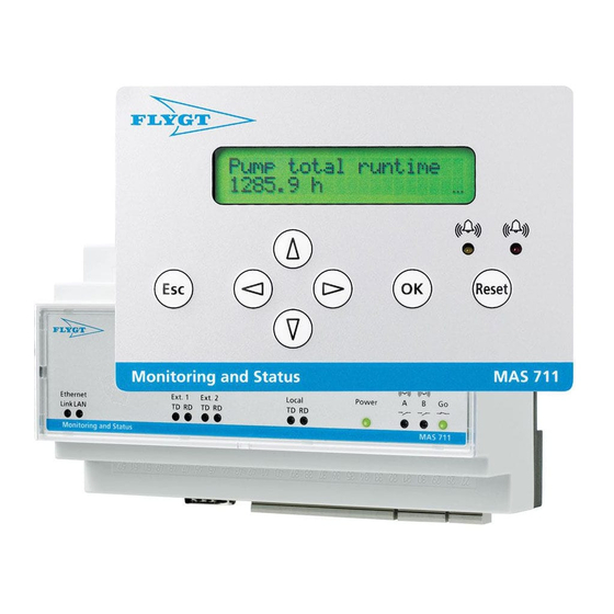
6 System Setup 6 System Setup 6.1 The operator panel Part Name Button Function Screen The screen shows control parameters and alarms. The screen shows all information in maximum two rows and 20 characters per row. Menu • Exit the current menu level. navigation •... -
Page 21: The Operator Panel Screen
6 System Setup Part Name Button Function Alarm reset Acknowledge the alarms and events button Alarm • The red LED indicates an A alarm indication • The yellow LED indicates a B alarm LEDs 6.2 The operator panel screen Number Function •... -
Page 22: Connect A Computer Directly To The Web Tool
6 System Setup 3. Set theSecurity Level to the lowest that is available. 4. Click Edit Site List..5. Click Add. 6. Add http://<IP address of the unit>/. 7. Click OK. 6.4 Connect a computer directly to the web tool The IP address of the base unit is set to the default, 10.0.48.94. - Page 23 6 System Setup 3. Click Properties. 4. Select Internet Protocol version 4 (TCP/IPv4). 5. Click Properties. 6. Set the computer IP address to 10.0.48.4. 7. Set the computer subnet mask to 255.255.255.0. 8. Click OK and close the dialog boxes. 9.
-
Page 24: Set The Ip Address With The Web Tool
6 System Setup 12.Enter the User name and Password. The default user name is config and the default password is ef56. 13.Click OK. The Quick overview view opens. 6.5 Set the IP address with the web tool 1. Connect the computer to the web tool For more information, see Connect a computer directly to the web tool (page 20). -
Page 25: Connect A Computer To The Web Tool Through A Lan
6 System Setup Save value? appears. e) Press OK. Value saved! appears. 5. Select one of the steps: Condition Action The network consists of several subnets. Edit the IP address of the router in the Ethernet Gateway 2.15.18 menu. The network has no subnets. 6. -
Page 26: Web Tool Settings
6 System Setup 6.8 Web tool settings 6.8.1 The web tool screen Number Description Mode selection: • View • Setup General pump information: • Station name • Station address • Type • Serial number Alarm indication level: • A • B Function selection: •... -
Page 27: Change The Language
6 System Setup 3. Select Set and enter the new password for operator, config, or the operator panel. 4. Click Update to confirm the new password. 6.8.3 Change the language 1. Setup 2. General configuration 3. General settings 4. Select language 1. -
Page 28: Configure The Modbus Communication
6 System Setup 2. Select Set. 3. Enter the name of the pumping station. 4. Enter the postal address of the pumping station. 5. Set the date, time, time zone, and temperature unit. Alarm limits are not automatically updated when the temperature unit is changed. 6. -
Page 29: Set Up A Monitoring Channel
6 System Setup 4. If a portable operator panel is used for a temporary connection, then turn off the operator panel communication alarm for the base unit. 5. Select the type of Power analyzer from the drop-down menu. 6. Set the Baudrate and Modbus Address to allow communication between the power analyzer and the base unit. -
Page 30: Record The Run Time And Number Of Starts
6 System Setup 6.8.7 Record the run time and number of starts 1. Click Setup > Pump current. 2. Select one of the steps: Condition Action The pump current is measured 1. Make sure that the transformer secondary rating is 1A AC. with a current transformer that 2. -
Page 31: Set The Reload Time For Alarm And Quick Overview
6 System Setup 1. Enter the Resistivity, Length of sensor cable, and Wire cross section under Calculation help for lead resistance. 2. Select Shared return lead for sensors that use a common return lead. 3. Click Calculate. The calculated value is entered automatically in the Lead resistance. 4. -
Page 32: Set Up A Modem
6 System Setup 5. Enter a maximum Email recipients. 6. Click Update. If the unit is connected through a dial-up modem connection, then changes to the modem settings must be made. For more information, see Set up a modem (page 30). -
Page 33: Set Up A Mas Network Overview
6 System Setup 6. Click Setup > General configuration > Ethernet. 7. Enter Ethernet settings a) Set the Gateway to 0.0.0.0. b) Click Update. 6.8.12 Set up a MAS network overview A MAS network overview shows key data and alarm status from other units that are connected to the same network. -
Page 34: Operator Panel Settings
6 System Setup 3. Select Activate. 4. Select the monitoring channels for the four relays on the module. 5. Select the Action priority for each relay, that is, if the relay communicates an A-alarm or a B-alarm on the specified monitoring channel. 6. -
Page 35: Set The Date, Time, Unit, And Mas Id
6 System Setup 4. Press OK. The Change password 2.4 menu opens. 5. Press OK to enter the edit mode. The first position of the password flashes. 6. Press the up and down arrow button to enter the digit and the right arrow button to move to the next position. -
Page 36: Set Up A Monitoring Channel
6 System Setup Save value? appears. g) Press OK. Value saved! appears. 2. Synchronize the pump memory and base unit. a) Go to the Pump memory sync 2.5.6 menu. b) Press OK. The Copy all from PM to MAS 2.5.6.1 menu opens. c) Press OK to confirm. -
Page 37: Check And Change The Ip Address
6 System Setup 3. Press OK to enter edit mode. The following alternatives are available: – Run input (MAS) – Current (power an.) – Current input (MAS) – None 4. Select one of the alternatives. 5. Press OK to confirm. Save value? appears. -
Page 38: Operation
7 Operation 7 Operation 7.1 Alarm levels and handling For most monitoring channels, the base unit uses two levels of alarms, A, and B. These alarm levels are available in the Setup mode: Alarm level Description It shows a serious condition. The Go interlock relay opens to stop the pump, the A alarm relay switches and the indications light up red. -
Page 39: View The Trend Diagrams
7 Operation 7.2.2 View the trend diagrams Use this function to view the sequences of events and to analyze the correlation between the measured channels. 1. Click View > Trend diagrams. Three channels are plotted simultaneously. 2. Select the channels from the Monitored channel three drop-down menus. 3. -
Page 40: Acknowledge All Active Alarms
7 Operation 2. Click a light blue alarm item. The log shows data nine minutes before and one minute after an alarm. 3. Change the Resolution drop-down menu to minutes. The logged data shows an average, that is base on one second values over a minute, four hours before the alarm trip point. -
Page 41: View A Monitoring Channel
7 Operation Condition Action Study the histogram of a monitored channel. 1. Click Histogram. 2. Select the channel from the drop-down menu. 3. Select the time period from the next drop-down menu. 4. Click Update. Study the list of ten counters that log that run 1. -
Page 42: View The Data From Other Units On The Same Network
7 Operation 2. Select the applicable steps: Condition Action Show the data plate information. Click the Data plate. Show the operator service notes. Click the Service log. Show the next service according to the operator settings. Click the Service interval. 7.2.8 View the data from other units on the same network 1. -
Page 43: Restore All The Parameters With Ftp
7 Operation 2. Click Download file for Backup all user settings, Running statistics, Service log, Data plate, etc. 3. Create a directory and save the Backup.par file. Give the file a specific name. 7.2.10 Restore all the parameters with ftp 1. -
Page 44: Edit And Upload The Selected Parameters
7 Operation 3. Click Choose file. 4. Select the backup.par file. The File chooser dialog box shows the search path of the file. 5. Click Get file content. The parameters enters the Update text box. 6. Click Update. The Update dialog box shows the update progress and the Update OK! message confirms that the update is complete. -
Page 45: Save All The Measurement Data For View In Microsoft Excel
7 Operation 4. Click Setup > General configuration > Backup. 5. Paste the 12 text lines into the Update text box. 6. Click Update. The changes take effect in a minute. 7. Click Setup > Pump info > Pump memory. 8. -
Page 46: Save All The Measurement Data To Restore The System
7 Operation 2. Select the All in the Select data log drop-down menu. 3. Click Download file. ® The database.dta file can now be viewed in Microsoft Excel 7.2.15 Save all the measurement data to restore the system 1. Click Setup > General configuration > Backup. 2. -
Page 47: Delete All The Measurement Data In A System
7 Operation 2. Enter the IP address, User name, and Password in the MAS update dialog box. 3. Click the Filename browse button. 4. Select the database file to upload. 5. Select Database under Area to update. 6. Click Upload. The database loads into the base unit. -
Page 48: Edit The Data Plate Information
7 Operation 7.2.18 Edit the data plate information 1. Click Setup > Pump info > Data plate. 2. Enter data in the Custom text box. 3. Click Update. A dialog box appears with a File saved! message. 4. Click OK. The changes are copied to the pump memory during the next automatic synchronization. -
Page 49: Copy All The Data From The Pump Memory To The Base Unit
7 Operation 2. Select the service interval functions with the applicable check box: Condition Action When a message is sent at a specified: Enter the value in the column, Next service message at. – Number of starts – Pump running time per hour –... -
Page 50: View The Alarms
7 Operation 4. To reset the value press OK . Reset value? appears. 5. Press OK. Value reset! appears. 7.3.2 View the alarms 1. Go to the Event log 1.1 menu. 2. Press OK. The first row shows the latest channel that is affected. The second row shows the type of event. -
Page 51: View The Pump Information
7 Operation 7.3.6 View the pump information 1. Go to the Dataplate info 1.2 menu. 2. Press OK. The Serial number 1.2.1 menu opens. 3. Press the right arrow button. The operator panel shows the serial number. 4. Press the down arrow button in steps. The operator panel shows the other items on the data plate. -
Page 52: Copy All The Data From The Pump Memory To The Base Unit
7 Operation 4. Press the up and down arrow button to enter a value. 5. Press OK. Save value? appears. 6. Press OK. Value saved! appears. 7.3.10 Copy all the data from the pump memory to the base unit 1. Click Setup > Pump info > Pump memory. 2. -
Page 53: Maintenance
8 Maintenance 8 Maintenance 8.1 Update the internal software 1. Contact the local esales and service representative to get the latest upgrade file. 2. Make sure that there is a connection between the computer and the base unit. 3. Close all the web browser windows that show the webpages. 4. -
Page 54: Troubleshooting
9 Troubleshooting 9 Troubleshooting 9.1 Common problems Symptom Remedy The log in fails. • Check that the user name and password are correct. The default password is ef56 for config and cd34 for operator. • If the default passwords are changed, then make sure that the new password is available. -
Page 55: Event Messages
9 Troubleshooting Symptom Remedy There is no registration of run time and number of starts. • Make sure that the function is enabled with the operator panel. For more information, ,see Record the run time and number of starts (page 34). •... - Page 56 9 Troubleshooting Event message Cause Remedy No pump memory sync There is a difference between the Manually synchronize the pump memory and pump serial number in the pump the base unit manually. memory and the base unit. Power an. com error There is a communication error with Check the: the power analyzer.
-
Page 57: Technical Reference
10 Technical Reference 10 Technical Reference 10.1 Dimensions Base unit 1. 60 mm (2.4 in) 2. 115 mm (4.5 in) 3. 86 mm (3.4 in) 4. 156 mm (6.14 in) Operator panel 1. 96 mm (3.8 in) 2. 5.5 mm (0.22 in) 3. -
Page 58: Environmental Requirements
10 Technical Reference 13.9 mm (0.35 in) 14.15 mm (0.6 in) 10.2 Environmental requirements Parameter Value Operating temperature -20°C to +60°C (-4°F to 140°F) Operating humidity Relative humidity, non-condensing: 85% 10.3 IP-rating Part Rating Base unit IP20 Operator panel, back IP20 Operator panel, front IP67... -
Page 59: Terminals
10 Technical Reference Number LED Function Description Link Ethernet connection Ethernet connection to LAN or PC for access to the web tool status Data communication indication Transmit data Modbus communication with a pump controller or PLC Receive data Transmit data Modbus communication with a power analyzer Receive data Transmit data... -
Page 60: The View Menu
10 Technical Reference Section Function Label Terminal Description Temp. (PT100) Main bearing + Temperature measurement, Pt100 Common Gnd Temperature measurement, support bearing, Pt100 Support bearing + Temperature measurement, ground (earth) Transf. input Pump current + Transformer input, 1A AC Pump current Gnd Transformer input, ground (earth) Leakage Stator housing +... - Page 61 10 Technical Reference Menu number Description 1.1.1 Alarm and event item number 1 1.1.100 Alarm and event last item (max 100 items) Data plate info 1.2.1 Pump data plate data (serial number ...) 1.2.20 Pump data plate last item (max 20 items) Pump total runtime 1.3.1 Pump trip runtime —...
-
Page 62: The Setup Menu
10 Technical Reference Menu number Description 1.15 Leakage water in oil/Leakage inspection chamber — Status Same menu structure as Temp stator ph 1 1.16 Vibration (and so forth) — Reading Same menu structure as Temp stator ph 1 1.17 Pump current Same menu structure as Temp stator ph 1 1.18 Power analyzer channel 1 —... - Page 63 10 Technical Reference Menu number Description 2.4.1 Enter new code using arrow keys. General config 2.5.1 Clock 2.5.1.1 Clock setting 2.5.2 Service interval 2.5.2.1 At number of starts 2.5.2.1.1 Service every (number of starts) 2.5.2.1.2 Present reading (number of starts) 2.5.2.1.3 Next service at (number of starts) 2.5.2.1.4...
- Page 64 10 Technical Reference Menu number Description 2.5.15 Ethernet DHCP 2.5.15.1 Active/Inactive 2.5.16 Ethernet IP address 2.5.16.1 Enter number: xxx.xxx.xxx.xxx 2.5.17 Ethernet IP netmask 2.5.17.1 Enter number: xxx.xxx.xxx.xxx 2.5.18 Ethernet gateway 2.5.18.1 Enter number: xxx.xxx.xxx.xxx 2.5.19 Ethernet DNS server 1 2.5.19.1 Enter number: xxx.xxx.xxx.xxx 2.5.20 Ethernet DNS server 2...
- Page 65 10 Technical Reference Menu number Description 2.7.2.2.1 Setting of alarm limit 2.7.2.3 High (T > y°) 2.7.2.3.1 Setting of alarm limit 2.7.2.6 Short circuit (R < 60 ohm) 2.7.3 Alarm action priority 2.7.3.1 Broken circuit (Warning/Pump stop/Off) 2.7.3.2 Very high (Warning/Pump stop/Off) 2.7.3.3 High (Warning/Pump stop/Off) 2.7.3.6...
- Page 66 10 Technical Reference Menu number Description 2.12.5.2 Very high (0 — 30s) 2.12.5.3 High (0 — 30s) 2.13 Leakage stator housing 2.13.1 Sensor 2.13.1.1 FLS/FLS10/FLS20/None 2.13.2 Alarm limits 2.13.2.1 Short circuit (I > 55 mA) 2.13.2.2 Leakage (I > 22 mA) 2.13.2.6 Broken circuit (I <...
- Page 67 10 Technical Reference Menu number Description 2.16.3.3 High (Warning/Pump stop/Off) 2.16.3.4 Low (Warning/Pump stop/Off) 2.16.3.5 Very low (Warning/Pump stop/Off) 2.16.3.6 Broken circuit (Warning/Pump stop/Off) 2.16.4 Alarm reset option 2.16.4.1 Short circuit (Manual/Automatic) 2.16.4.2 Very high (Manual/Automatic) 2.16.4.3 High (Manual/Automatic) 2.16.4.4 Low (Manual/Automatic) 2.16.4.5 Very low (Manual/Automatic)
- Page 68 10 Technical Reference Menu number Description 2.17.4.4 Low (Manual/Automatic) 2.17.4.5 Very low (Manual/Automatic) 2.17.5 Alarm delay 2.17.5.2 Very high (0 — 30s) 2.17.5.3 High (0 — 30s) 2.17.5.4 Low (0 — 30s) 2.17.5.5 Very low (0 — 30s) 2.17.7 Transformer rating (primary current) 2.18 System power 2.18.1...
- Page 69 10 Technical Reference Menu number Description 2.19.3.2 Very high (Warning/Pump stop/Off) 2.19.3.3 High (Warning/Pump stop/Off) 2.19.4 Alarm reset option 2.19.4.2 Very high (Manual/Automatic) 2.19.4.3 High (Manual/Automatic) 2.19.5 Alarm delay 2.19.5.1 Very high (0 — 30s) 2.19.5.2 High (0 — 30s) 2.20 Current unbalance Same menu structure as for Voltage unbalance (2.19) above...
- Page 72 For more information on how Xylem can help you, go to xyleminc.com Refer to www.xylemwatersolutions.com/contacts/ for contact details of your local sales and service representative.
Need help?
Do you have a question about the FLYGT MAS 711 and is the answer not in the manual?
Questions and answers