Table of Contents
Advertisement
Advertisement
Table of Contents

Related Manuals for Alienware Aurora m9700


Summary of Contents for Alienware Aurora m9700
- Page 1 User's Guide Model: M9700a – R1 Series First Edition: March 2006...
- Page 2 User's Guide NOTICE Specifications and information found in this manual are subject to change without notice. Any changes therefore will be incorporated in future editions. The manufacturer assumes no responsibility for errors or omissions in this document. TRADEMARKS Windows™ XP is the trademark of Microsoft Corporation. AMD®...
- Page 3 User's Guide The following standards are adopted throughout this manual: Notebook in boldface (with or without capitalization) refers to the notebook computer that you have purchased. Boldface type is also used to highlight important information in this document. Whenever extra caution is called for, the information will be boxed in a dark frame preceded by "Note:"...
- Page 4 User's Guide This page is left blank intentionally. Page IV...
-
Page 5: Table Of Contents
User’s Guide CHAPTER 1 - BEFORE YOU BEGIN ...1-1 HECKING XAMINING YSTEM EVEN TATUS OWER UTTON INGER PCI E XPRESS PERATING EMPERATURE <F > K CHAPTER 2 - BATTERY...2-1 ATTERY ECHARGING UESTIONS AND ATTERY AINTENANCE OWER ONSUMPTION EDUCING OWER EMOVING CHAPTER 3 - MEMORY ...3-1 EMOVING EMORY... - Page 6 Contents User's Guide This page is left blank intentionally. Page VI...
-
Page 7: Chapter 1 - Before You Begin
User's Guide Chapter 1 - Before You Begin Please read this section before you start using your computer. Checking What You Received Your notebook package should contain the following items: Note: You should keep the original factory carton and packing materials in case you need to ship the unit back for servicing. -
Page 8: Examining Your Computer
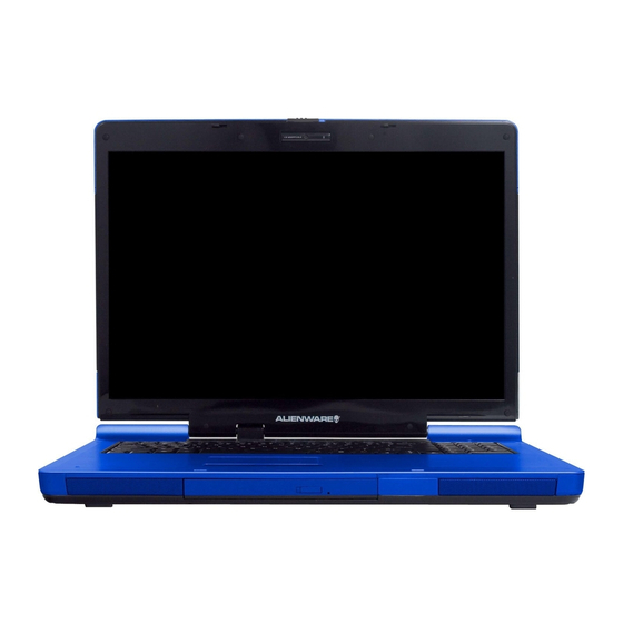
Before You Begin Examining Your Computer Before you start using your computer, you need to get acquainted with your notebook's main features and interfaces: Web Cam (Optional) LCD Latch LCD Screen Power Button Keyboard Two Click Buttons Page 1-2 Panoramic View Seven System LEDs Nine Finger-Touch Buttons Touch Pad... - Page 9 User's Guide Before You Begin Note: Press this key combination (Fn+F4) to power on and power off the optional Web Cam module. After powering on the Web Cam, you need to activate its function through Windows™. Page 1-3...
-
Page 10: Front View
Before You Begin LCD Latch Two Speakers CIR Infrared Receiver Underneath (Optional) VGA Port S-Video Out Connector Ventilation Holes RJ11 Fax/Modem Connector Audio-In Connector TV-In Connector Page 1-4 Front View Emergency Hole Eject Button ODD Drive Rear View S-Video In Connector DC-In Jack USB Connector DVI Connector... -
Page 11: Right View
User's Guide PCI Express Card Slot Media Card Slot Two USB Connectors Kensington Lock SPDIF-Out Connector Three Audio-Out Ports (Front/ Surround/ Center speakers) Microphone Jack Headphone Jack Left View Ventilation Holes RJ 45 LAN Connector IEEE1394 Connector Two HDD Doors Right View Volume Dial Ventilation Holes... -
Page 12: Bottom View
Before You Begin Compartment Door (for Memory DDR) Ventilation Holes Two HDD Doors Stereo Jack: Your headphone jack should have this type of connector as shown here. Page 1-6 Bottom View Woofer Battery Latch Battery Pack Two Types of Audio Jack User's Guide Mono Jack: Your microphone jack... -
Page 13: The Two System Leds
User's Guide The Two System LEDs The two System LEDs are closely knitted together to reflect the system and battery recharge statuses as below. Blue Blue blinking once per 1.5 seconds Amber Purple Purple blinking once per second Amber blinking once per 3 seconds Amber blinking once per second... -
Page 14: The Seven Status Leds
Before You Begin The Seven Status LEDs The Num Lock LED The LED will be lit when the keyboard is in Num Lock mode. In this mode, the embedded numeric keypads can be used. The Caps Lock LED The LED will be lit when the keyboard is in Caps Lock mode. In this mode, all characters you type are in uppercase. -
Page 15: The Power Button
User's Guide The Power Button Power Button This Power Button is programmable by user. For details on how to program this button, please refer to Power Options in the Control Panel of Windows. Note: The Power Button is located near the right side of the keyboard. For the exact location, please refer to the Panoramic View diagram in Chapter 1.2. -
Page 16: The Nine Finger-Touch Buttons
Before You Begin The Nine Finger-Touch Buttons TV Button (Optional) Press this button to run the DVD Button (Optional) Press this button to run the Music Button (Optional) Press this button to run the Next Track Button Press this button to skip to the next track/chapter of media playback. Previous Track Button Press this button to skip to the previous track/chapter of media playback. - Page 17 User's Guide Note: The system supports Windows™ MCE and Windows™ XP operating systems. Windows™ MCE supports full media center features. If you decide to use Windows™ XP and at the same time want to enjoy full media center features as supported by this notebook, you need to install software like Cyberlink™...
-
Page 18: Pci Express Card And Media Slots
Before You Begin PCI Express Card And Media Slots Media Card slot door is now inserted into the system unit. Media slot door is now taken out from the system unit. Please observe the safety measures below: • When the PCI Express Card is not inserted into the PCI Express Card slot, make sure this slot is covered by the “PCI Express Card slot door”... - Page 19 User's Guide • When no card (SD/MMC/MS Cards) is inserted into the media slot, make sure this slot is covered by the “media slot door” as supplied together with this notebook. The purpose of this “media slot door” is to prevent foreign matters from entering into the system unit through this slot, when no card is inserted.
-
Page 20: Operating Temperature
Before You Begin User's Guide Operating Temperature Operating Temperature: 10ºC to 35ºC. Page 1-14... -
Page 21: The
User's Guide The <Fn> Key The <Fn> Function Key is located near the bottom-left corner of the keyboard. This key is used together with other keys to activate certain pre-defined functions. To activate these functions, press and hold down <Fn> together with the keys described below: Sleep Switch Press this key combination (Fn+F1) to enter sleep mode.Key - Page 22 Before You Begin Mute/Un-mute Switch Press this key combination (Fn+F6) to mute and to un-mute audio volume. Decreasing Brightness Press this key combination (Fn+F7) to decrease the brightness of the LCD display. Increasing Brightness Press this key combination (Fn+F8) to increase the brightness of the LCD display.
-
Page 23: Chapter 2 - Battery
User's Guide Chapter 2 - Battery Battery Pack Your notebook is equipped with a high-energy rechargeable Lithium Ion (Li-Ion) battery pack. Battery life will vary depending on the product configuration, product model, applications loaded on the product, power management settings of the product, and product features used by the customer. -
Page 24: Questions And Answers
Battery Questions and Answers: I can feel a mild heat next to the battery pack. Is this normal? The battery will generate heat during recharging and discharging. There is a protection circuit inside the notebook to prevent overheating. You do not need to worry. -
Page 25: Battery Maintenance
User's Guide Battery Maintenance To maintain the battery pack's maximum capacity, you should occasionally let the notebook deplete its battery power completely before recharging. To carry out a complete depletion of the battery, disconnect the AC adapter and let your notebook consume the remaining battery power. -
Page 26: Reducing Power Consumption
Battery Reducing Power Consumption Although your notebook (together with the operating system) is capable of power conservation, there are measures you can take to reduce the power consumption: • Use the AC power whenever possible. • Lower the intensity of the LCD backlight. A very bright screen translates to higher power usage. -
Page 27: Chapter 3 - Memory
User's Guide Chapter 3 - Memory Your notebook is equipped with a configurable memory unit. The industry standard JEDEC PC3200 (DDR-400) S.O.DIMM memory module sockets are available for memory upgrade to 2048MB. The table below illustrates all the possible ways system memory can be configured. -
Page 28: Removing Memory Modules
Memory Removing Memory Modules Below is the procedure on how to remove the memory modules. Page 3-2 • Make sure the system is properly shutdown. • Flip the system upside down as shown. • Remove the battery pack as shown in Chapter 2. - Page 29 User's Guide To insert the memory modules, reverse the steps above. • Press the spring-locks sideways as shown by #1. • The second memory module will pop up as shown by #2. • Remove the second memory module as shown by #3. Memory Page 3-3...
- Page 30 Memory User's Guide This page is left blank intentionally. Page 3-4...
-
Page 31: Chapter 4 - The Hdd Drives
User's Guide Chapter 4 - The HDD Drives The Two HDD Sockets Your notebook is equipped with two sets of HDD sockets. These sockets support industry standard 2.5”/9.5mm SATA-2 Gen1i (1.5Gb/s) hard disk drives. Unless you are going to install two Windows bootable HDD drives into these sockets, there is generally no need to distinguish which socket is the primary socket and vice versa. -
Page 32: Removing The Hard Disk Drives
The HDD Drives Removing The Hard Disk Drives Below is the procedure on how to remove the hard disk drives. To insert the HDD drives, reverse the steps above. Page 4-2 • Make sure the system is properly shutdown. • Flip the system upside down as shown. -
Page 33: Appendix A - Agency Regulatory Notices
User’s Guide Appendix A - Agency Regulatory Notices Safety Instructions CAUTION: CAUTION: CAUTION: cleaning. DO NOT use liquid or sprayed detergent for cleaning. Use a clean moistened cloth. CAUTION: and should be easily accessible. CAUTION: CAUTION: fall can cause severe damage. WARNING: meant to protect the equipment from overheating. - Page 34 Appendix A CAUTION: unit to any power outlet. WARNING: CAUTION: WARNING: disconnect the equipment from the power source to avoid damage from power spikes. WARNING: shock is possible. WARNING: the equipment should be opened only through qualified service personnel. CAUTION: should be checked by an authorized technician: a.
- Page 35 User’s Guide CAUTION: BELOW -20ºC(-4ºF) OR ABOVE 60ºC(140ºF). IT MAY CAUSE DAMAGE TO THE EQUIPMENT. WARNING: storm. WARNING: the jack is specially designed for wet locations. WARNING: unless the modem/telephone line has been disconnected at the network interface. CAUTION: lines. WARNING: during an electrical storm.
- Page 36 Appendix A WARNING: EMPLOYS A LASER SYSTEM. a. To ensure proper use of this product, please read the relevant instructions carefully and retain for future reference. b. Should the unit ever require maintenance, contact your local dealer. c. Use of controls, adjustments or the performance of procedures other than those specified may result in hazardous radiation exposure.
- Page 37 User’s Guide WARNING: metal leads on the connector of the battery case. CAUTION: the wrong type of AC Adapter may cause serious damage to your notebook. CAUTION: 240V and is compatible with most international power sources. If you are unsure whether your power source is compatible, please contact the local dealer for assistance.
-
Page 38: Federal Communications Commission Notice
Appendix A Agency Notice Federal Communications Commission Notice This equipment has been tested and found to comply with the limits for a Class B digital device, pursuant to part 15 of the FCC Rules. These limits are designed to provide reasonable protection against harmful interference in a residential installation. - Page 39 User’s Guide • If this device is going to be operated in 5.15 -5.25GHz frequency range, then it is restricted to an indoor environment only. USA and Canada Safety Requirements And Notices The FCC with its action in ET Docket 93-62 has adopted a safety standard for human exposure to radio frequency (RF) electromagnetic energy emitted by FCC certified equipment.
-
Page 40: European Union Notice
Appendix A Use On Aircraft Caution Caution: Regulations of the FCC and FAA prohibit airborne operation of radio-frequency wireless devices because their signals could interfere with critical aircraft instruments. Canadian Notice This Class B digital apparatus meets all requirements of the Canadian Interference-Causing Equipment Regulations. - Page 41 User’s Guide For devices with built-in wireless equipment, the following additional standards apply: • ETSI301489-17: General Emissions for Radio Equipment • EN60950: Safety • ETSI300328-2: Technical Requirements for Radio Equipment CE Caution : Due to the fact that the frequencies used by 802.11b/802.11g wireless LAN devices may not yet be harmonized in all countries, 802.11b/802.11g products are designed for use only in specific countries or regions, and are not allowed to be operated in countries or regions other than those of designated use.
-
Page 42: Japanese Notice
Appendix A Maximum allowable EIRP 802.11b wireless LAN cards in the mainland departments of France not shown in the table above are as follows: (See the ART website at www.art- telecom.fr for information on the French overseas territories.) Frequency Ranges (MHz) 2400 –... - Page 43 User’s Guide Appendix A U.S. Regulations Governing the Use of Modems This equipment complies with Part 68 of the FCC Rules. On this equipment is a label that contains, among other information, the FCC registration number and Ringer Equivalence Number (REN) for this equipment. You must, upon request, provide this information to your telephone company.
- Page 44 Appendix A This modem is also suitable for connection to Private Automatic Branch Exchange (PABX), which return secondary proceeding indication. If this modem is to be used with a PBX which has extension wiring owned by BT, connection of the modem the PBX can only be carried out by BT; or by the authorized maintainer of the PBX unless the authorized maintainer has been given 14 days written notice that the connection is to be made by another person;...
Need help?
Do you have a question about the Aurora m9700 and is the answer not in the manual?
Questions and answers