
Related Manuals for Allen-Bradley 1771-IXHR


Summary of Contents for Allen-Bradley 1771-IXHR
- Page 1 (217) 352-9330 | Click HERE Find the Rockwell / Allen-Bradley 1771-IXHR at our website:...
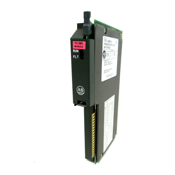
- Page 2 High Resolution Thermocouple/Millivolt Input Module Cat. No. 1771-IXHR User Manual Artisan Scientific - Quality Instrumentation ... Guaranteed | (888) 88-SOURCE | www.artisan-scientific.com...
- Page 3 Important User Information Because of the variety of uses for this product and because of the differences between solid state products and electromechanical products, those responsible for applying and using this product must satisfy themselves as to the acceptability of each application and use of this product.
-
Page 4: Table Of Contents
Table of Contents Important User Information ......Using This Manual ....... Purpose of Manual . - Page 5 Table of Contents Module Programming ......Chapter Objectives ........Block Transfer Programming .
- Page 6 Table of Contents Troubleshooting ....... . Chapter Objective ........Diagnostics Reported by the Module .
-
Page 7: Using This Manual
Chapter Using This Manual Purpose of Manual This manual shows you how to use your High Resolution Thermocouple/Millivolt input module with an Allen–Bradley programmable controller. It helps you install, program, calibrate, and troubleshoot your module. Audience You must be able to program and operate an Allen–Bradley programmable controller (PLC) to make efficient use of your input module. -
Page 8: Warnings And Cautions
Chapter 1 Chapter Title Topics Covered Warnings and Cautions This manual contains warnings and cautions. WARNING: A warning indicates where you may be injured if you use your equipment improperly. CAUTION: Cautions indicate where equipment may be damaged from misuse. You should read and understand cautions and warnings before performing the procedures they precede. -
Page 9: Related Publications
Chapter 1 Table 1.A Compatibility and Use of Data Table Use of Data Table Compatibility Catalog Number You can place your input module in any I/O module slot of the I/O chassis. You can put: two input modules in the same module group an input and an output module in the same module group. -
Page 10: Overview Of The High Resolution Thermocouple/Millivolt Input Module
Chapter 2 Chapter Overview of the High Resolution Thermocouple/Millivolt Input Module Chapter Objectives This chapter gives you information on: features of the input module how an input module communicates with programmable controllers Module Description The High Resolution Thermocouple/Millivolt input module is an intelligent block transfer module that interfaces analog input signals with any Allen–Bradley programmable controllers that have block transfer capability. -
Page 11: How Analog Modules Communicate With Programmable Controllers 2
Chapter 2 self–diagnostics and status reporting at power–up detection of open circuit if thermocouple fails automatic offset and gain calibration for each channel software calibration of all channels, eliminating potentiometers programmable filters for each group of 4 inputs X10 magnification (zoom) for millivolt mode How Analog Modules The processor transfers data to and from the module using BTW (block transfer Communicate with... -
Page 12: Accuracy
Chapter 2 When instructed by your ladder program, the processor performs a read block transfer of the values and stores them in a data table. The processor and module determine that the transfer was made without error, and that input values are within specified range. Your ladder program can use and/or move the data (if valid) before it is written over by the transfer of new data in a subsequent transfer. -
Page 13: Chapter Objectives
Chapter Installing the High Resolution Thermocouple/Millivolt Input Module Chapter Objectives This chapter gives you information on: calculating the chassis power requirement choosing the module’s location in the I/O chassis keying a chassis slot for your module wiring the input module’s field wiring arm installing the input module Before You Install Your Input Before installing your input module in the I/O chassis you must:... -
Page 14: Module Location In The I/O Chassis
Chapter 3 Add this value to the requirements of all other modules in the I/O chassis to prevent overloading the chassis backplane and/or backplane power supply. Module Location in the Place your module in any slot of the I/O chassis except for the extreme left slot. I/O Chassis This slot is reserved for processors or adapter modules. -
Page 15: Connecting Wiring
Chapter 3 CAUTION: The High Resolution Thermocouple/Millivolt Input Module uses the same keying slots as the 1771–IXE Thermocouple/Millivolt Input Module. If you are replacing a 1771–IXE with a 1771–IXHR, the ladder program must be modified to accept the new block transfer format. Connecting Wiring Connect your I/O devices to the 1771–WI field wiring arm shipped with the module (see Figure 3.2). -
Page 16: Grounding The Input Modules
Chapter 3 Figure 3.2 Connection Diagram for the 1771-IXHR Inputs – – Do not connect an input to terminals 9 and 10. They are reserved for the cold junction temperature sensor inside the wiring arm. Short circuit unused input terminals by connecting a jumper wire between the positive and negative input terminals of each unused channel. - Page 17 Chapter 3 Figure 3.3 Cable Grounding Artisan Scientific - Quality Instrumentation ... Guaranteed | (888) 88-SOURCE | www.artisan-scientific.com...
-
Page 18: Installing The Input Module
Chapter 3 Installing the Input Module When installing your module in an I/O chassis: First, turn off power to the I/O chassis: WARNING: Remove power from the 1771 I/O chassis backplane and wiring arm before removing or installing an I/O module. Failure to remove power from the backplane could cause injury or equipment damage due to possible unexpected operation. -
Page 19: Chapter Summary
Chapter 3 Chapter Summary In this chapter you learned how to install your input module in an existing programmable controller system and how to wire to the field wiring arm. Artisan Scientific - Quality Instrumentation ... Guaranteed | (888) 88-SOURCE | www.artisan-scientific.com... -
Page 20: Module Programming
Chapter Module Programming Chapter Objectives In this chapter, we describe Block Transfer programming Sample programs in the PLC–3 and PLC–5 processors Module scan time issues Block Transfer Programming Your module communicates with the processor through bidirectional block transfers. This is the sequential operation of both read and write block transfer instructions. -
Page 21: Plc-3 Program Example
Chapter 4 PLC-3 Program Example Block transfer instructions with the PLC–3 processor use one binary file in a data table section for module location and other related data. This is the block transfer control file. The block transfer data file stores data that you want transferred to the module (when programming a block transfer write) or from the module (when programming a block transfer read). - Page 22 Chapter 4 After this single block transfer write is performed, the module returns to continuous block transfer reads automatically. Artisan Scientific - Quality Instrumentation ... Guaranteed | (888) 88-SOURCE | www.artisan-scientific.com...
- Page 23 Chapter 4 PLC-5 Program Example The PLC–5 program is very similar to the PLC–3 program with the following exceptions: You must use enable bits instead of done bits as the conditions on each rung. A separate control file must be selected for each of the BT instructions. Refer to Appendix B.
-
Page 24: Module Scan Time
Chapter 4 Module Scan Time Scan time is defined as the amount of time it takes for the input module to read the input channels and place new data into the data buffer. Scan time for your module is shown in Figure 4.3. The following description references the sequence numbers in Figure 4.3. -
Page 25: Module Configuration
Chapter Module Configuration Chapter Objectives In this chapter you will read how to configure your module’s hardware, condition your inputs and enter your data. Configuring the Module Because of the many analog devices available and the wide variety of possible configurations, you must configure your module to conform to the analog device and specific application that you have chosen. -
Page 26: Input Type
Chapter 5 Input Type The thermocouple/millivolt input module accepts the following types of inputs: Table 5.A Types of Inputs Temperature Bits Input Type Input Type Range The input type is selected by setting bits in the block transfer write (BTW) file. Two different inputs can be selected. -
Page 27: Channel Alarms
Chapter 5 In the RTS mode the module scans and updates its inputs at a user defined time ∆ interval ( T) instead of the default interval. The module ignores block transfer read (BTR) requests for data until the sample time period elapses. The BTR of a particular data set occurs only once at the end of the sample period and subsequent requests for transferred data are ignored by the module until a new data set is available. -
Page 28: Configuration Block For A Block Transfer Write
Chapter 5 through 8 respectively. Word 28 activates the auto–calibration feature. Calibration is explained in chapter 7. Configuration Block for a The complete configuration block for the block transfer write to the module is Block Transfer Write defined in Table 5.C below. Table 5.C Configuration Block for the High Resolution Thermocouple/Millivolt Input Module Block Transfer Write... - Page 29 Chapter 5 E = enable bit for input types (refer to bit/word description) T = temperature scale bit (refer to bit/word description) µ µ Z = zoom enable: 0 = normal 10 V; 1 = X10 (1 Artisan Scientific - Quality Instrumentation ... Guaranteed | (888) 88-SOURCE | www.artisan-scientific.com...
-
Page 30: Bit/Word Descriptions
Chapter 5 Bit/Word Descriptions Bit/word descriptions of BTW file words 1 thru 3 (configuration), 4 thru 19 (channel alarm values), and 20 thru 27 (calibration values) are presented in Table 5.D. Enter data into the BTW instruction after entering the instruction into your ladder diagram program. - Page 31 Chapter 5 Word Bits Description µ µ µ Artisan Scientific - Quality Instrumentation ... Guaranteed | (888) 88-SOURCE | www.artisan-scientific.com...
-
Page 32: Chapter Summary
Chapter 5 Word Bits Description Table 5.E Example Zoom Settings for Word 2 Zoom Settings Bit Settings (15-08) or (07-00) µ Table 5.F Example Filter Values for Word 3 Bit Setting Filter Value (15-08) or (07-00) Chapter Summary In this chapter you learned how to configure your module’s hardware, condition your inputs and enter your data. -
Page 33: Module Status And Input Data
During normal operation, when a block transfer length of zero (0) is programmed, the 1771–IXHR will respond with a default length of 12. Table 6.A BTR Word Assignments for the 1771-IXHR Input Module Decimal Bit Artisan Scientific - Quality Instrumentation ... Guaranteed | (888) 88-SOURCE | www.artisan-scientific.com... -
Page 34: Bit/Word Descriptions
Chapter 6 Bit/Word Descriptions The complete bit/word description for the block transfer read from the module is defined in Table 6.B. Table 6.B Bit/Word Description for the 1771-IXHR Input Module Word Definition µ µ Artisan Scientific - Quality Instrumentation ... Guaranteed | (888) 88-SOURCE | www.artisan-scientific.com... -
Page 35: Chapter Summary
Chapter 6 Word Definition Chapter Summary In this chapter you learned the meaning of the status information that the input module sends to the processor. Artisan Scientific - Quality Instrumentation ... Guaranteed | (888) 88-SOURCE | www.artisan-scientific.com... -
Page 36: Module Calibration
Chapter Module Calibration Chapter Objective In this chapter we tell you how to calibrate your module. Tools and Equipment To calibrate your module you will need the following tools and equipment: Tool or Equipment Description Model/Type Available from: µ Calibrating your Input The high resolution thermocouple/millivolt input module is shipped already Module calibrated. -
Page 37: Performing Auto-Calibration
Chapter 7 Performing Auto-calibration Calibration of the module consists of applying 0.000mV across each input channel for offset calibration, and +100.000mV across each input channel for gain correction. Offset Calibration Normally all inputs are calibrated together. To calibrate the offset of an input, proceed as follows: Apply power to the module. - Page 38 Chapter 7 Table 7.A Write Block Transfer Word 28 Word/Bit 15 14 13 12 11 10 09 08 07 06 05 04 NOTE: Normally, all channels are calibrated simultaneously (bits 08–15 of word 28 are octal 0). To disable calibration on any channel, set the corresponding bit 08 through 15 of word 28.
- Page 39 Chapter 7 Figure 7.2 Applying 100.00mV for Gain Calibration After the connections stabilize (about 10 seconds), request the gain calibration by setting bit 01 in BTW word 28 and sending a block transfer write (BTW) to the module. Refer to Table 7.A. When the BTW is sent, all channels are calibrated to +100.00mV.
-
Page 40: Performing Manual Calibration
Chapter 7 Save Calibration Values If any ”uncalibrated channel” bits (bits 08–15 of BTR word 13) are set, a save cannot occur. Auto–calibration should be performed again, starting with offset calibration. If the module has a faulty channel, the remaining functioning channels can be calibrated by inhibiting calibration on the faulty channel. - Page 41 Chapter 7 Figure 7.3 Shorting Inputs for Offset Calibration Observe the input value read by the processor (word 4 of the BTR file for channel 1). It should be 0. Multiply the difference between your observed value and 0.000 by 3.0933. Determine the magnitude and sign of the required correction.
- Page 42 Chapter 7 For example, if the observed value was 17, enter –53 [(0 – 17) x 3.0933 = –53] in signed magnitude binary into the upper byte of the calibration word for that channel. Enter 10110101 in bits 15–08 of word 20. The lower byte will remain zero at this time.
- Page 43 Chapter 7 Record the input value read by the processor in the BTR file (word 4 for channel 1). Determine the percentage difference from 10000 and the sign of the correction. You can adjust the correction up to +0.19379%. A negative correction means that the reading was too high and you want to subtract a corrective amount from that reading.
-
Page 44: Chapter Summary
Chapter 7 Repeat the above steps 2 and 3 for channels 2 through 8. Initiate a write block transfer to send the corrections to the module. The input value read by the processor should now be 10000 for all channels. If the correction changes the result in the wrong direction, change the sign and reenter it. -
Page 45: Troubleshooting
Chapter Troubleshooting Chapter Objective We describe how to troubleshoot your module by observing LED indicators and by monitoring status bits reported to the processor. Diagnostics Reported by the At power–up, the module momentarily turns on both indicators as a lamp test, Module then checks for correct RAM operation... -
Page 46: Troubleshooting With The Indicators
Troubleshooting with the Table 8.A shows LED indications and probable causes and recommended Indicators actions to correct common faults. Table 8.A Troubleshooting Chart for the 1771-IXHR Input Module Indication Probable Cause Recommended Action Status Reported by the Status Reported in Word 1... - Page 47 Chapter 8 Word Explanation Status Reported in Words 2 and 3 Design your program to monitor over/under range bits, and to take appropriate action depending on your application requirements. You may also want to monitor these bits while troubleshooting with your industrial terminal. Bits 00–07 and 08–15 each represent an input for channels 1–8, respectively.
-
Page 48: Chapter Summary
Chapter 8 Status Reported in Word 13 Design your program to monitor status bits in word 13 during auto–calibration, and to take appropriate action depending on your requirements. You may also want to monitor these bits while troubleshooting with your industrial terminal. The module sets a bit (1) to indicate it has detected one or more of the following conditions as shown in Table 8.D. -
Page 49: Specifications
Appendix Specifications µ µ µ Artisan Scientific - Quality Instrumentation ... Guaranteed | (888) 88-SOURCE | www.artisan-scientific.com... -
Page 50: High Resolution Thermocouple/Millivolt Input Module Accuracy
Appendix A High Resolution The accuracy of your thermocouple readings depends on: Thermocouple/Millivolt Input module accuracy Module Accuracy lead resistance effect accuracy of the thermocouple The accuracy of the module is shown in Table A.A and Table A.B at ambient temperature (25 C) and over the temperature range (0–60 Use the calibration procedure in Chapter 7 to adjust your module to compensate... -
Page 51: Lead Resistance Compensation
Appendix A Lead Resistance Allowable Distances Compensation The open thermocouple detection circuit injects a current of approximately 7.3 nanoamps into the thermocouple cable. A total lead resistance of 1370 ohms (685 ohms one–way) cable resistance will produce 10uV of error. Source Impedance Compensation for Millivolt Inputs Source resistance causes similar errors to occur with millivolt inputs. -
Page 52: Programming Examples
Appendix Programming Examples Sample Programs for the Input The following are sample programs for entering data in the configuration words Module of the write block transfer instruction when using the PLC–3 or PLC–5 family processors. PLC-3 Family Processors Following is a sample procedure for entering data in the configuration words of the write block transfer instruction when using a PLC–3 processor. - Page 53 Appendix B When you have entered your data, press [ENTER]. If you make a mistake, make sure the cursor is over the word you desire to change. Enter the correct data and press [ENTER]. Figure B.2 Write Block Transfer for a PLC-3 Processor Press [CANCEL COMMAND].
- Page 54 Appendix B Figure B.3 Sample PLC-5 Data File (Hexadecimal Data) The above data file would configure the module as follow: ”K” thermocouples on inputs 5–8 millivolt inputs on channels 1–4 temperature scale of Celsius zoom enabled for channels 1–4 real time sampling set to a 1 second scan rate zoom center set to +70mV (46H = 70D) filter time constant = 6.4 seconds for channels 1–4 all channel alarms ON...
-
Page 55: Thermocouple Restrictions
Appendix Thermocouple Restrictions (Extracted from NBS Monograph 125 (IPTS-68)) General Following are some restrictions extracted from NBS Monograph 125 (IPTS–68) issued March 1974 on thermocouples B, E, J, K, R, S and T: B (Platinum - 30% Rhodium vs Platinum - 6% Rhodium) Type Thermocouples “The ASTM manual STP 470 [1970] indicates the following restrictions on the use of B type thermocouples at high temperatures: They should not be used in... - Page 56 Appendix C The negative thermoelement is subject to deterioration above about 871C, but the thermocouple may be used up to 1000C for short periods.” “The ASTM Manual [1970] indicates the following restrictions .. at high temperatures. They should not be used in sulfurous, reducing or alternately reducing and oxidizing atmospheres unless suitably protected with protecting tubes.
- Page 57 Appendix C “Commercial iron undergoes a magnetic transformation near 769C and <an alpha – gamma> crystal transformation near 910C. Both of these transformations, especially the latter, seriously affect the thermoelectric properties of iron, and therefore, the Type J thermocouples..If Type J thermocouples are taken to high temperatures, especially above 900C, they will lose accuracy of their calibration when they are recycled to lower temperatures.”...
- Page 58 Appendix C alters the calibration. They should also not be used in atmospheres that promote ”green–rot” corrosion (those with low, but not negligible, oxygen content).” “ASTM Standard E230–72 in the Annual Book of ASTM Standards [1972] specifies that the standard limits of error for Type K commercial thermocouples be +/–2.2C between 0 and 277C and +/–3/4 percent between 277 and 1260C.
- Page 59 Appendix C T thermocouples are less suitable for use in the subzero range than Type E thermocouples.” “Type T thermocouples are recommended by the ASTM [1970] for use in the temperature range from –184 to 371C in vacuum or in oxidizing, reducing or inert atmospheres.
- Page 60 Index Accuracy, Keying your module, Bit/Word descriptions, 1771-IXE, Module installation, Block transfer programming, Module location, Block transfer read, bit/word descriptions, 1771-IXE, BTR word assignments, 1771-IXE, Power requirements, Pre-installation considerations, Programming example Calibration PLC-3, channel offset, 1771-IXE, PLC-5, procedure for 1771-IXE, tools, Communication, how data is transferred, Real time sampling,...
- Page 61 As a subsidiary of Rockwell International, one of the world’s largest technology companies — Allen-Bradley meets today’s challenges of industrial automation with over 85 years of practical plant-floor experience. More than 13,000 employees throughout the world design, manufacture and apply a wide range of control and automation products and supporting services to help our customers continuously improve quality, productivity and time to market.
Need help?
Do you have a question about the 1771-IXHR and is the answer not in the manual?
Questions and answers