Table of Contents
Advertisement
Quick Links
Contents
This icon is used when
additional information is
available in the Isolated Analog
Input Module User Manual,
publication 1771 6.5.128.
Prevent Electrostatic
Discharge
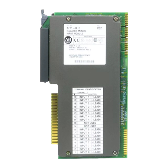
Allen-Bradley 1771-IL
Isolated Analog Input Module
(Catalog Number 1771-IL Series D)
Use this document as a guide when installing the catalog number
1771-IL/D analog input module.
To
Prevent Electrostatic Discharge
For this reference information
The isolated analog input module is sensitive to electrostatic
discharge. This module is shipped in static-shielded packaging to
guard against electrostatic discharge damage. Observe the following
precautions when handling this module.
ATTENTION: Electrostatic discharge can damage
integrated circuits or semiconductors if you touch
!
backplane connector pins. Follow these guidelines
when you handle the module:
Touch a grounded object to discharge static potential
•
Wear an approved wrist-strap grounding device
•
Do not touch the backplane connector or
•
connector pins
Do not touch circuit components inside the module
•
If available, use a static-safe work station
•
When not in use, keep the module in its original
•
static-shielded packaging
Installation Instructions
See page
Below
2
3
3
3
4
4
5
6
7
8
See page
10
11
12
13
Publication 1771 5.62 - November 1998
Advertisement
Table of Contents

Subscribe to Our Youtube Channel
Related Manuals for Allen-Bradley 1771-IL


Summary of Contents for Allen-Bradley 1771-IL
- Page 1 Installation Instructions Isolated Analog Input Module (Catalog Number 1771-IL Series D) Contents Use this document as a guide when installing the catalog number 1771-IL/D analog input module. See page This icon is used when Prevent Electrostatic Discharge Below additional information is...
- Page 2 Isolated Analog Input Module Understand Product The 1771-IL/D module can be used with any 1771 I/O chassis. Compatibility Compatibility and data table use is listed below. Use of Data Table Compatibility Catalog Input Output Read Write Addressing Number Chassis Image...
- Page 3 NOTE: The 1771 IL/D module does not supply loop power for loop powered analog sources (transmitters, transducers, etc.). Loop power must be supplied by the user. 11846 I Field Wiring Arm Cat. No. 1771 WF Allen-Bradley 1771-IL Publication 1771 5.62 - November 1998...
- Page 4 Isolated Analog Input Module Specifications Description Value Number of Inputs 8 fully isolated differential Module Location 1771 I/O rack 1 slot Input voltage ranges (nominal) +1 to +5V DC 0 to 5V DC 5 to +5V DC 10 to +10V DC Input current ranges (nominal) +4 to +20mA 0 to +20mA...
- Page 5 • CSA Class I, Division 2, Groups A, B, C, D certified • UL listed • CE marked for all applicable directives User Manual Publication 1771 6.5.128 Refer to publication 1770 4.1, Programmable Controller Wiring and Grounding Guidelines." Allen-Bradley 1771-IL Publication 1771 5.62 - November 1998...
- Page 6 Isolated Analog Input Module Differences Between The following are major differences between series levels of the Series A, Series B, Series 1771-IL isolated analog input module. C and Series D Description Series A Series B Series C and Series D...
Need help?
Do you have a question about the 1771-IL and is the answer not in the manual?
Questions and answers