
Subscribe to Our Youtube Channel
Related Manuals for Allen-Bradley 1771-KA2


Summary of Contents for Allen-Bradley 1771-KA2
- Page 1 (217) 352-9330 | Click HERE Find the Rockwell / Allen-Bradley 1771-KA2 at our website:...
- Page 2 Artisan Technology Group - Quality Instrumentation ... Guaranteed | (888) 88-SOURCE | www.artisantg.com...
- Page 3 Artisan Technology Group - Quality Instrumentation ... Guaranteed | (888) 88-SOURCE | www.artisantg.com...
-
Page 4: Table Of Contents
Table of Contents Introduction ........Description . - Page 5 Table of Contents Status Words ........General .
-
Page 6: Introduction
The unit that interfaces PLC-2 family programmable controllers to this network, and makes communication possible, is an A-B Communication Adapter Module (cat. no. 1771-KA2). (See Figure 1.1) It is a Data Highway station interface module and is used with Bulletin 1772 programmable controller processors. -
Page 7: About This Manual
(cat. no. 1775-KA) PLC-2 Family PLC-3 Mini Programmable Controller Computer 12210 About This Manual The terms “communication adapter module” and “1771-KA2” and “KA2” are interchanged throughout the manual. 1–2 Artisan Technology Group - Quality Instrumentation ... Guaranteed | (888) 88-SOURCE | www.artisantg.com... - Page 8 Chapter 1 Introduction This manual describes installation, operation, and programming necessary to use the KA2 communication adapter module. Use this manual with the other manuals and publications pertinent to your system. Table 1.A lists other available Data Highway manuals and Table 1.B lists PC manuals.
- Page 9 Court, Greendale, WI 53129. Features of a 1772-KA2 Here are some of the KA2’s features: New commands have been added to the 1771-KA2 that simplify upload and download procedures. A KA2 lets you to change (remotely) the size of the PC data table.
-
Page 10: Organization
Features of a 1771-KA2 Communication Adapter Module How the module fits into an A-B Data Highway system What a 1771-KA2 does, and the A-B PLC data processor it works with Publications available for Data Highway and PLC-2 family PCs In chapter 2 you will learn about a Data Highway station and the KA2’s role in station function. - Page 11 Chapter 1 Introduction 1–6 Artisan Technology Group - Quality Instrumentation ... Guaranteed | (888) 88-SOURCE | www.artisantg.com...
-
Page 12: Station Hardware
Data Highway Cable Trunkline Station Processor Station I/O Chassis Dropline 100 feet maximum Communication Adapter Module (cat. no. 1771-KA2) Data Highway Processor Cable (cat. no. 1771-CR) 12326 Artisan Technology Group - Quality Instrumentation ... Guaranteed | (888) 88-SOURCE | www.artisantg.com... -
Page 13: Communication Adapter Module
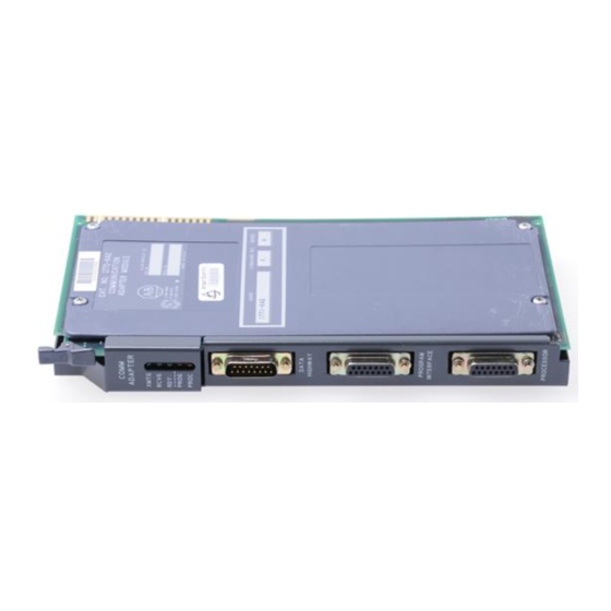
Chapter 2 Station Hardware Figure 2.2 Typical Station Configuration--Mini-PLC-2, Mini-PLC-2/05, and Mini-PLC-2/15 Controllers Data Highway Cable Trunkline Station Mini-Processor Module Station (cat. no. 1772-LV, -LS, -LSP; Dropline 1772-LN1, -LN2, -LN3) System Power Supply Connection for Programming Terminal Communication Adapter Module (cat. no. 1771-KA) Data Highway Processor Cable (cat. - Page 14 Each communication adapter module in a Data Highway installation must have a unique station number. This station number is used to address commands to the module from other stations. Figure 2.3 Communication Adapter Module (cat. no. 1771-KA2) (Side view) Indicator Connectors...
-
Page 15: Processor
Chapter 2 Station Hardware Figure 2.4 Module Connection Summary Data Highway Cable (User-Assembled) Program Panel Interconnect Cable (Cat. no. 1772-TC) “Program Panel” or “Interface” Socket on Processor Data Highway Processor Cable Industrial Terminal System (cat.no. 1771-CN, -CO, -CR) (cat. no. 1770-T1 and T2) 10863-I Data Highway Connector The upper connector of the module accepts the 15-pin Data Highway... - Page 16 Chapter 2 Station Hardware To connect any programming terminal to the PROGRAM INTERFACE connector, use a program panel interconnect cable (cat. no. 1772-TC). With a 1772-KA2 module installed, the PROGRAM INTERFACE connector substitutes for the PROGRAM PANEL connector on PLC-2/20 or PLC-2/30 processors or the INTERFACE socket on the Mini-PLC-2, Mini-PLC-2/05, or Mini-PLC-2/15.
- Page 17 Chapter 2 Station Hardware Figure 2.5 Module Indicators COMM ADAPTER Transmitting XMTG Receiving RCVG Message Ready Program Status PROG Processor Link PROC Status XMTG The green transmitting indicator turns on when the module is current master of the Data Highway. When this indicator is on, therefore, the communication adapter module is transmitting messages on the Data Highway communication link, or it is polling.
- Page 18 The section titled “Module Indicators,” in chapter 9, describes the use of indicators in troubleshooting. Switches There are 3 sets of switches on the 1771-KA2 module circuit board. These switches are beneath the small switch cover plate on the component-side cover of the module. (Refer to Figure 2.3).
- Page 19 Chapter 2 Station Hardware Module Specification Summary Table 2.A lists operating specifications for a 1771-KA2 module. Table 2.A Operating Specifications Function Compatible Power Supplies Interface entire PLC-2 family System power supply (cat. no. 1771-P1) programmable controller to the Data Highway Auxiliary power supply (cat.
-
Page 20: I/O Chassis
With PLC-2/20 and PLC-2/30 programmable controllers, use a Bulletin 1771 I/O chassis as an I/O rack. In this case, the 1771-KA2 module can be installed in any chassis slot except the one furthest left. This left-most slot must be occupied by a PLC-2 I/O adapter module (cat. no. 1771-AL or 1771-AS), shown in Figure 2.6, or a backplane jumper board assembly... -
Page 21: Power Supply
I/O ADAPTER 10864-I Power Supply A 1771-KA2 module gets its power from the backplane. It requires +5V DC at 1.2 amperes (max.). The following power supplies are compatible: System power supply (cat. no. 1771-P1) Auxiliary power supply (cat. no. 1771-P2) PLC-2 system power supply module (cat. - Page 22 Figure 2.7 1771-P1 System Power Supply Battery DC ON ALLEN-BRADLEY 10865-I When using the PLC-2/20 or PLC-2/30 processor, any of these supplies can power the I/O chassis so long as core memory is not being used. (Refer to processor manuals.) An auxiliary power supply (cat. no.
- Page 23 Chapter 2 Station Hardware Figure 2.8 PLC-2 Power Supplies 2/30 2/30 AC FUSE AC FUSE 10236-I a. PLC-2 System Power Supply Module AC FUSE 10236a-I b. PLC-2 Auxiliary Power Supply 2-12 Artisan Technology Group - Quality Instrumentation ... Guaranteed | (888) 88-SOURCE | www.artisantg.com...
-
Page 24: Cables
Chapter 2 Station Hardware Cables A 1771-KA2 module requires the following cables for installation: Data Highway/Processor cable (cat. no. 1771-CN,-CO,-CR) User-assembled Data Highway cable Figure 2.1 and Figure 2.2 show the connections made with these cables. You can order Data Highway/Processor cables in 3 lengths: 1.5 ft. - Page 25 Chapter 2 Station Hardware 2-14 Artisan Technology Group - Quality Instrumentation ... Guaranteed | (888) 88-SOURCE | www.artisantg.com...
-
Page 26: Module Installation
Chapter Module Installation General This chapter outlines procedures for preparation, installation, and connection of a 1771–KA2 module. Before performing these procedures, you should check component compatibility and the station set–up recommendations in chapter 2. Switch Settings There are 3 sets of switches on a 1771–KA2 circuit board: Write option switch assembly Station no. - Page 27 Chapter 3 Module Installation Use the tip of a ball–point or other pointed instrument to set these switches. Do not use a pencil, as lead could jam the switch. For troubleshooting purposes, we recommend that the programmer document the required switch settings for each 1771–KA2. Use form 5030, in chapter 10, to record switch settings for the module at each station.
- Page 28 Chapter 3 Module Installation ON – Enables execution of received protected commands. OFF – Disables received protected commands. Note that both an ON setting of this switch and a memory access rung are required to allow execution of received protected commands. (Memory Access rungs are described in chapter 5.) This switch does not prevent the module from receiving and executing unprotected commands from another station.
- Page 29 Chapter 3 Module Installation RECEIVE PRIVILEGED WRITE SWITCH Switch 4 determines whether the module can execute received privileged write commands. These commands can be issued only from a computer connected through a communication controller module (cat. no. 1771–KE/KF). These commands give the computer the capability to alter the user program memory of the station processor.
- Page 30 Chapter 3 Module Installation The station number switch group comprises 3 switch assemblies (SW2, SW3, SW4) on the module circuit board, as Figure 3.3 indicates. These switches determine the station number of each communication adapter module. The station number is a 3–digit octal number from 010 –077 –376 .
- Page 31 Chapter 3 Module Installation In this binary–coded octal numbering arrangement, each switch has an associated binary value: 1, 2, or 4 if set ON, 0 if set OFF. The value of each individual digit of the station number is the sum of the binary values in its corresponding switch assembly.
-
Page 32: Keying
Chapter 3 Module Installation The module is shipped with these switches set for 57.6K baud. Both switches are set ON for this communication rate. This baud rate is the intended Data Highway communication rate. CAUTION: Do not set these switches for any other baud rate. Incorrect setting of these switches may cause faulted data transmission on the Data Highway communication link. -
Page 33: Installation In The I/O Slot
Chapter 3 Module Installation Figure 3.5 Keying Band Position É É É É Keying Bands É É É É É É É É Installation In The I/O Slot Follow these procedures to install the module: Turn I/O chassis power off. (This refers to the power supply that connects to the I/O chassis at its backplane. -
Page 34: Cable Connections
Chapter 3 Module Installation Cable Connections The following cable connections are made to a communication adapter module: Data Highway cable Program panel interconnect cable (cat. no. 1772–TC) Data Highway/Processor cable (cat. no. 1771–CR, –CO,–CN) At set up, all cable connections to the module can be made with power on. After the program is up and running, however, it is safer to make connections with power off because of the possibility of noise that connecting will make. - Page 35 Chapter 3 Module Installation Figure 3.6 Data Highway Cable Connection Trunkline 1770–SC Station Connector Dropline (100 feet maximum) Communication Adapter Module (cat. no. 1771–KA2) Program Panel Interconnect Cable Connection The center connector of the communication adapter module is labeled PROGRAM INTERFACE. When the module is installed and connected to the processor, this socket connects an industrial terminal system (cat.
- Page 36 Chapter 3 Module Installation Figure 3.7 Industrial Terminal Connection Ä Ä Ä Ä Ä Ä Channel A Program Panel Interconnect Cable (cat. no. 1772-TC) 10219a-I Data Highway/Processor Cable Connector The bottom connector of a 1771–KA2 module is labeled PROCESSOR. The communication module communicates with the station processor through this connector.
- Page 37 Chapter 3 Module Installation Figure 3.8 Data Highway/Processor Cable Connection PLC-2/20 Communication Adapter Processor Module (cat.no. 1771-KA2) 2/20 Connector Labeled “Program Panel” AC FUSE Processor Connector Data Highway Processor Cable (cat.no. 1771-CR) a. Connection to PLC-2/20 or PLC-2/30 Processor Communication Adapter Mini-PLC-2/15 Module (cat.no.
-
Page 38: Commands
Chapter Commands General The primary function of a KA2 module is to transfer data to and from its station processor. The module is instructed to transfer specific units of data by user-programmed commands. The communication adapter module transmits and receives the following set of non-privileged commands: Protected write Protected bit write Unprotected write... - Page 39 Chapter 4 Commands Privileged Commands This chapter describes functions of these commands and their access to data table locations at station processors. A KA2 module can also receive privileged commands from a computer or another intelligent RS-232-C device through a 1771-KE/KF communication controller module. These privileged commands and their functions (briefly) include: Diagnostic counters reset - resets to zero all diagnostic timers &...
-
Page 40: Protected/Unprotected
Figure 4.1 illustrates this terminology. Protected/Unprotected Each 1771-KA2 module command has a prefix, either “protected” or “unprotected.” This prefix denotes memory access of the command. The distinction between these command types is: Protected commands can access (write into) only specified data table areas. -
Page 41: Write Commands
Chapter 4 Commands Figure 4.2 Protected/Unprotected Command Distinction É É É É É É É É É Memory É É É É É É É É É Word Address É É É É É É É É É É É É É É É É É É A protected An unprotected É... -
Page 42: Bit Write Commands
“Accessible Data Table Locations-PLC-2 Processors” and “Accessible Data Table Locations-PLC Processors”). On each 1771-KA2 communication adapter module, the sending and receiving of write messages can be enabled or disabled by switch settings. (Refer to chapter 3.) - Page 43 Chapter 4 Commands This first restriction simply states that no bit should be directly controlled, that is, addressed, by both an output instruction at its local station processor and a bit write command from some remote station processor. Bit write commands are generally used to set storage bits in a station processor data table.
-
Page 44: Read Command
Chapter 4 Commands The second restriction listed above applies when the destination station is a PLC-2 family PC. For these processors, when the station communication adapter module receives a bit write command it manipulates the 8-bit byte of the 16-bit memory word in which the addressed bit is located. - Page 45 Chapter 4 Commands Processor work areas Input image table Word 027 Later paragraphs describe the limitations in controlling each of these areas. Access to all other data table areas is subject to the requirements of the programmer. Processor Work Areas The processor work areas for PLC-2 family processors are addresses 000-007 and 100-107.
-
Page 46: Accessible Data Table Locations - Plc Processors
Chapter 4 Commands indicates a low-battery condition. Because of these special functions, care must be exercised in controlling word 027 with a write or bit write command. The processor does not prevent data from being written to this data table word. -
Page 47: Accessible Data Table Locations - Plc-3 Processors
Chapter 4 Commands Word 000 Reserve word 000 of the PLC processor output image table when using a KA2. This means that commands from another station must not be programmed to control word 000 or any of its bits. Accessible Data Table Locations Each PLC/PLC-2 station on a Data Highway can read from or write to - PLC-3 Processors only one specific buffer file at a PLC-3 station. -
Page 48: Accessible Data Table Locations - Plc-4 Microtrol Processors
Chapter 4 Commands The PLC/PLC-2 station can use either protected or unprotected commands to access its assigned PLC-3 file. Note, however, that the PLC/PLC-2 station cannot access its assigned file until you create and allocate that file. To create a PLC-3 file, use the CREATE command described in the PLC-3 Programming Manual (publication 1775-6.4.1). - Page 49 Chapter 4 Commands The addressing scheme is summarized in this chart: Table 4.A Internal Addressing of a PLC-4 Microtrol Controller Type of Controller Address I.D. Address Range I=Input 01-20 O=Output 01-12 X=Flags 01-32 S=Stores 01-99 Type of Controller Timer/Counter Address I.D.
- Page 50 Chapter 4 Commands Figure 4.4 Memory Map for Controller 1 Controller 1 20 inputs 1101–1120 Controller 2 Controller 3 12 Outputs Controller 4 O101–O112 Inputs, Outputs and Flags for Controller 5 each Controller on Loop Controller 6 32 Flags X101–X132 Controller 7 Controller 8 S101–S199...
- Page 51 Chapter 4 Commands address code 010 addresses the first controller - controller 1 - while address code 011 addresses the second controller - controller 2. A PLC-4 Microtrol uses a decimal addressing scheme (Table 4.A). The PLC-2 family of programmable controllers use an octal addressing scheme.
-
Page 52: Chapter Summary
Chapter 4 Commands Chapter Summary This chapter told you about the 1771-KA2’s: Station terminology Commands, protected and unprotected, reads & writes Processors’ input image table addresses, locations In chapter 5 you will learn about rungs, codes, and more commands. 4-15... - Page 53 Chapter 4 Commands 4-16 Artisan Technology Group - Quality Instrumentation ... Guaranteed | (888) 88-SOURCE | www.artisantg.com...
-
Page 54: Communication Zone Rungs
(from program to run), the changes will not affect module operation until you cycle power to the 1771-KA2 module or change the operating mode of the processor. Attempting such edits may cause unexpected communication on the Data Highway. - Page 55 Chapter 5 Communication Zone Rungs Overall Format The overall format for the communication zone of program is shown in Figure 5.1. This figure shows each type of rung that can be entered in this zone. The actual communication zone rungs for any station processor may vary significantly from those shown in Figure 5.1.
-
Page 56: Header Rungs
A header rung, as shown in Figure 5.2, indicates the beginning of the communication zone. For the communication adapter module (cat. no. 1771-KA2), the output position of this rung is always the LATCH 02707 instruction. Artisan Technology Group - Quality Instrumentation ... Guaranteed | (888) 88-SOURCE | www.artisantg.com... -
Page 57: Memory Access Rungs
Local station number Address of ERROR CODE storage word Timeout preset code The local station number is a 3-digit number switch-selected on the 1771-KA2 module. This is an octal number from 010 to 077 or from to 376 The ERROR CODE storage word is a status word in the data table of the local station processor, controlled by the communication adapter. - Page 58 Chapter 5 Communication Zone Rungs (Note that memory access rungs are not needed to allow unprotected commands; only protected commands require a memory access rung.) A memory access rung is composed of one or more memory access branches, as shown in Figure 5.3.A. In this format, a BRANCH START precedes a group of 3 GET instructions.
- Page 59 Chapter 5 Communication Zone Rungs Figure 5.3 Memory Access Example É É É É É É É É É É É É É É É É É É É É Area Memory Access É É É É É É É É É É Accessible to Boundaries in Protected Commands...
-
Page 60: Command Rungs
Chapter 5 Communication Zone Rungs For practical reasons, do not exceed the display area of the programming terminal when entering these rungs. You can program more than one memory access rung if needed. Note, however, that should multiple memory access rungs be required, you must enter them in succession in the communication zone, immediately following the header rung and before any command rung. - Page 61 Chapter 5 Communication Zone Rungs Figure 5.5 Command Rung Format Command Start Code AAAPX 02707 REFER TO FIGURES 5.6 AND 5.7 AAA – REMOTE STATION NO. P – PRIORITY INDICATOR 1 = PRIORITY MESSAGE 0 = NORMAL MESSAGE X – COMMAND TYPE 0 = PROTECTED WRITE 1 = UNPROTECTED READ 2 = PROTECTED BIT WRITE...
- Page 62 Chapter 5 Communication Zone Rungs The START bit is controlled by the program. This allows a command to be initiated only when necessary. (Programming methods for START bit control are given in chapter 7.) Command Code The second element in a command rung, the command code, identifies the following: Remote station number Priority status of the command (priority or normal)
- Page 63 Chapter 5 Communication Zone Rungs This format uses 3 GET statements. The address position of the first GET statement lists a remote station data table word. The specified command operation begins at this memory location. The second and third GET statements define the starting and ending boundaries of the data table words in the local station processor.
-
Page 64: Delimiter Rung
Chapter 5 Communication Zone Rungs Figure 5.7 Bit Command Format Area May Contain Any Legal Combination Of These Instructions: Start Command Code 027 07 FFFFF GGG GG EEEEE JJJ JJ IIIII HHH HH Branch Start (If Needed) Legend: EEEEE –] [– Set bit EEEEE in remote station data table on Set bit FFFFF in remote station data table off FFFFF... -
Page 65: Chapter Summary
Chapter 5 Communication Zone Rungs Figure 5.8 Delimiter Rung 027 07 Chapter Summary Chapter 5 was the RUNG chapter; it discussed: Communication zone rungs Communication zone of program Header rungs Memory access rungs Command rungs Start bit, command code and word command format Bit command format with EXAMINE ON, EXAMINE OFF elements In chapter 6 you will read about bit storage, fault words, and error codes. -
Page 66: Status Words
Chapter Status Words General A 1771-KA2 communication adapter module controls certain data table words specified in the local station processor by the programmer. These data table words indicate the status of command execution and provide various types of diagnostic information for start-up and troubleshooting. -
Page 67: Start/Done Word
Chapter 6 Status Words Any accessible data table words can be used as status words in the station processor. Note that the same recommendations for data table control given in section titled “Accessible Data Table Locations - PLC-2 Processors,” chapter 4, should be followed when selecting status words. That is, processor work areas, input image table words and word 027 should not be used as status words. -
Page 68: Remote/Local Fault Word
Chapter 6 Status Words REMOTE/LOCAL FAULT Word As Figure 6.1 shows, the selection of a START bit in the program not only causes a corresponding DONE bit to be controlled in the same word, but also causes REMOTE and LOCAL FAULT bits to be controlled in the next data table word. - Page 69 Chapter 6 Status Words REMOTE FAULT bits are in the upper byte of this word. A REMOTE FAULT bit is set ON when a command is received at a remote station but cannot be executed by the remote station. This may mean one of the following: Remote station processor has detected a fault in its own operation or has shut down.
-
Page 70: Error Code Storage Word
Chapter 6 Status Words Error Code Storage Word When a command cannot be carried out due to a user programming error or a discrepancy in data handled by the communication adapter module, an ERROR CODE may be written into a data table memory word. The programmer selects the error code storage word and lists it in the header rung of the communication zone of program. - Page 71 Chapter 6 Status Words The upper byte of the ERROR CODE storage word (bits 10-17) stores a 2-digit BCD value. This value gives supplemental error or fault information, depending on the type of ERROR CODE displayed. It may have one of two meanings: Reference number Counter For ERROR CODES 01-29, the upper byte stores a 2-digit reference...
-
Page 72: Chapter Summary
Chapter 6 Status Words Chapter Summary This was the WORD and CODE chapter and it discussed: START/DONE, REMOTE/LOCAL FAULT bit storage REMOTE/LOCAL fault word Error code storage word (Error code list is in Appendix A.) Chapter 7 continues discussion about command initiation, control bits, fault words, and monitoring. - Page 73 Chapter 6 Status Words Artisan Technology Group - Quality Instrumentation ... Guaranteed | (888) 88-SOURCE | www.artisantg.com...
-
Page 74: Command Initiation, Execution, And Monitoring
Normal Operation Command execution begins when the user program turns a START bit ON, normally with a LATCH instruction. The 1771-KA2 communication adapter module detects the ON state of this bit and then begins the operations necessary to format and transmit a command message. - Page 75 Chapter 7 Command Initiation, Execution, and Monitoring Figure 7.1 shows the timing of START and DONE bits for a command. The significance of START/DONE bit status is summarized in Table 7.A. Figure 7.1 START/DONE Bit Timing - Normal Operation É É É É É É É É É É É É É É É É Start É...
- Page 76 Chapter 7 Command Initiation, Execution, and Monitoring Faulty Operation Certain fault conditions can prevent normal reception and execution of commands by the receiving station. To indicate the source of such fault conditions, the KA2 controls REMOTE and LOCAL FAULT bits at the station processor.
-
Page 77: Controlling The Start Bit
Monitoring Recall that the START bit is program-controlled. The REMOTE/LOCAL FAULT bits, meanwhile, are controlled by the 1771-KA2 module. The programmer must keep this relationship in mind when planning START bit control and FAULT bit monitoring in the ladder-diagram program. - Page 78 FAULT bit response causes the program to re-initiate command execution. (This type of programmed re-try is not to be confused with the re-try procedure of the 1771-KA2 module itself; transparent to user programming, the module automatically attempts several re-tries of a message before it sets a FAULT bit.
- Page 79 START bit in the second rung. In the first rung, the START bit is LATCHED again after the communication adapter module resets the FAULT bit. (As Figure 7.2 shows, the 1771-KA2 module resets a FAULT bit only after the START bit has been turned OFF.)
- Page 80 Chapter 7 Command Initiation, Execution, and Monitoring Even though the FAULT bits are continually reset with this method, their usefulness must not be overlooked. The section titled “REMOTE/FAULT Bit Monitoring” outlines a useful method to monitor FAULT bits and control an output indicator based on FAULT bit status. In some applications, it may be useful to send a command continuously between stations.
- Page 81 Chapter 7 Command Initiation, Execution, and Monitoring Figure 7.4 Transition-Initiated Command Input Compare Transition 01111 11111 02000 Rung 1 Input Compare 11111 01111 Input Compare 11111 01111 Rung 2 Transi– Remote Local tion Fault Fault Start 02000 03312 03302 03212 Rung 3 Done Start...
- Page 82 Chapter 7 Command Initiation, Execution, and Monitoring In this example, a storage bit, called the “transition” bit, is manipulated to control the sending of the command. This bit is LATCHED whenever a transition of input 11111 is detected, UNLATCHED only when the DONE bit is set ON.
- Page 83 Chapter 7 Command Initiation, Execution, and Monitoring Figure 7.5 Timer-Initiated Command Done 032 02 PR 010 AC 000 Start Timed Bit 032 12 046 15 Done Start 032 02 032 12 Local Fault 033 02 Remote Fault 033 12 In this example, timed bit 04615 is used to initiate the command at every preset interval, 10 seconds.
- Page 84 Chapter 7 Command Initiation, Execution, and Monitoring executed, but also point to the general type of fault condition that prevented command completion. The user program must monitor the REMOTE and LOCAL FAULT bits for each command. The recommendations of this section describe two methods for monitoring FAULT bits and using these bits to signal a fault condition.
- Page 85 Chapter 7 Command Initiation, Execution, and Monitoring Figure 7.6 FAULT Bit Diagnostic Rungs (Single Command Example) Output Indicator Remote Fault 03310 01000 Local Fault 033 00 Output Indicator Done 03200 010 00 The method of Figure 7.6 can be extended to monitor multiple commands from a station, controlling multiple output indicators as necessary.
- Page 86 Chapter 7 Command Initiation, Execution, and Monitoring Figure 7.7 FAULT Bit Diagnostic Rungs (Multiple Commands Example) Local Fault Rung 1 Status 055 00 033 07 033 06 033 05 033 04 033 03 033 02 033 01 033 00 Remote Fault Rung 2 Status 055 01...
-
Page 87: Timeout Preset Value
Use of FAULT bits in start-up and troubleshooting procedures is described in chapter 9. Timeout Preset Value In addition to its REMOTE/LOCAL FAULT bit control, a 1771-KA2 module also provides an automatic timer for monitoring command completion. While it functions automatically during module operation, the timer uses a preset value entered in the user program. - Page 88 Chapter 7 Command Initiation, Execution, and Monitoring enters the value 37 in the lower byte of the ERROR CODE storage word of the header rung. Figure 7.8 Timeout Preset Significance Code Header Rung (Representation) Code ”37” Entered Timeout Preset Interval, if Timeout Occurs Within this Period Done or Fault Bit Expected...
- Page 89 Chapter 7 Command Initiation, Execution, and Monitoring Timeout preset monitoring is intended as a backup for the other communication monitoring functions of the module. It is designed to signal any condition where the module has not completed its communication with another station or detected some fault condition within a short time.
- Page 90 Mini-PLC-2 Programmable Controller. You can disable the timeout by using the value 010. User-Programmed Timeout (Optional) The automatic timeout of a 1771-KA2 communication adapter module has a backup function. This automatic monitoring routine continuously checks module interaction with other Data Highway stations, timing the execution of commands.
- Page 91 Chapter 7 Command Initiation, Execution, and Monitoring to detect such a condition; the simplest of these methods uses an ON-DELAY timer. Figure 7.9 shows typical rungs that can be programmed for this purpose. Figure 7.9 Typical User-Programmed Timeout Start Done 032 02 032 12 PR 100...
-
Page 92: Chapter Summary
Chapter 7 Command Initiation, Execution, and Monitoring communication adapter module. (REMOTE and LOCAL FAULT bits at other stations indicate the same types of faults that can be detected using a user-programmed timeout.) A programmed timeout would not be necessary for each command from a station. Instead, a single command at each station can be monitored in this manner. - Page 93 Chapter 7 Command Initiation, Execution, and Monitoring 7-20 Artisan Technology Group - Quality Instrumentation ... Guaranteed | (888) 88-SOURCE | www.artisantg.com...
-
Page 94: Station Interfacing
Chapter Station Interfacing General To execute commands, a 1771-KA2 communication adapter module at one station interacts with all other stations interface modules on the Data Highway. This chapter describes this interaction of station interface modules. Because much of this interaction is transparent to user programming, the information given here is largely for background. - Page 95 Chapter 8 Station Interfacing Mastership A Data Highway cable links as many as 64 stations. Because this cable has a single pair of wires, only one station can transmit at a time. When a station interface module gains control of this data link to transmit messages, that station has mastership.
- Page 96 As soon as the communication module attains mastership, it sends its command and reply messages (up to a maximum number--16 for the 1771-KA2). After the module sends its command and reply messages, it transmits a sequence of polling messages. By this sequence, it selects the next station to be master of the Data Highway communication link.
- Page 97 Chapter 8 Station Interfacing The reply message is an automatic function of communication adapter module operation, transparent to the user program. To send a reply message, a station must have mastership. Acknowledgement When a station receives a message addressed to it, whether it is a command or reply message, the receiving station sends an acknowledgement.
-
Page 98: Commands From A Computer
A communication adapter module can execute commands from a computer connected through a communication controller module (cat. no. 1771-KE or -KF). The command set of the computer includes the command set of the 1771-KA2 module: Protected write Protected bit write... - Page 99 Enter upload mode (New for 1771-KA2) Exit upload/download mode Diagnostic read Diagnostic counters reset Set data table size (New for 1771-KA2) Diagnostic Status Privileged commands give the computer the capability to read from or write into the entire processor memory. This includes both data commands and user program areas.
- Page 100 PLC-2 family processor. Indications of Upload, Download (Earlier revisions) If you are using a revision of the 1771-KA2 module before revision D, or a revision of the 1770-T3 terminal before revision G, and are uploading or...
- Page 101 DOWNLOAD COMPLETED - ALL FORCES CLEARED displays a mode select menu When you connect a 1770-T3 terminal (revision G) to a 1771-KA2 module (series A, revision D) and perform program uploads when the 1770-T3 terminal is not in PLC-2 mode, the terminal displays a mode...
-
Page 102: Chapter Summary
Chapter Summary This chapter dealt with interfacing and interaction of a 1771-KA2 with its station and other stations on a Data Highway. This chapter covered: Floating master format Mastership of a Data Highway... - Page 103 Chapter 8 Station Interfacing 8-10 Artisan Technology Group - Quality Instrumentation ... Guaranteed | (888) 88-SOURCE | www.artisantg.com...
-
Page 104: Start-Up And Troubleshooting
The methods described in this chapter can be used to test any station that contains a Bulletin 1772 programmable controller and a 1771-KA2 communication adapter module. Methods for start-up and troubleshooting of other processors are described in other manuals. - Page 105 Chapter 9 Start–up and Troubleshooting Figure 9.1 Module Indicator Combinations Station Address Ready to Receiving a is 377 Transmitting a Send Message (Illegal) Message Message COMM COMM COMM ADAPTER ADAPTER ADAPTER Transmitting Receiving Ready Both Program Status Flashing Processor Link Status Alternately COMM COMM...
- Page 106 (These rungs are described in chapter 5.) A 1771-KA2 module checks the communication zone rungs of program at power-up and whenever the mode select switch on the processor is turned from PROG to TEST or RUN. It also checks these rungs after any...
- Page 107 Chapter 9 Start–up and Troubleshooting Processor troubleshooting is described in the appropriate Assembly and Installation or User’s Manual for each controller. After the processor fault is corrected, the module automatically rechecks its communication with the processor and checks the communication zone rungs.
- Page 108 Chapter 9 Start–up and Troubleshooting Table 9.A SEARCH Functions - Industrial Terminal Key Sequence Response Positions cursor on the following program instruction. Positions cursor on preceding program instruction. Displays previous rung. Displays following rung. Displays first rung of program. Search Search Displays END statement of program.
- Page 109 Chapter 9 Start–up and Troubleshooting Note that this status indication is provided in both RUN and TEST modes. In the PROGRAM LOAD (or PROG) mode, however, intensity of a displayed instruction indicates cursor position. Figure 9.2 illustrates the significance of an intensified instruction for both the industrial terminal and the PLC program panel.
- Page 110 Chapter 9 Start–up and Troubleshooting FORCE ON Function The FORCE ON function, available with each of the 3 programming terminals, can be a useful troubleshooting tool. When used in conjunction with the optional test rungs of section titled “Test Rungs (Optional),” this function controls the initiation of each command programmed at a station.
- Page 111 Chapter 9 Start–up and Troubleshooting Figure 9.3 REMOTE/LOCAL FAULT Bit Significance Processor Local Fault Possible Sources: Disconnected data highway cable 2/20 Power off at receiving station interface module Unused remote staiton no. address AC FUSE Station interface moduel at local or remote station has disconnected itself as a result of link monitoring Automatic timeout at sending...
- Page 112 Chapter 9 Start–up and Troubleshooting Appendix A lists each ERROR CODE and its meaning. Figure 9.4 Header Rung Error Code Storage Word Local Location Station No. Timeout Preset Code 02707 Test Rungs (Optional) For start-up and troubleshooting testing, you must have some means for control of each START bit.
- Page 113 Chapter 9 Start–up and Troubleshooting Optional test rungs are shown in Figure 9.5. Within this ZCL area, the START bit is unconditionally LATCHED ON (rung 2) and UNLATCHED when the DONE bit is ON (rung 3). In rung 1, a single input image table bit is the condition for the ZCL area.
- Page 114 Chapter 9 Start–up and Troubleshooting These rungs send the command continuously, as long as the ZCL area is enabled. As a quick check of this continuous command execution and completion, another rung can be added to the test rungs within the ZCL area.
-
Page 115: Start-Up Procedures
Chapter 9 Start–up and Troubleshooting A ladder-diagram printout can be generated on a compatible data terminal, such as a teletype or other line printer. Forms for programmer documentation are described in chapter 10. Start-up Procedures A careful start-up procedure is essential to proper Data Highway operation. - Page 116 Chapter 9 Start–up and Troubleshooting Overall Approach In start-up testing, it is best to limit the number of things happening at one time. By carefully limiting the scope of start-up testing to a small number of variables, the source of a problem is more readily detected. Paired Testing In the early stages of Data Highway testing, limit the size of the group of stations being tested.
- Page 117 Chapter 9 Start–up and Troubleshooting Increasing the Group Size Once paired testing has been completed, execution of each command has been verified. At this point, the size of the tested group of stations is increased and station interaction of this larger group can be monitored. For this phase of testing, the same checks outlined in sections titled “Testing the Sending Station”...
- Page 118 Chapter 9 Start–up and Troubleshooting The ERROR CODE storage word is listed in the header rung of the communication zone of program. The significance of the ERROR CODE storage word is described in section titled “Testing the Receiving Station.” Correct the communication zone rungs as indicated by the ERROR CODE.
- Page 119 Chapter 9 Start–up and Troubleshooting Sample test rungs are shown in Figure 9.5. The following steps outline the procedures for programming these rungs for testing. With the programming terminal connected, follow these procedures: Display the END (of program) statement. The key sequence that displays this part of the program is as follows: [SEARCH] [ ] Turn the processor mode select switch to the PROGRAM or PROG...
- Page 120 Chapter 9 Start–up and Troubleshooting With the START bit energized, proceed to the monitoring checks of the paragraph entitled “Monitoring DONE and REMOTE/LOCAL FAULT Bits.” Once these checks have been completed, the next START/DONE bit addresses can be entered in the test rung for testing of the next command.
-
Page 121: Troubleshooting
Chapter 9 Start–up and Troubleshooting Testing the Receiving Station The receiving station is checked with the sending station for one purpose--verification of data transfer. Although this procedure may be time-consuming, it is essential in initial start-up testing and for testing whenever a command is added at a station. - Page 122 Chapter 9 Start–up and Troubleshooting REMOTE/LOCAL FAULT Indicator ON As recommended in chapter 7, some indicator must be controlled by the status of the REMOTE and LOCAL FAULT bits at each station processor. Should this indicator go ON, connect and initialize a programming terminal and follow these procedures to isolate the source of the fault condition.
- Page 123 Chapter 9 Start–up and Troubleshooting on the program panel or industrial terminal, observe the status indicators of the terminal carefully. Due to CRT delay time, the intensity of an EXAMINE OFF instruction, which shows its status, may not change as rapidly as does the actual ON/OFF status of the FAULT bit.
- Page 124 Chapter 9 Start–up and Troubleshooting Lift the plastic lever on the module to break its backplane connection. Firmly grasp the sides of the module and pull it gently from the I/O chassis slot. Installing the Replacement Module Set module switches to proper positions, then replace the switch cover.
- Page 125 Chapter 9 Start–up and Troubleshooting Figure 9.8 Disconnecting a Station Trunkline Out Trunkline In Cable Wiring 1770–SC Station Connector Cable Blue Clear Shield Trunkline Dropline 15–Pin Connector Ground Wire (Green) Pin 6 Blue Pin 7 Shield Pin 8 Clear #12 Ga. to Earth Ground Dropline Cable Notes: To Data Highway Module...
-
Page 126: Chapter Summary
Procedures for start-up and troubleshooting were discussed in this chapter. It detailed: General procedures Aids to start-up and troubleshooting Significant indicators (on the 1771-KA2) in troubleshooting Use of industrial terminals and panels in troubleshooting Search functions Status indication for program instructions... - Page 127 Chapter 9 Start–up and Troubleshooting 9-24 Artisan Technology Group - Quality Instrumentation ... Guaranteed | (888) 88-SOURCE | www.artisantg.com...
-
Page 128: Design Aids And Documentation
Chapter Design Aids and Documentation General This chapter provides programmer aids to help in writing, organizing, and documenting a program for a communication adapter module. Program Summary Figure 10.1 is a sample program that incorporates both a communication zone and the support programming recommended for the single command programmed in this zone. -
Page 129: Forms
Each of these parts of the program is shown in Figure 10.1. Forms Forms shown in Figure 10.7 to Figure 10.9 are available for programmer documentation: Switch settings - Communication Adapter Module (cat. no. 1771-KA2), form 5030 Command Listing - From station, form 5032 Command Listing - To station, form 5033 These forms should be a part of the standard documentation at each station that uses a programmable controller. - Page 130 Chapter 10 Design Aids and Documentation Figure 10.2 PLC-2/20 Processor Memory Organization Octal Decimal Words Address Used in Each Word Total Decimal Area Word Used 16 15 14 13 12 11 10 07 06 05 04 03 02 01 00 Processor Work Area No.
- Page 131 Chapter 10 Design Aids and Documentation Figure 10.3 Mini-PLC-2/15 Memory Organization Word Decimal Address Address Total Words Decimal Words Area Processor Work Area No. 1 Output Image Table Bit/Word Storage Reserved Timer/Counter Factory– Accumulated Values (AC) Configured (or Bit/Word Storage) Data Table (Can be...
- Page 132 Chapter 10 Design Aids and Documentation Figure 10.4 PLC-2/30 Memory Organization Octal Total Decimal Word Address Decimal Words Words Per Area Processor Work Area No. 1 Rack 1 010–017 Rack 2 020–027 Output Image Table Rack address areas Rack 3 030–037 that are not Rack 4...
- Page 133 Chapter 10 Design Aids and Documentation Figure 10.5 Mini-PLC-2 Memory Organization Octal Decimal Words Address Used in Each Word Area Total Decimal Words Used 17 16 15 14 13 12 11 10 07 06 05 04 03 02 01 00 Processor Work Area No.
- Page 134 Chapter 10 Design Aids and Documentation Figure 10.6 Mini-PLC-2/05 Memory Organization Word Decimal Address Address Total Words Decimal Area Words Processor Work Area No. 1 Output Image Table Bit/Word Storage Reserved Factory– Configured Data Timer/Counter Table Accumulated Values (AC) (or Bit/Word Storage) Processor Work Area Maximum No.
- Page 135 Chapter 10 Design Aids and Documentation Figure 10.7 Sample Form (publication 5030) for Switch Settings on Communication Adapter Module (cat. no. 1771-KA2) DATE: ALLEN–BRADLEY DATA HIGHWAY SWITCH SETTINGS COMMUNICATIONS ADAPTER MODULE CAT. NO. 1771–KA (Publication 5030 –– October, 1980) STATION NO.
- Page 136 Chapter 10 Design Aids and Documentation Figure 10.8 Sample Form (publication 5032) for Command Listing--From Station DATE: ALLEN–BRADLEY DATA HIGHWAY COMMAND LISTING – FROM STATION (Publication 5032 – October, 1980) STATION NO. EXAMPLE: AREAS CONTROLLED REMOTE COMMAND PRIORITY/ COMMENTS START STATION NO.
- Page 137 Chapter 10 Design Aids and Documentation Figure 10.9 Sample Form (publication 5033) for Command Listing--To Station DATE: ALLEN–BRADLEY DATA HIGHWAY COMMAND LISTING – TO STATION (Publication 5033 – October, 1980) STATION NO. DIRECTIONS: USE THIS FORM TO DOCUMENT COMMANDS RECEIVED AT THIS STATION FROM OTHER STATIONS. EXAMPLE: REMOTE STATION COMMENTS...
- Page 138 Obviously we don’t try to make errors and omissions, but they crop up. If you feel there’s a way we could be of greater assistance, please contact us at Allen-Bradley Industrial Computer Group, Publication Department, 747 Alpha Drive, Highland Heights, Ohio 44143.
- Page 139 Chapter 10 Design Aids and Documentation 10-12 Artisan Technology Group - Quality Instrumentation ... Guaranteed | (888) 88-SOURCE | www.artisantg.com...
-
Page 140: Error Code Listing
Appendix Error Code Listing STS Byte of Reply Code Message Meaning (in Hex) No Error 01, 02 Processor communications problem. May be processor fault. No memory in communication adapter module for START bit file MEMORY ACCESS RUNG FORMAT First GET instruction incorrectly entered Invalid station number Second GET instruction incorrectly entered Third GET instruction incorrectly entered... - Page 141 Appendix A Error Code Listing STS Byte of Reply Code Message Meaning (in Hex) COMMUNICATIONS ERRORS (MAY BE DISPLAYED IN CONJUNCTION WITH REMOTE/LOCAL FAULT BITS) Processor memory discrepancy Controller communications problem. May be processor fault. Improper command message size Invalid command code Invalid station number Attempt to send unprotected command invalid Command execution aborted by sending station processor...
- Page 142 Index Symbols ”transition” bit, 7-9 Mastership, 2-6 , 7-1 , 8-1 , 8-2 , 8-9 **Empty**, 2-4 , 2-5 , 2-11 , 8-3 , 9-6 Memory access rungs, 5-5 Memory maps, 10-2 Message priority, 8-4 Messages, Command, Acknowledge, Reply, 8-3 Acknowledgement, message, 8-4 Module (KA2), 2-2 Cable connections, 3-9...
- Page 143 Index Upload, 8-7 , 8-8 , 9-1 Using two modules, 3-4 , 5-3 XMTG, 2-6 , 9-2 Zone Control Logic (ZCL) area, 5-1 , 9-10 Zone Control Logic (ZCL) areas, 5-3 I–2 Artisan Technology Group - Quality Instrumentation ... Guaranteed | (888) 88-SOURCE | www.artisantg.com...
- Page 144 Artisan Technology Group - Quality Instrumentation ... Guaranteed | (888) 88-SOURCE | www.artisantg.com...
- Page 145 Artisan Technology Group - Quality Instrumentation ... Guaranteed | (888) 88-SOURCE | www.artisantg.com...
Need help?
Do you have a question about the 1771-KA2 and is the answer not in the manual?
Questions and answers