Allen-Bradley PowerFlex 755T Product Information, Original Instructions
Drives configured to order program
Hide thumbs
Also See for PowerFlex 755T:
- User manual (193 pages) ,
- Installation instructions manual (192 pages) ,
- Installation instructions manual (16 pages)
Table of Contents
Advertisement
Quick Links
Product Information
Original Instructions
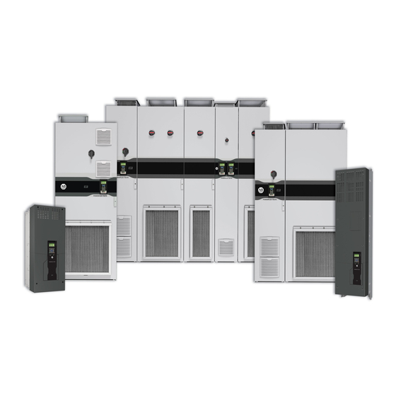
PowerFlex 755T Drives Configured to Order Program
Catalog Numbers 24G, 24J
ATTENTION: Read this document and the documents listed in the Additional Resources section about installation, configuration and operation of this equipment before you install, configure, operate or
maintain this product. Users are required to familiarize themselves with installation and wiring instructions in addition to requirements of all applicable codes, laws, and standards.
Activities including installation, adjustments, putting into service, use, assembly, disassembly, and maintenance are required to be carried out by suitably trained personnel in accordance with applicable
code of practice. If this equipment is used in a manner not specified by the manufacturer, the protection provided by the equipment may be impaired.
ATENCIÓN: Antes de instalar, configurar, poner en funcionamiento o realizar el mantenimiento de este producto, lea este documento y los documentos listados en la sección Recursos adicionales acerca de
la instalación, configuración y operación de este equipo. Los usuarios deben familiarizarse con las instrucciones de instalación y cableado y con los requisitos de todos los códigos, leyes y estándares
vigentes.
El personal debidamente capacitado debe realizar las actividades relacionadas a la instalación, ajustes, puesta en servicio, uso, ensamblaje, desensamblaje y mantenimiento de conformidad con el código
de práctica aplicable. Si este equipo se usa de una manera no especificada por el fabricante, la protección provista por el equipo puede resultar afectada.
ATENÇÃO: Leia este e os demais documentos sobre instalação, configuração e operação do equipamento que estão na seção Recursos adicionais antes de instalar, configurar, operar ou manter este
produto. Os usuários devem se familiarizar com as instruções de instalação e fiação além das especificações para todos os códigos, leis e normas aplicáveis.
É necessário que as atividades, incluindo instalação, ajustes, colocação em serviço, utilização, montagem, desmontagem e manutenção sejam realizadas por pessoal qualificado e especializado, de acordo
com o código de prática aplicável.
Caso este equipamento seja utilizado de maneira não estabelecida pelo fabricante, a proteção fornecida pelo equipamento pode ficar prejudicada.
ВНИМАНИЕ: Перед тем как устанавливать, настраивать, эксплуатировать или обслуживать данное оборудование, прочитайте этот документ и документы,
перечисленные в разделе «Дополнительные ресурсы». В этих документах изложены сведения об установке, настройке и эксплуатации данного оборудования.
Пользователи обязаны ознакомиться с инструкциями по установке и прокладке соединений, а также с требованиями всех применимых норм, законов и
стандартов.
Все действия, включая установку, наладку, ввод в эксплуатацию, использование, сборку, разборку и техническое обслуживание, должны выполняться обученным
персоналом в соответствии с применимыми нормами и правилами.
Если оборудование используется не предусмотренным производителем образом, защита оборудования может быть нарушена.
:
ACHTUNG: Lesen Sie dieses Dokument und die im Abschnitt „Weitere Informationen"aufgeführten Dokumente, die Informationen zu Installation, Konfiguration und Bedienung dieses Produkts enthalten,
bevor Sie dieses Produkt installieren, konfigurieren, bedienen oder warten. Anwender müssen sich neben den Bestimmungen aller anwendbaren Vorschriften, Gesetze und Normen zusätzlich mit den
Installations- und Verdrahtungsanweisungen vertraut machen.
Arbeiten im Rahmen der Installation, Anpassung, Inbetriebnahme, Verwendung, Montage, Demontage oder Instandhaltung dürfen nur durch ausreichend geschulte Mitarbeiter und in Übereinstimmung mit
den anwendbaren Ausführungsvorschriften vorgenommen werden.
Wenn das Gerät in einer Weise verwendet wird, die vom Hersteller nicht vorgesehen ist, kann die Schutzfunktion beeinträchtigt sein.
ATTENTION : Lisez ce document et les documents listés dans la section Ressources complémentaires relatifs à l'installation, la configuration et le fonctionnement de cet équipement avant d'installer,
configurer, utiliser ou entretenir ce produit. Les utilisateurs doivent se familiariser avec les instructions d'installation et de câblage en plus des exigences relatives aux codes, lois et normes en vigueur.
Les activités relatives à l'installation, le réglage, la mise en service, l'utilisation, l'assemblage, le démontage et l'entretien doivent être réalisées par des personnes formées selon le code de pratique en
vigueur.
Si cet équipement est utilisé d'une façon qui n'a pas été définie par le fabricant, la protection fournie par l'équipement peut être compromise.
:
,
,
,
,
ATTENZIONE Prima di installare, configurare ed utilizzare il prodotto, o effettuare interventi di manutenzione su di esso, leggere il presente documento ed i documenti elencati nella sezione "Altre risorse",
riguardanti l'installazione, la configurazione ed il funzionamento dell'apparecchiatura. Gli utenti devono leggere e comprendere le istruzioni di installazione e cablaggio, oltre ai requisiti previsti dalle leggi,
codici e standard applicabili.
Le attività come installazione, regolazioni, utilizzo, assemblaggio, disassemblaggio e manutenzione devono essere svolte da personale adeguatamente addestrato, nel rispetto delle procedure previste.
Qualora l'apparecchio venga utilizzato con modalità diverse da quanto previsto dal produttore, la sua funzione di protezione potrebbe venire compromessa.
DİKKAT: Bu ürünün kurulumu, yapılandırılması, işletilmesi veya bakımı öncesinde bu dokümanı ve bu ekipmanın kurulumu, yapılandırılması ve işletimi ile ilgili İlave Kaynaklar bölümünde yer listelenmiş
dokümanları okuyun. Kullanıcılar yürürlükteki tüm yönetmelikler, yasalar ve standartların gereksinimlerine ek olarak kurulum ve kablolama talimatlarını da öğrenmek zorundadır.
Kurulum, ayarlama, hizmete alma, kullanma, parçaları birleştirme, parçaları sökme ve bakım gibi aktiviteler sadece uygun eğitimleri almış kişiler tarafından yürürlükteki uygulama yönetmeliklerine uygun
şekilde yapılabilir.
Bu ekipman üretici tarafından belirlenmiş amacın dışında kullanılırsa, ekipman tarafından sağlanan koruma bozulabilir.
POZOR: Než začnete instalovat, konfigurovat či provozovat tento výrobek nebo provádět jeho údržbu, přečtěte si tento dokument a dokumenty uvedené v části Dodatečné zdroje ohledně instalace,
konfigurace a provozu tohoto zařízení. Uživatelé se musejí vedle požadavků všech relevantních vyhlášek, zákonů a norem nutně seznámit také s pokyny pro instalaci a elektrické zapojení.
Činnosti zahrnující instalaci, nastavení, uvedení do provozu, užívání, montáž, demontáž a údržbu musí vykonávat vhodně proškolený personál v souladu s příslušnými prováděcími předpisy.
Pokud se toto zařízení používá způsobem neodpovídajícím specifikaci výrobce, může být narušena ochrana, kterou toto zařízení poskytuje.
UWAGA: Przed instalacją, konfiguracją, użytkowaniem lub konserwacją tego produktu należy przeczytać niniejszy dokument oraz wszystkie dokumenty wymienione w sekcji Dodatkowe źródła omawiające
instalację, konfigurację i procedury użytkowania tego urządzenia. Użytkownicy mają obowiązek zapoznać się z instrukcjami dotyczącymi instalacji oraz oprzewodowania, jak również z obowiązującymi
kodeksami, prawem i normami.
Działania obejmujące instalację, regulację, przekazanie do użytkowania, użytkowanie, montaż, demontaż oraz konserwację muszą być wykonywane przez odpowiednio przeszkolony personel zgodnie z
obowiązującym kodeksem postępowania.
Jeśli urządzenie jest użytkowane w sposób inny niż określony przez producenta, zabezpieczenie zapewniane przez urządzenie może zostać ograniczone.
OBS! Läs detta dokument samt dokumentet, som står listat i avsnittet Övriga resurser, om installation, konfigurering och drift av denna utrustning innan du installerar, konfigurerar eller börjar använda eller
utföra underhållsarbete på produkten. Användare måste bekanta sig med instruktioner för installation och kabeldragning, förutom krav enligt gällande koder, lagar och standarder.
Åtgärder som installation, justering, service, användning, montering, demontering och underhållsarbete måste utföras av personal med lämplig utbildning enligt lämpligt bruk.
Om denna utrustning används på ett sätt som inte anges av tillverkaren kan det hända att utrustningens skyddsanordningar försätts ur funktion.
LET OP: Lees dit document en de documenten die genoemd worden in de paragraaf Aanvullende informatie over de installatie, configuratie en bediening van deze apparatuur voordat u dit product
installeert, configureert, bediend of onderhoudt. Gebruikers moeten zich vertrouwd maken met de installatie en de bedradingsinstructies, naast de vereisten van alle toepasselijke regels, wetten en normen.
Activiteiten zoals het installeren, afstellen, in gebruik stellen, gebruiken, monteren, demonteren en het uitvoeren van onderhoud mogen uitsluitend worden uitgevoerd door hiervoor opgeleid personeel en in
overeenstemming met de geldende praktijkregels.
Indien de apparatuur wordt gebruikt op een wijze die niet is gespecificeerd door de fabrikant, dan bestaat het gevaar dat de beveiliging van de apparatuur niet goed werkt.
,
,
,
,
,
.
.
.
.
,
Advertisement
Chapters
Table of Contents

Related Manuals for Allen-Bradley PowerFlex 755T


Summary of Contents for Allen-Bradley PowerFlex 755T
- Page 1 Product Information Original Instructions PowerFlex 755T Drives Configured to Order Program Catalog Numbers 24G, 24J ATTENTION: Read this document and the documents listed in the Additional Resources section about installation, configuration and operation of this equipment before you install, configure, operate or maintain this product.
- Page 2 PowerFlex 755T Drives Configured to Order Program Product Information Notes: Rockwell Automation Publication 750-PC108A-EN-P - April 2021...
-
Page 3: Table Of Contents
Table of Contents Introduction............. . . 5 Environmental Specifications . - Page 4 PowerFlex 755T Drives Configured to Order Program Product Information Notes: Rockwell Automation Publication 750-PC108A-EN-P - April 2021...
-
Page 5: Introduction
The PowerFlex 755T Drives Configured to Order Program combines standard PowerFlex 750-Series Drives with configured input bay and configured output bay options. This document provides product information about the configured input bays and configured output bays of the PowerFlex 755T Drives Configured to Order Program. For similar product information about the standard drive bays (or non-configured bays) of the PowerFlex 755T Drives Configured to Order Program, see the PowerFlex 750-Series Products with TotalFORCE Control Product Information, publication 750-PC100, which is shipped with the drive. -
Page 6: Catalog Number Explanation
Your product has a catalog number that contains codes that identify characteristics of the product. The catalog number is on the product data nameplates. There is a data nameplate on the outside of the door of each configured input bay, and another data nameplate on the top protective touch guard of each configured input bay or control panel. For an explanation of your catalog number, see the PowerFlex 755T Drives Configured to Order Program Installation Instructions, publication 750-IN118. - Page 7 PowerFlex 755T Drives Configured to Order Program Product Information Frame 9 Figure 5 - Frame 9 Configured Input Bay Figure 6 - Frame 9 Configured Input Bay with Figure 7 - Frame 9 Configured Input Bays with an Exhaust Hood...
-
Page 8: Overhead Clearance
Regularly inspect and replace the filter media at air-intake and exhaust locations to maintain proper airflow and cooling. For filter maintenance schedules, see the following publications: • For configured bay filters, see the PowerFlex 755T Drives Configured to Order Program Installation Instructions, publication 750-IN118. - Page 9 PowerFlex 755T Drives Configured to Order Program Product Information Figure 13 - Air-intake and Exhaust Locations: Examples Showing Frame 9 Lineups Including Configured Input Bay, Drive Bays, and Configured Output Bays Configured input bay with input fuses, top entry Configured output bays, top exit...
-
Page 10: Service Cart Access Requirements
PowerFlex 755T Drives Configured to Order Program Product Information Service Cart Access Requirements For the PowerFlex 750-Series service cart (catalog number 20-750-MCART1) to be able to access the power bay of a drive, the following requirements must be met: • Floor mounting hardware height — The maximum height of the floor mounting hardware is 254 mm (10 in.). This measurement is also an installation limit per NEC requirements for the circuit breaker/disconnect handle. -
Page 11: Recommended Mounting Hardware
PowerFlex 755T Drives Configured to Order Program Product Information Recommended Mounting Hardware See the PowerFlex 755T Drives Configured to Order Program Installation Instructions, publication 750-IN118. That publication provides information on mounting the bays with either a Rittal corner base/plinth system or a structural steel system. -
Page 12: Leakage Current
Duty Rating Each PowerFlex 755T Drives Configured to Order Program product is designed and sized based on a duty rating that is selected by the customer, based on the application. The duty rating of the drive must be set as specified on the schematics and data nameplate. - Page 13 PowerFlex 755T Drives Configured to Order Program Product Information Input Power Fuses In a configured input bay with AC line input protection using fuses, three input power fuses are used, one for each phase. For fuse specifications, see the following tables. For input power fuse locations, see...
- Page 14 PowerFlex 755T Drives Configured to Order Program Product Information Table 3 - Frame 9 Configured Input Bay AC Line Input Protection Fuses Drive Fuses Drive Fuses Cooper Cooper Continuous Continuous Input Applied Input Bussmann Input Applied Input Bussmann Output Duty...
-
Page 15: Input Power Circuit Breakers
PowerFlex 755T Drives Configured to Order Program Product Information Input Power Circuit Breakers In a configured input bay with circuit breaker AC line input protection, a 3-pole, inverse time circuit breaker is used as the protection device. For specifications, see the following tables. For input power circuit breaker... - Page 16 PowerFlex 755T Drives Configured to Order Program Product Information Table 5 - Frame 9 Configured Input Bay AC Line Input Protection Circuit Breakers Drive Circuit Breaker Drive Circuit Breaker Input Applied Continuous Input Rockwell Automation Interrupting Input Applied Continuous Input...
-
Page 17: Grounding Requirements
Recommended Grounding Scheme A single point (PE only) grounding scheme should be used. The jumpers (PE-A and PE-B) in PowerFlex 755T Configured Drive are set to be a solidly grounded system. Some applications may require alternate grounding schemes. For information on alternate grounding schemes, see Wiring and Grounding Guidelines for Pulse Width Modulated (PWM) AC Drives, publication DRIVES-IN001. The drawing package that came with your order contains a schematic that provides grounding information. -
Page 18: Frame 8 Electrical Connections
PowerFlex 755T Drives Configured to Order Program Product Information Frame 8 Electrical Connections Table 7 - Frame 8 Configured Bays - Bay to Bay, Bay to Customer Power Source, and Bay to Customer Motor Electrical Connections Made During Installation Connection Location... - Page 19 PowerFlex 755T Drives Configured to Order Program Product Information Table 8 - Frame 9 Configured Bays - Bay to Bay, Bay to Customer Power Source, and Bay to Customer Motor Electrical Connections Made During Installation All connections in frame 9 Configured input bay, control-only on page 18 •...
-
Page 20: Component And Connection Locations
PowerFlex 755T Drives Configured to Order Program Product Information Component and Connection Locations This section provides drawings of each of the configured bays. The drawings identify components and locations of electrical or control connections to customer power, other bays, or customer motor. Connections that must be made during installation have a statement in their description that they must be made during installation. -
Page 21: Frame 8 Component And Connection Locations
PowerFlex 755T Drives Configured to Order Program Product Information Frame 8 Component and Connection Locations Figure 17 - Frame 8 All Possible Configured Input Bay Upper Door External Components Item Description Infrared (IR) window - allows you to measure the temperature of the customer power input connection... -
Page 22: Frame 8 Configured Input Bay Control-Only: Internal Components
PowerFlex 755T Drives Configured to Order Program Product Information Figure 18 - Frame 8 Configured Input Bay Control-only: Internal Components Item Description Control relays Terminal blocks Fuse blocks Control power supply (24V DC) Uninterruptible power supply, and battery (behind control power supply) -
Page 23: Frame 8 Configured Input Bay With Fuses, Top Entry: Internal Components And Installation Connection Locations
PowerFlex 755T Drives Configured to Order Program Product Information Figure 19 - Frame 8 Configured Input Bay with Fuses, Top Entry: Internal Components and Installation Connection Locations Item Description Exhaust hood with internal air filter PE ground bar with ground clamps included. Terminating point to chassis ground for incoming AC line and shield. -
Page 24: Frame 8 Configured Input Bay With Fuses, Bottom Entry: Internal Components And Installation Connection Locations
PowerFlex 755T Drives Configured to Order Program Product Information Figure 20 - Frame 8 Configured Input Bay with Fuses, Bottom Entry: Internal Components and Installation Connection Locations Item Description Exhaust hood with internal air filter Control transformer Terminal lugs to supply power to the drive input bay... -
Page 25: Frame 8 Configured Input Bay With Circuit Breaker, Top Entry: Internal Components And Installation Connection Locations
PowerFlex 755T Drives Configured to Order Program Product Information Figure 21 - Frame 8 Configured Input Bay with Circuit Breaker, Top Entry: Internal Components and Installation Connection Locations Item Description Exhaust hood with internal air filter PE ground bar with ground clamps included. Terminating point to chassis ground for incoming AC line and shield. -
Page 26: Frame 8 Configured Input Bay With Circuit Breaker, Bottom Entry: Internal Components And Installation Connection Locations
PowerFlex 755T Drives Configured to Order Program Product Information Figure 22 - Frame 8 Configured Input Bay with Circuit Breaker, Bottom Entry: Internal Components and Installation Connection Locations Item Description Exhaust hood with internal air filter Control transformer Fuse block... -
Page 27: Locations
PowerFlex 755T Drives Configured to Order Program Product Information Figure 23 - Frame 8 Configured Output Bay with Output Contactor Only, Top or Bottom Exit: Internal Components and Installation Connection Item Description Locations Configured bay control connectors for control connection to configured input bay (not visible in this view, located behind bay frame). - Page 28 PowerFlex 755T Drives Configured to Order Program Product Information Figure 24 - Frame 8 Configured Output Bay with Sine-wave Filter and Output Contactor, Top or Bottom Exit: Internal Components and Installation Connection Locations Item Description Sine-wave filter capacitor bank Configured bay control connectors for control connection to configured input bay (not visible in this view, located behind bay frame).
-
Page 29: Frame 9 Component And Connection Locations
PowerFlex 755T Drives Configured to Order Program Product Information Frame 9 Component and Connection Locations Figure 26 - Frame 9 All Possible Configured Input Bay Upper Door External Components Item Description AC line input protection circuit breaker - turns power to the drive ON/OFF at the circuit... - Page 30 PowerFlex 755T Drives Configured to Order Program Product Information Figure 27 - Frame 8 and 9 Configured Input Bay with Input Protection Basic Door Internal Components Item Description Wire terminals for pilot lights and controls. These terminals are present only on configured input bays.
- Page 31 PowerFlex 755T Drives Configured to Order Program Product Information Figure 28 - Frame 9 Configured Input Bay Control-only: Internal Components and Installation Connection Locations Item Description Configured bay control connectors for control connections to configured output bay (not visible in this view, located behind bay frame).
- Page 32 PowerFlex 755T Drives Configured to Order Program Product Information Figure 29 - Frame 9 Configured Input Bay with Fuses, Top Entry: Internal Components and Installation Connection Locations Item Description Exhaust hood with internal air filter PE ground bar with ground clamps included.
- Page 33 PowerFlex 755T Drives Configured to Order Program Product Information Figure 30 - Frame 9 Configured Input Bay with Fuses, Bottom Entry: Internal Components and Installation Connection Locations Item Description Exhaust hood with internal air filter Battery Uninterruptible power supply (behind control power supply)
- Page 34 PowerFlex 755T Drives Configured to Order Program Product Information Figure 31 - Frame 9 Configured Input Bay with Circuit Breaker, Top Entry: Internal Components and Installation Connection Locations Item Description Exhaust hood with internal air filter PE ground bar with ground clamps included. Terminating point to chassis ground for incoming AC line and shield.
- Page 35 PowerFlex 755T Drives Configured to Order Program Product Information Figure 32 - Frame 9 Configured Input Bay with Circuit Breaker, Bottom Entry: Internal Components and Installation Connection Locations Item Description Exhaust hood with internal air filter Thermostat Control relay Control terminal blocks...
- Page 36 PowerFlex 755T Drives Configured to Order Program Product Information Figure 33 - Frame 9 Configured Output Bay, Top Exit: Internal Components and Installation Connection Locations Item Description Configured bay control connectors for control connections to configured input bay (not visible in this view, located behind bay frame). Connections must be made during installation.
- Page 37 PowerFlex 755T Drives Configured to Order Program Product Information Figure 34 - Frame 9 Configured Output Bay, Bottom Exit: Internal Components and Installation Connection Locations Wire Exit Bay Door Interior Item Description Configured bay control connectors for control connections to configured input bay (not visible in this view, located behind bay frame). Connections must be made during installation.
-
Page 38: Bay To Bay Connection Hardware
Bay to Bay Connection Hardware This section covers the types of hardware that are used to electrically connect bays when they are shipped as part of separate shipping sections. To make these connections, follow the instructions in the PowerFlex 755T Drives Configured to Order Program Installation Instructions, publication 750-IN118. -
Page 39: Braided Busbar To Drive Output Busbar Connection Hardware
PowerFlex 755T Drives Configured to Order Program Product Information Braided Busbar to Drive Output Busbar Connection Hardware To determine if you must make a connection using this hardware during installation, see Electrical Connections Made to Each Configured Bay During Installation on page 17. -
Page 40: Barrel Lug To Drive Input Busbar Connection Hardware
PowerFlex 755T Drives Configured to Order Program Product Information Barrel Lug to Drive Input Busbar Connection Hardware To determine if you must make a connection using this hardware during installation, see Electrical Connections Made to Each Configured Bay During Installation on page 17. -
Page 41: Configured Bay Control Connection Hardware
PowerFlex 755T Drives Configured to Order Program Product Information Configured Bay Control Connection Hardware Configured bay control connectors are used for control connections between a configured input bay and configured output bay, so they are only present in bay lineups that contain both a configured input bay and a configured output bay. - Page 42 PowerFlex 755T Drives Configured to Order Program Product Information Figure 44 - Configured Bay Control Connections on the Frame 9 Configured Input Bay Item Identification Description PLUG2 Four-pole female connector 120V AC PLUG2 Four-pole male connector 120V AC. Must connect to item 1 during installation.
- Page 43 PowerFlex 755T Drives Configured to Order Program Product Information Figure 45 - Configured Bay Control Connections on the Frame 9 Configured Output Bay Item Identification Description PLUG3 Four-pole female connector 24V DC PLUG3 Four-pole male connector 24V DC. Must connect to item 1 during installation.
-
Page 44: Customer Connections For Ac Line Input Power And Motor Power
This section describes the cabling recommendations for three-phase power and motor connections for the configured input and output bays. For detailed installation instructions, including cable entry and exit and customer connection options, see the PowerFlex 755T Drives Configured to Order Program Installation Instructions, publication 750-IN118. Also see the Wiring and Grounding Guidelines for Pulse Width Modulated (PWM) AC Drives, publication DRIVES-IN001, for more information on grounding. -
Page 45: Connection Hardware For Customer Power Source And Motor
PowerFlex 755T Drives Configured to Order Program Product Information Connection Hardware for Customer Power Source and Motor This section includes: UL Listed Barrel Lugs, Barrel Lug to L-Bracket to Busbar Connections, Barrel Lug to L-Bracket to Busbar Connections on page... -
Page 46: Move The Bays
Join the Bays If your product was shipped divided into multiple shipping sections, you must join the sections together at the installation site. For instructions on joining bays see the PowerFlex 755T Drives Configured to Order Program Installation Instructions, publication 750-IN118. -
Page 47: Additional Resources
PowerFlex 755T Drives Configured to Order Program Product Information Additional Resources These documents and resources contain additional information that is related to the PowerFlex 755T Drives Configured to Order Program. Shipped with the Product A documentation package is shipped with your product. It contains the following:... - Page 48 Rockwell Otomasyon Ticaret A.Ş. Kar Plaza İş Merkezi E Blok Kat:6 34752, İçerenköy, İstanbul, Tel: +90 (216) 5698400 EEE Yönetmeliğine Uygundur *PN-606121* Allen-Bradley, expanding human possibility, PowerFlex, Rockwell Automation, and TotalFORCE are trademarks of Rockwell Automation, Inc. Trademarks not belonging to Rockwell Automation are property of their respective companies.
Need help?
Do you have a question about the PowerFlex 755T and is the answer not in the manual?
Questions and answers