
Related Manuals for Dell EMC OptiPlex 7090 Ultra


Summary of Contents for Dell EMC OptiPlex 7090 Ultra
- Page 1 OptiPlex 7090 Ultra Setup and specifications guide Regulatory Model: D13U Regulatory Type: D13U002 January 2021 Rev. A00...
- Page 2 Notes, cautions, and warnings NOTE: A NOTE indicates important information that helps you make better use of your product. CAUTION: A CAUTION indicates either potential damage to hardware or loss of data and tells you how to avoid the problem. WARNING: A WARNING indicates a potential for property damage, personal injury, or death.
- Page 3 Contents Chapter 1: Set up your OptiPlex 7090 Ultra................... 5 Installing the device on a fixed stand..........................5 Monitor tilt angle................................14 Installing the device on a Pro 1 height-adjustable stand..................14 Stand tilt, pivot, and swivel images.........................23 Installing device on offset VESA mount........................23 Installing the device on a Pro 2 height-adjustable stand..................30...
- Page 4 Chapter 5: Getting help.......................90 Contacting Dell.................................. 90 Contents...
- Page 5 Set up your OptiPlex 7090 Ultra Topics: • Installing the device on a fixed stand • Installing the device on a Pro 1 height-adjustable stand • Installing device on offset VESA mount • Installing the device on a Pro 2 height-adjustable stand •...
- Page 6 6. Remove the screw that secures the stand mounting bracket to the stand. 7. Lift the mounting bracket to release the hooks on the bracket from the slots on the stand. Set up your OptiPlex 7090 Ultra...
- Page 7 8. To avoid any damage to the monitor, ensure that you place the monitor on a protective sheet. 9. Align the screws on the mounting bracket with the screw holes on the monitor. 10. Tighten the four captive screws to secure the mounting bracket to the monitor. Set up your OptiPlex 7090 Ultra...
- Page 8 11. Select the height at which you want to mount the monitor and align the hooks on the mounting bracket with the slots on the stand. 12. Replace the screw to secure the fixed stand to the monitor. Set up your OptiPlex 7090 Ultra...
- Page 9 15. Connect the power, network, keyboard, mouse, and display cables to the device and to the power outlet. NOTE: To avoid any pinching or crimping of the cables while closing the stand cover, it is recommended that you route the cables as indicated in the image. Set up your OptiPlex 7090 Ultra...
- Page 10 All the cables and ports are used depending on the peripherals chosen and the configuration of the computer. 16. Slide the back cover, along with the device, into the stand until you hear a click. Set up your OptiPlex 7090 Ultra...
- Page 11 17. Lock the device and the stand cover. Set up your OptiPlex 7090 Ultra...
- Page 12 18. Press the power button to turn on the device. Set up your OptiPlex 7090 Ultra...
- Page 13 Set up your OptiPlex 7090 Ultra...
- Page 14 1. Align and insert the slots on the height-adjustable stand into the tab on the stand base. 2. Lift and tilt the stand base. 3. Tighten the captive screw to secure the stand to the base. Set up your OptiPlex 7090 Ultra...
- Page 15 4. To avoid any damage to the monitor, ensure that you place the monitor on a protective sheet. 5. For installing the height-adjustable stand to the monitor: a. Align and insert the hooks on the mounting bracket on the stand into the slots on the monitor, until you hear a click. Set up your OptiPlex 7090 Ultra...
- Page 16 Align and insert the QR tabs on the stand into the slots on the QR to VESA bracket on the monitor. d. Tighten the thumb screw to secure the stand to the QR to VESA bracket. Set up your OptiPlex 7090 Ultra...
- Page 17 8. Slide and lift the cover to release it from the stand. 9. Align the vents on the device with the vents on the stand cover. 10. Lower the device in the stand until you hear a click. Set up your OptiPlex 7090 Ultra...
- Page 18 To avoid any pinching or crimping of the cables while closing the stand cover, it is recommended that you route the cables as indicated in the image. NOTE: All the cables and ports are used depending on the peripherals chosen and the configuration of the computer. Set up your OptiPlex 7090 Ultra...
- Page 19 12. Slide the back cover, along with the device, into the stand until you hear a click. Set up your OptiPlex 7090 Ultra...
- Page 20 13. Lock the device and the stand cover. Set up your OptiPlex 7090 Ultra...
- Page 21 14. Press the power button to turn on the device. Set up your OptiPlex 7090 Ultra...
- Page 22 Set up your OptiPlex 7090 Ultra...
- Page 23 Installing device on offset VESA mount 1. Align the screw holes on the device with the screw holes on the offset VESA mount. 2. Install the four screws to secure the device to the offset VESA mount. Set up your OptiPlex 7090 Ultra...
- Page 24 4. Align the screw holes on the offset VESA mount with the screw holes on the monitor. 5. Install the four screw spacers and the screws to secure the offset VESA mount to the monitor. Set up your OptiPlex 7090 Ultra...
- Page 25 6. Insert the hooks on the mounting bracket of the monitor arm stand into the slots on the offset VESA mount on the monitor. 7. Lower the monitor on the monitor arm stand until you hear a click. Set up your OptiPlex 7090 Ultra...
- Page 26 8. To install the offset VESA mount on a Dell E-Series monitor: a. Align and install the four screws to secure the device to the offset VESA mount. Set up your OptiPlex 7090 Ultra...
- Page 27 Remove the VESA cover from the back of the monitor and secure the offset VESA mount along with the device to the monitor. Set up your OptiPlex 7090 Ultra...
- Page 28 Set up your OptiPlex 7090 Ultra...
- Page 29 Set up your OptiPlex 7090 Ultra...
- Page 30 1. Align and insert the slots on the height-adjustable stand into the tab on the stand base. 2. Lift and tilt the stand base. 3. Tighten the captive screw to secure the stand to the base. Set up your OptiPlex 7090 Ultra...
- Page 31 NOTE: For the large height adjustable stand, replacing the screw to the unlock icon screw hole in the stand base ensures the rotation of the 30-inch - 32-inch monitor. Set up your OptiPlex 7090 Ultra...
- Page 32 4. To avoid any damage to the monitor, ensure that you place the monitor on a protective sheet. 5. For installing the height-adjustable stand to the monitor: a. Align and insert the hooks on the mounting bracket on the stand into the slots on the monitor, until you hear a click. Set up your OptiPlex 7090 Ultra...
- Page 33 Set up your OptiPlex 7090 Ultra...
- Page 34 Align and insert the QR tabs on the stand into the slots on the QR to VESA bracket on the monitor. d. Tighten the thumb screw to secure the stand to the QR to VESA bracket. Set up your OptiPlex 7090 Ultra...
- Page 35 Set up your OptiPlex 7090 Ultra...
- Page 36 7. To release the stand cover, press the button on the side of the stand chassis. 8. Slide and lift the cover to release it from the stand. Set up your OptiPlex 7090 Ultra...
- Page 37 9. Slide and release the inner bar on the lower edge of the stand cover. Set up your OptiPlex 7090 Ultra...
- Page 38 10. Align the vents on the device with the vents on the stand cover and slide the device in the cover. Set up your OptiPlex 7090 Ultra...
- Page 39 11. Slide the inner bar back to the lower edge of the stand cover to lock the device to the cover. Set up your OptiPlex 7090 Ultra...
- Page 40 12. Connect the power, network, keyboard, mouse, and display cables to the device and to the power outlet. Set up your OptiPlex 7090 Ultra...
- Page 41 13. To avoid any pinching or crimping of the cables while closing the stand cover, it is recommended that you route the cables as indicated in the image. NOTE: All the cables and ports are used depending on the peripherals chosen and the configuration of the computer. Standard Height Adjustable Stand Set up your OptiPlex 7090 Ultra...
- Page 42 Large Height Adjustable Stand Set up your OptiPlex 7090 Ultra...
- Page 43 14. Slide the stand cover, along with the device, into the stand until you hear a click. Set up your OptiPlex 7090 Ultra...
- Page 44 15. Lock the device and the stand cover. Set up your OptiPlex 7090 Ultra...
- Page 45 16. Press the power button to turn on the device. Set up your OptiPlex 7090 Ultra...
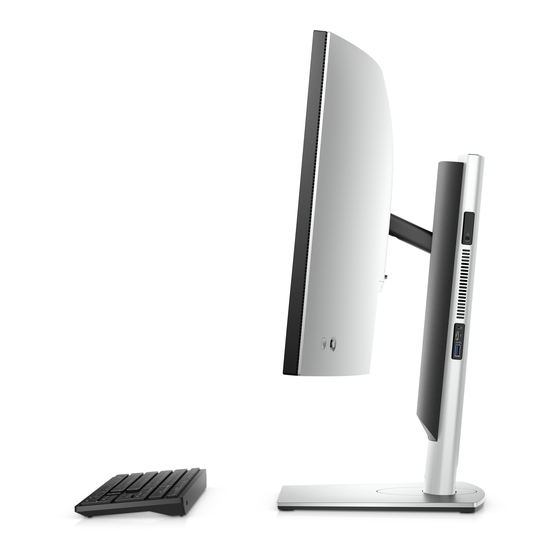
- Page 46 Stand tilt, pivot, and swivel images For 19-inch to 27-inch monitor (Standard height adjustable stand): Set up your OptiPlex 7090 Ultra...
- Page 47 For 30-inch to 32-inch monitor (Large height adjustable stand): Set up your OptiPlex 7090 Ultra...
- Page 48 For monitors > 32-inch (Large height adjustable stand): Set up your OptiPlex 7090 Ultra...
- Page 49 1. Full Function a. Press the release button to open the cable cover. b. Align the screw holes on the wall mount in the wall and mark them against the wall using a pencil. Set up your OptiPlex 7090 Ultra...
- Page 50 Drill the screw marks on the wall and insert the three screw anchors into the screw holes in the wall. Set up your OptiPlex 7090 Ultra...
- Page 51 Align the screw holes on the wall mount with the screw holes on the wall and install the three screws to secure the wall mount in the wall. Set up your OptiPlex 7090 Ultra...
- Page 52 Align the screw holes on the device with the screw holes on the wall mount bracket. f. Install the four screws to secure the device to the wall mount bracket. Set up your OptiPlex 7090 Ultra...
- Page 53 Insert the hooks on the mounting bracket of the wall mount into the slots on the wall mount bracket module. h. Align and insert the hooks on the wall mount bracket module into the slots on the wall mount until it clicks into place Set up your OptiPlex 7090 Ultra...
- Page 54 Connect the power, network, keyboard, mouse, and display cables to the device and to the power outlet. Set up your OptiPlex 7090 Ultra...
- Page 55 To avoid any pinching or crimping of the cables while closing the stand cover, it is recommended that you route the cables as indicated in the image. NOTE: All the cables and ports are used depending on the peripherals chosen and the configuration of the computer. Set up your OptiPlex 7090 Ultra...
- Page 56 Close the stand cover. Set up your OptiPlex 7090 Ultra...
- Page 57 Lock the device and the stand cover. Set up your OptiPlex 7090 Ultra...
- Page 58 2. Simple Function a. Align the screw holes on the wall mount in the wall and mark them using a pencil. Set up your OptiPlex 7090 Ultra...
- Page 59 Drill the screw marks on the wall and insert the two screws into the screw holes in the wall. Set up your OptiPlex 7090 Ultra...
- Page 60 Align the screw holes on the device with the screw holes on the wall mount bracket. d. Install the four screws to secure the device to the wall mount bracket. Set up your OptiPlex 7090 Ultra...
- Page 61 Connect the power, network, keyboard, mouse, and display cables to the device and to the power outlet. Set up your OptiPlex 7090 Ultra...
- Page 62 Align the screws on the wall with the retention clips on the wall mount bracket module. g. Mount the wall mount bracket module in the screws on the wall. Set up your OptiPlex 7090 Ultra...
- Page 63 Press the power button to turn on the device. Set up your OptiPlex 7090 Ultra...
- Page 64 Set up your OptiPlex 7090 Ultra...
- Page 65 Create a USB recovery drive for Windows Create a recovery drive to troubleshoot and fix problems that may occur with Windows. An empty USB flash drive with a minimum capacity of 16 GB is required to create the recovery drive. NOTE: This process may take up to an hour to complete.
- Page 66 View of OptiPlex 7090 Ultra Topics: • • Bottom • Left • Right • Front and back • Stands view • System board layout 1. Fan vent 2. Power button View of OptiPlex 7090 Ultra...
- Page 67 2. 1 USB 3.2 Gen 2 Type-A ports with SmartPower On 3. 1 USB 3.2 Gen 2 Type-A ports with SmartPower On 4. RJ45 Ethernet port 5. DC-in port 6. 1 USB 3.2 Gen 2 Type-C port with Display Port Alt Mode/Power delivery View of OptiPlex 7090 Ultra...
- Page 68 Left 1. Headset/Universal Audio Jack 2. Fan vent 3. Hard-drive status LED 4. 1 Thunderbolt 4 port with DisplayPort Alt Mode/USB4 5. 1 USB 3.2 Gen 2 Type-A port with PowerShare View of OptiPlex 7090 Ultra...
- Page 69 Right 1. Kensington lock slot 2. Security screw lock slot 3. Air vents Front and back Front View of OptiPlex 7090 Ultra...
- Page 70 Back View of OptiPlex 7090 Ultra...
- Page 71 1. Hard drive cover/ M.2 Solid-state drive cover Stands view Fixed stand: View of OptiPlex 7090 Ultra...
- Page 72 Pro 1.0 Height-adjustable stand: Pro 2.0 Height Adjustable Stand Standard: View of OptiPlex 7090 Ultra...
- Page 73 Pro 2.0 Height Adjustable Stand Large: View of OptiPlex 7090 Ultra...
- Page 74 Offset VESA Mount: View of OptiPlex 7090 Ultra...
- Page 75 VESA Adapter for Pro2.0 Height Adjustable Stand: View of OptiPlex 7090 Ultra...
- Page 76 VESA Adapter for Pro1.0 Height Adjustable Stand: View of OptiPlex 7090 Ultra...
- Page 77 Wall Mount: View of OptiPlex 7090 Ultra...
- Page 78 View of OptiPlex 7090 Ultra...
- Page 79 System board layout 1. System fan connector 2. Power button connector 3. Coin-cell battery connector 4. Hard-drive connector 5. Daughter board connector 6. CPU 7. M.2 SSD PCIe Gen4 connector 8. M.2 WLAN connector 9. Memory-module slots View of OptiPlex 7090 Ultra...
- Page 80 Specifications of OptiPlex 7090 Ultra Topics: • Dimensions and weight • Processor • Chipset • Operating system • Commercial platform Windows 10 N-2 and 5yrs OS supportability • Memory • Intel Optane Memory H10 with Solid State Storage • External ports •...
- Page 81 Semi-Annual Channel Windows 10 version (N) and qualify (but not ship) the previous two versions (N-1, N-2). This device platform, OptiPlex 7090 Ultra will RTS with Windows 10 version (20H2, 20H1, 19H2) at the time of launch, and this version will determine the N-2 versions that are initially qualified for this platform.
- Page 82 PCIe 3 x4 NVMe Interface ● One PCIe 3 x2 for Optane memory ● One PCIe 3 x2 for solid-state storage Connector Form factor 2280 Capacity (Intel Optane memory) 32 GB Capacity (solid-state storage) 512 GB Specifications of OptiPlex 7090 Ultra...
- Page 83 Generation or higher Intel Core i3/i5/i7 processors ● Windows 10 64-bit version or higher (Anniversary Update) ● Intel Rapid Storage Technology driver version 15.9.1.1018 or higher External ports The following table lists the external ports of your OptiPlex 7090 Ultra. Table 6. External ports Description Values...
- Page 84 Values Model number Intel i219LM Transfer rate 10/100/1000 Mbps Wireless module The following table lists the Wireless Local Area Network (WLAN) modules supported on your OptiPlex 7090 Ultra. Table 9. Wireless module specifications Description Option one Option two Model number...
- Page 85 Up to 1 TB Opal 2.0 solid-state drive eMMC eMMC Upto 64 GB Power adapter The following table lists the power adapter specifications of your OptiPlex 7090 Ultra. Table 12. Power adapter specifications Description Values Type 90 W Connector dimensions: External diameter 4.50 mm...
- Page 86 (primary power source), connecting a second power source and disconnecting the primary power source will shut down the device. However, if the secondary power source is disconnected while the primary power source is connected, the system continues to operate normally. Specifications of OptiPlex 7090 Ultra...
- Page 87 Type-C display settings When using a Dell USB Type-C display to power on your OptiPlex 7090 Ultra, to avoid any power loss to the device when the display is turned off or on Standby mode, ensure that the Always on USB-C Charging setting on the display is enabled.
- Page 88 -15.2 m to 10668 m (-49.87 ft to 35000 * Measured using a random vibration spectrum that simulates user environment. † Measured using a 2 ms half-sine pulse when the hard drive is in use. Specifications of OptiPlex 7090 Ultra...
- Page 89 1. Press <F12> when the Dell logo appears to initiate a one-time boot menu. Go to BIOS Setup. 2. Select Power Management. 3. Navigate to USB Wake Support 4. Turn on Enable USB Wake Support 5. Navigate to Deep Sleep control 6. Disable Deep Sleep Specifications of OptiPlex 7090 Ultra...
- Page 90 Getting help Topics: • Contacting Dell Contacting Dell NOTE: If you do not have an active Internet connection, you can find contact information on your purchase invoice, packing slip, bill, or Dell product catalog. Dell provides several online and telephone-based support and service options. Availability varies by country and product, and some services may not be available in your area.
Need help?
Do you have a question about the OptiPlex 7090 Ultra and is the answer not in the manual?
Questions and answers