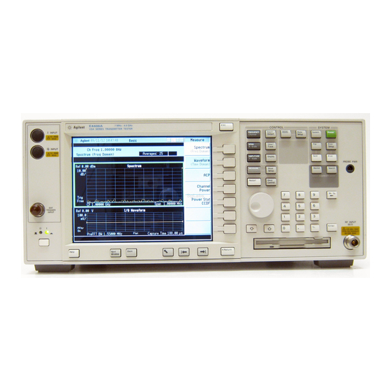
Agilent Technologies E4406A VSA Series Installation Note
Transmitter tester cpu retrofit kit for instruments with serial prefix us3948 and below and with cpu assemblies e4406-60073 or e4406-60040
Hide thumbs
Also See for E4406A VSA Series:
- Programmer's manual (420 pages) ,
- Service manual (266 pages) ,
- Measurement manual (124 pages)
Advertisement
Quick Links
Installation Note
Agilent E4406A VSA Series Transmitter Tester CPU
Retrofit Kit for Instruments with Serial Prefix
US3948 and below and with CPU Assemblies
E4406-60073 or E4406-60040
Kit Part Number E4406-60238
Part Number E4406-90278
Printed in USA April 2011
Supersedes February 2005
Advertisement

Related Manuals for Agilent Technologies E4406A VSA Series


Summary of Contents for Agilent Technologies E4406A VSA Series
- Page 1 Installation Note Agilent E4406A VSA Series Transmitter Tester CPU Retrofit Kit for Instruments with Serial Prefix US3948 and below and with CPU Assemblies E4406-60073 or E4406-60040 Kit Part Number E4406-60238 Part Number E4406-90278 Printed in USA April 2011 Supersedes February 2005...
- Page 2 The information contained in this document is subject to change without notice. Agilent Technologies makes no warranty of any kind with regard to this material, including but not limited to, the implied warranties of merchantability and fitness for a particular purpose. Agilent Technologies shall not be liable for errors contained herein or for incidental or consequential damages in connection with the furnishing, performance, or use of this material.
- Page 3 A22 CPU Retrofit Kit A22 CPU Retrofit Kit Products Affected: VSA E4406A Serial Numbers: US3948 and below To Be Performed By: (X) Agilent Service Center (X) Personnel Qualified by Agilent (X) Customer Estimated Installation Time: 2 Hours Introduction This kit provides the hardware and installation instructions necessary for installing the E4406-60060 CPU assembly into E4406As with serial prefix US3948 and below and with CPU assemblies E4406-60073 or E4406-60040.
- Page 4 A22 CPU Retrofit Kit Before You Start Before starting to disassemble the instrument: • Check that you are familiar with the safety symbols marked on the instrument, and read the general safety considerations and the safety note definitions given in the front of this guide. •...
-
Page 5: Installation Procedure
Installation Procedure Installation Procedure Step 1. Remove the Outer Case CAUTION If the instrument is placed on its face during any of the following procedures, be sure to use a soft surface or soft cloth to avoid damage to the front panel, keys, or input connector. - Page 6 Installation Procedure Step 2. Remove the Top Brace 1. Using the T-10 driver, remove the 7 top screws, one is covered with the security label (3) and the 10 side screws (2) attaching the top brace (1) to the deck. The top screws are different from the side screws.
- Page 7 Installation Procedure Step 3. Remove the A25 SCSI Board 1. At the rear of the instrument, use a T-10 driver to remove the 7 screws (1) securing the small panel to the frame. 2. The A25 board can be removed through the rear panel by pulling upon the board to disengage it from the CPU board.
- Page 8 Installation Procedure Step 4. Remove the A22 CPU Assembly 1. Locate and unseat the A10 Digital IF assembly and the A7 BaseBand IQ assembly (if present). (See Figure 5.) It is not necessary to completely remove the assemblies from the instrument or disconnect any of the cables connected to the digital IF assembly or the baseband IQ assembly.
- Page 9 Installation Procedure Step 5. Remove the A22A1 DRAM and A22A2 Flash Memory Assemblies 1. Orient the A22 Processor assembly so its rear-panel plate is facing you. Locate the A22A1 DRAM Memory and A22A2 Flash Memory assemblies. (See Figure 2. Cut the 4 plastic standoffs around the A22A1 assembly and the 4 plastic standoffs around the A22A2 assembly with diagonal pliers or a utility knife.
- Page 10 Installation Procedure Step 7. Install the replacement A22 CPU Assembly and A25 SCSI Assembly 1. Slide the CPU assembly back into the chassis and assure the CPU and motherboard connector mate. The CPU plate should fit snugly against the rear frame. 2.
- Page 11 Installation Procedure Step 8. Detach the Front Frame 1. Refer to Figure 6. Using the T-10 driver, remove the 6 screws (1) that attach the front frame assembly (2) to the deck. 2. Disengage the green external front trigger cable (4) from the clips that secure it to the inside of the front frame.
- Page 12 Installation Procedure Step 9. Install the new Front Panel Interface Board Assembly 1. Refer to Figure 7. Using the T-10 driver, remove the 11 screws (1) securing the shield (2) to the front frame. Lift the shield from the front frame. Figure 7 Front Frame Shield Removal 2.
- Page 13 Installation Procedure 4. Unplug the display flat flex cable (4) from the front panel interface board. To do this, you must first pull up on both sides of the locking mechanism of the ribbon cable connector. 5. Using the T-10 driver, remove the 7 screws (1) that secure the front panel interface board (5) to the front frame assembly.
- Page 14 Installation Procedure Step 10. Reattach the Front Frame Assembly 1. Place the front frame assembly in front of the deck. 2. Refer to Figure 6. Connect the ribbon cable (3) to the A3 front panel interface board if it became disconnected.
- Page 15 Installation Procedure Step 11. Install the Top Brace and Outer Case 1. Carefully position the top brace on the deck. Reference the two alignment pins and the two alignment holes. Make sure that no coaxial cables will get pinched underneath the brace. 2.
- Page 16 Installation Procedure Step 13. Program the instrument's serial number into the replacement CPU Whenever the main CPU is replaced it is necessary to configure the instrument’s serial number stored on the CPU assembly. You are given just once chance to correctly enter the instrument's serial number from the front panel.