
Related Manuals for Kamstrup M-Bus Master MultiPort 250D


Summary of Contents for Kamstrup M-Bus Master MultiPort 250D
- Page 1 M-Bus Master MultiPort 250D Installation and User Guide Kamstrup A/S · Industrivej 28, Stilling · DK-8660 Skanderborg · T: +45 89 93 10 00 · info@kamstrup.com · kamstrup.com...
-
Page 2: Table Of Contents
Operation of M-Bus Master MultiPort 250D 3.7.1 Current and voltage 7.1 Keys 3.8 M-Bus Repeater Input 7.2 Light emitting diodes Cabling 7.2.1 Power 4.1 Special features of M-Bus Master MultiPort 250D 7.2.2 Request 7.2.3 Data 4.2 Electrical conditions in an M-Bus network 7.2.4 Overload 4.2.1 M-Bus modules 7.3 Display... - Page 3 7.12.7 Communication Test 7.7.2 Display of logged data 7.12.8 Bus Info 7.8 Settings of MultiPort 250D 7.12.9 Restart master 7.8.1 Date and time 7.12.10 About M-Bus Master MultiPort 250D 7.8.2 Contrast Web Server 7.8.3 M-Bus GSM/GPRS 7.9 Green Mode Dimensioned drawings 7.10 Other settings...
-
Page 4: Introduction
The maximum size of an M-Bus network using Kamstrup M-Bus Master MultiPort 250D is 250 meters. If a number of masters are configured as repeaters and coupled in cascade and only secondary addressing is used, a total of 1,250 meters can be connected, and the total cable length can be up to approx. -
Page 5: Functionality
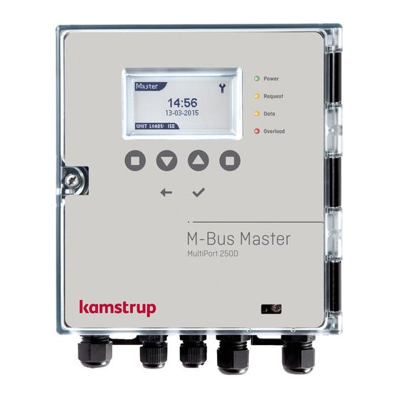
M-Bus Master MultiPort 250D 2 Functionality Kamstrup M-Bus Master MultiPort 250D is an M-Bus master designed for the connection of up to 250 meters with M-Bus interface. The cable length of a master can be up to 2800 m depending on cable type. - Page 6 Four light emitting diodes indicate the status of mains supply, data communication as well as possible overload and short-circuit of the M-Bus network. Kamstrup M-Bus Master MultiPort 250D has been designed for installation indoors. The protection class can be up to IP Kamstrup A/S • 5512853_C1_GB_01.2017...
-
Page 7: Overview Of Functions
• Usable as master, repeater and level converter • Backlit 128 x 64 pixels LCD • Reading via display of both Kamstrup meters and third-party brands • Supports primary, secondary and enhanced secondary addressing • Collision detection with break signal •... -
Page 8: Connections
All connections in MultiPort 250D are screw terminals with max. cable size of 2 mm The protection class of M-Bus Master MultiPort 250D can be up to IP 67. IP 67 means full dust protection as well as water tightness for minimum 30 minutes down to 1 metre. -
Page 9: Overview Of Connections
M-Bus Master MultiPort 250D Overview of connections Connection number on Designation Colour/connector No. Description master Power supply Blue Neutral Brown Live Yellow/green Protective earth USB 2.0 Max recommended cable length: 5 m Red/1 5 V power supply White/2 Data -... -
Page 10: Power Supply
M-Bus Master MultiPort 250D 3.2 Power supply The power supply of M-Bus Master MultiPort 250D is the switch mode type which requires voltage between 100 V and 240 V. The frequency can be 50 Hz or 60 Hz. The mains cable is connected to the master through the associated gland. The diameter must be between 4 and 8 mm. - Page 11 M-Bus Master MultiPort 250D From www.kamstrup.com, navigate to ”Service & Support”, and click on “Go to downloads”. On the new page, scroll down to the „M-bus Master“ area, clik on “Go to download”, and you will see this page: Click the „Download USB driver“ link. You will now be asked to select „Run“ or „Save“. When selecting „Run“, the installation starts automatically.
- Page 12 M-Bus Master MultiPort 250D When the setup program has been started, just follow the instructions in the wizard. Click ”Next” to continue or ”Cancel” to stop the setup. Kamstrup A/S • 5512853_C1_GB_01.2017...
- Page 13 M-Bus Master MultiPort 250D Depending on the security settings in your computer, this popup may occur. The Device Driver Installation wizard starts to run. Pressing „Finish“, the installation is completed. Kamstrup A/S • 5512853_C1_GB_01.2017...
-
Page 14: Rs-232
M-Bus Master MultiPort 250D 3.4 RS-232 M-Bus Master MultiPort 250D’s RS-232 connection can be used for M-Bus communication on an equal basis with the other serial connections. The following communication speeds can be used for M-Bus communication: • 300 baud 8E1 •... -
Page 15: Rs-485
The master’s integrated port controller makes sure that communication is only possible on one serial port at a time. 3.6 Optical eye M-Bus Master MultiPort 250D’s optical eye can be used for M-Bus communication on an equal basis with the other serial connections. -
Page 16: M-Bus Repeater Input
M-Bus Master MultiPort 250D 3.8 M-Bus Repeater Input Setting as master or repeater. Kamstrup M-Bus Master MultiPort 250D can be used as both master and repeater. Used as master, up to 250 meters can be connected in an M-Bus system. -
Page 17: Cabling
M-Bus Master MultiPort 250D The master’s display shows that it is configured as a repeater. When the master is configured as a repeater, only the menu points which can be used with this configuration are displayed. 250D configured as repeater. -
Page 18: Special Features Of M-Bus Master Multiport 250D
M-Bus Master MultiPort 250D has been designed with the newest cable driver technology, and is, therefore, rather insensitive to the capacity of the M-Bus network. Thus, designing an M-Bus network to be used together with M-Bus Master MultiPort 250D, the limiting factor as to possible cable length will primarily be the cable resistance in the network. -
Page 19: Cable
M-Bus Master MultiPort 250D 4.3.1 Cable The cable resistance and capacity must be as low as possible. The thicker the cable, the lower the resistance. The thicker the cable, the higher the capacity. An M-Bus cable must as a minimum be able to handle 50 V and 500 mA. -
Page 20: Cable Topology
M-Bus Master MultiPort 250D In big networks using secondary addressing, worst case load must be considered as 250 slaves of 1 UL (Unit Load) each drawing 5.4 A, which thin cables will not be able to withstand. Measurement of loop resistance. - Page 21 M-Bus Master MultiPort 250D M-Bus M ster M-Bus M ster Bus topology with cable looped through meters. Bus topology with each individual meter connected to the bus. M-Bus M ster Star topology connecting each individual meter directly to the M-Bus Master.
- Page 22 M-Bus Master MultiPort 250D Junction box Area 2 Area 4 4th floor 3rd floor M-Bus Master M-Bus Repeater Area 1 Area 3 2nd floor M-Bus M ster M-Bus M ster 1st floor 24-25 24-25 53-54 24-25 Example of the construction of a large M-Bus network.
-
Page 23: Examples Of Network Sizes
M-Bus Master MultiPort 250D 4.3.3 Examples of network sizes The below tables show examples of possible network sizes with different cable configurations. Each connected repeater increases the possible cable length by the below lengths. Cable type 0.34 mm (56 Ohm/110 nF) -
Page 24: M-Bus Addressing
5.2 Secondary addressing (00000001-99999999) Secondary addressing uses the last 8 digits of the meter number as M-Bus ID. Kamstrup MULTICAL® meters use the customer number as their secondary addresses, which makes it possible to change the secondary address. Enhanced secondary addressing (00000001-99999999)/(00000001-99999999) The meter’s serial number is used for enhanced secondary addressing. -
Page 25: M-Bus Communication
M-Bus communication is half duplex allowing two-way communication with one M-Bus slave at a time. The master’s integrated port controller makes sure that communication is only possible on one serial port at a time. Communication speed M-Bus Master MultiPort 250D supports the following communication speeds: • 300 baud 8E1 • 2400 baud 8E1 •... -
Page 26: Keys
M-Bus Master MultiPort 250D Keys According to the display structure, the left and right function keys are soft keys, i.e. their function depends on the displayed menu point. The six keys have the following functions: Left function key Right function key Typically page down or go left. -
Page 27: Power
Red light emitting diode which flashes when the load on the M-Bus network is between 375 and 500 mA. It is permanently lit when the load on the M-Bus network exceeds 500 mA. 375 mA corresponds to 250 UL (M-Bus Unit Loads). At 500 mA, M-Bus Master MultiPort 250D disconnects due to overload or short circuit condition. Display The resolution of the backlit display is 128x64 pixels. -
Page 28: Menu Overview
M-Bus Master MultiPort 250D Location Shows where you are in a menu list, a meter list or a meter data list. Alternatively, it displays details of an ongoing function, e.g. secondary scanning at 2400 baud. Status Indicates the status of the screen in question (refers to Title). It can, for example, indicate the number of slaves found during scanning. - Page 29 M-Bus Master MultiPort 250D 7.5.1 Primary scanning Primary scanning scans for meters with M-Bus addresses between 001 and 250. Select type of scanning. Select speed. Primary scanning. Scanning completed. When performing an additional scanning, it is possible to keep the existing scanning list and add additionally found meters to the list.
- Page 30 M-Bus Master MultiPort 250D 7.5.2 Secondary scanning Secondary scanning scans for meters with M-Bus addresses between 00000000 and 99999999. Wildcard search is indicated by one or several digits of the meter number being replaced by ”F”. Select type of scanning...
- Page 31 M-Bus Master MultiPort 250D Meter reading by means of MultiPort 250D Meter reading is effected either immediately after a scanning or from the menu Read Meter. 7.6.1 Meter reading after scanning When the scanning has been completed, select Read Meter using the right function key to have the list of meters found displayed.
- Page 32 M-Bus Master MultiPort 250D 7.6.2 Meter reading from the menu Read Meter M-Bus Master MultiPort 250D remembers the meters from the latest scanning. This means that it is not necessary to scan the whole M-Bus network every time a meter is to be read.
- Page 33 M-Bus Master MultiPort 250D Then select the amount of log entries to read. The entries can be selected from 1 to 15. The more entries you want to read, the longer time is needed to fetch the information from the energy meters.
- Page 34 M-Bus Master MultiPort 250D This screen may appear if an attempt is made to read an energy meter that does not support M-Bus logs. In this case, arrows in the bottom left and bottom right indicate that more logged items are ready to be displayed using the left (...
- Page 35 M-Bus Master MultiPort 250D 7.8.1 Date and time Adjust time and date using the keys. The value is changed using and the left and right function keys are used for switching between the individual values. The menu Settings. Adjustment of time and date.
- Page 36 M-Bus Master MultiPort 250D Legacy Delay If the master is connected to old generations of Kamstrup M-Bus modules and secondary addressing is used, Legacy Delay shall be min. 15 seconds. Legacy Delay ensures that the modules are ready to reply to the master when an NKE command is sent from the master.
- Page 37 M-Bus Master MultiPort 250D General Delay General Delay before all actions during M-Bus scanning. General Delay is per default 700 ms. Green Mode With the Green Mode function it is possible to switch off the power to all M-Bus slaves connected to the master. This reduces the electricity consumption of the M-Bus network by up to 15 Watt.
- Page 38 The optical eye is deactivated by default. 7.11 PIN code Keyboard and reading via the optical eye of M-Bus Master MultiPort 250D can be protected by a PIN code. The value is changed using and the left and right function keys are used for switching between the individual digits.
- Page 39 M-Bus Master MultiPort 250D 7.12.1 Reading a specific meter via the M-Bus address Instead of scanning the whole network in order to read a single meter, the meter can be read by selecting its baud rate, addressing form and M-Bus address via the function and arrow keys.
- Page 40 M-Bus Master MultiPort 250D 7.12.4 Network Troubleshooting If an M-Bus network includes one or more masters which have been configured as repeaters, troubleshooting can be simplified by reconfiguring a repeater to master. Thereby you can scan the network from the selected master without reading the meters mounted before the master.
- Page 41 M-Bus Master MultiPort 250D System Log System Log shows events in the master. Each event is timestamped by the master’s built-in real-time clock. 7.12.6 Factory settings The master’s settings can be restored to the default values it had when it was produced.
- Page 42 If it is not possible to switch off the power supply, the master can be restarted by selecting the menu Reboot. Select Reboot Device. 7.12.10 About M-Bus Master MultiPort 250D The menu About displays the master’s serial number as well as the individual hardware and software unit revisions.
- Page 43 M-Bus Master MultiPort 250D 8 Web Server Please see no. 55121707 Installation and User Guide (http://products.kamstrup.com/ → AMR, AMI, AMM & Smart Grid → AMR and AMI Devices → M-Bus Networks → Masters → → → M-Bus Master- max 250 meters connected Installation and User Guide GB - Web Server).
- Page 44 M-Bus Master MultiPort 250D 9 GSM/GPRS M-Bus Master MultiPort 250D can be extended by a Kamstrup GSM 6H modem, enabling the master to be remotely read via GSM or GPRS. Reading via GPRS, the maximum M-Bus communication speed is 2400 baud.
- Page 45 M-Bus Master MultiPort 250D 10 Dimensioned drawings All measurements in mm. 3 pcs. M16 6 pcs. M12 ø4...8 mm ø3...6 mm 80.5 140.5 Kamstrup A/S • 5512853_C1_GB_01.2017...
- Page 46 M-Bus Master MultiPort 250D 11 Technical data Electrical (M-Bus) Number of slaves per master 250 at 1 unit load per slave Total number of slaves 1250 at 1 master and 4 repeaters Cable length per master Up to approx. 2800 m, depending on cable type, cable...
- Page 47 M-Bus Master MultiPort 250D Electrical (HTTP) Communication ports RS-232, RS-485, USB Communication speed 9600/38400 baud Data frame 1 start bit, 8 data bits, no parity bit, 1 stop bit Electrical (in general) Power supply 100-240 V 50/60 Hz Power consumption...
- Page 48 Kamstrup A/S • 5512853_C1_GB_01.2017...
Need help?
Do you have a question about the M-Bus Master MultiPort 250D and is the answer not in the manual?
Questions and answers