Advertisement
Quick Links
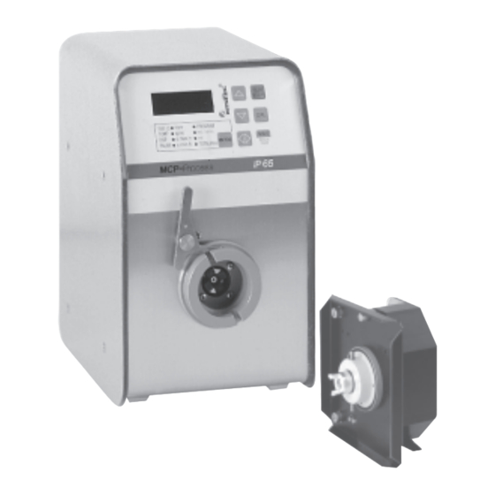
MCP Process
MCP Process/Ismatec SA/15.11.2000/CB/
GP
Pumpen-
Pump
Antrieb
drive
Mikroprozessor-
Microprocessor
gesteuert
controlled
Schutzgrad IP 65
Protection rating IP 65
ISM 915
ISM 915
Für Pumpenköpfe:
For pump-heads:
Pro 280 / Pro 281
Pro 280 / Pro 281
Pro 380 / Pro 381
Pro 380 / Pro 381
360 / 380 / 380 AD
360 / 380 / 380 AD
CA 4 / CA 8 / CA 12
CA 4 / CA 8 / CA 12
FMI Q0 / Q1 / Q2 / Q3
FMI Q0 / Q1 / Q2 / Q3
Easy-Load
Easy-Load
Standard
Standard
Quickload
Quickload
MS 3
MS 3
MS/CA 4-12 / MS/CA 8-6
MS/CA 4-12 / MS/CA 8-6
PTFE Membran HF/LF
PTFE Diaphragm HF/LF
PTFE Tube 2 mm / 4 mm
PTFE Tube 2 mm / 4 mm
SB 2V / 3V / 5V
SB 2V / 3V / 5V
SB 2V LP
SB 2V LP
WM 5
WM 5
Deutsch
English
Betriebsanleitung
Operating Manual
Mode d'emploi
Moteur de
pompe
Commandé par
microprocesseur
Classe de protection IP 65
ISM 915
Pour têtes de pompe:
Pro 280 / Pro 281
Pro 380 / Pro 381
360 / 380 / 380 AD
CA 4 / CA 8 / CA 12
FMI Q0 / Q1 / Q2 / Q3
Easy-Load
Standard
Quickload
MS 3
MS/CA 4-12 / MS/CA 8-6
PTFE Diaphragme HF/LF
PTFE Tube 2 mm / 4 mm
SB 2V / 3V / 5V
SB 2V LP
WM 5
Français
15.11.00
CB/GP
1
Advertisement
Chapters

Related Manuals for Idex ISMATEC MCP Process


Summary of Contents for Idex ISMATEC MCP Process
- Page 1 Pumpen- Pump Moteur de Antrieb drive pompe Mikroprozessor- Microprocessor Commandé par gesteuert controlled microprocesseur Schutzgrad IP 65 Protection rating IP 65 Classe de protection IP 65 MCP Process ISM 915 ISM 915 ISM 915 Für Pumpenköpfe: For pump-heads: Pour têtes de pompe: Pro 280 / Pro 281 Pro 280 / Pro 281 Pro 280 / Pro 281...
-
Page 2: Table Of Contents
Inhaltsverzeichnis Contents Sommaire Sicherheitsvorkehrungen 4–5 Safety precautions 4–5 Mesures de précaution 4–5 Garantiebestimmungen Warranty terms Conditions de garantie Produkt Product Produit Geräterückwand Rear panel Tableau arrière Netzspannung Mains voltage Tension d’alimentation Inbetriebnahme Starting the pump Mise en route Bedienungspanel Operating panel Tableau de commande Informations de Start-Information... - Page 3 Inhaltsverzeichnis Contents Sommaire Intervall-Dosieren Intermittent dispensing Dosage par intervalles nach Zeit by time de temps nach Volumen by volume de volume Nombre de cycles Anzahl Dosierzyklen No. of dispensing cycles de dosages Tropfenfreies Dosieren Drip-free dispensing Dosage sans goutte Pumpen gegen Druck Pumping against pressure Pompage contre pression Wenn die Pumpe ruht...
-
Page 4: Mesures De Précaution
Hinweis Sicherheitsvorkehrungen Safety precautions Mesures de précaution ® Wir empfehlen, diese Betriebs- Die Ismatec ® Pumpen sind für Ismatec Pumps are designed for Les pompes Ismatec ® sont prévues anleitung genau durchzulesen. Förderzwecke in Labors und der pumping applications in pour l’usage en laboratoire et Ismatec SA haftet nicht für laboratories and industry. - Page 5 Restrisiken Sicherheitsvorkehrungen Safety precautions Mesures de précaution Der Umgang mit Chemikalien liegt Manipulieren Sie nicht am Do not manipulate the pump- Ne manipulez jamais la tête de nicht im Verantwortungsbereich Pumpenkopf, bevor die Pumpe head before the pump is pompe avant que la pompe der Ismatec SA.
-
Page 6: Conditions De Garantie
Garantie Garantiebestimmungen Warranty terms Garantie Auf allen von Ismatec ® Wir garantieren eine einwand– We warrant the perfect Nous garantissons un fonc- hergestellten Erzeugnissen freie Funktion unserer Geräte, functioning of our products, tionnement impeccable de nos ab Lieferdatum: 2 Jahre appareils sous conditions d’une sofern diese sachgemäß... -
Page 7: Produit
Produkt Product Produit Packungsinhalt Contents of the package Emballage Antrieb MCP Process MCP Process drive Moteur MCP Process Bestell-Nr. ISM 915 Order No. ISM 915 No de commande ISM 915 inkl. fest montiertem Netzkabel incl. integrated power cord, y compris câble réseau fixe Länge 2 m, mit Geräte- 2 m long, with IEC 320 plug longueur 2 m, avec connexion... -
Page 8: Tableau Arrière
Geräterückwand Rear panel Tableau arrière 1 Netzschalter (ein/aus) 1 Mains switch (on/off) 1 Interrupteur principal 2 Netzkabel 2 Power cord 2 Prise d’alimentation 3 RS232 IN (Eingang, weiblich) 3 RS232 IN (female) 3 RS232 IN (entrée femelle) 4 RS232 OUT (Ausgang, männlich) 4 RS232 OUT (male) 4 RS232 OUT (sortie mâle) 5 Analog-Schnittstelle... -
Page 9: Mise En Route
Inbetriebnahme Starting the pump Mise en route Pumpenkopf gemäß separater Mount the pump-head Installer la tête de pompe Montageanleitung für according to the mounting selon le manuel d’utilisation Pumpenköpfe montieren instruction manual supplied fourni avec la tête de pompe. with the pump-head ID-Codes der verwendeten Saisir les numéros d’identifica- Pumpenköpfe in die... -
Page 10: Tableau De Commande
Bedienungspanel Operating panel Tableau de commande 1 Digitale LED-Anzeige 1 Digital LED display 1 Affichage digital à diodes 2 Wert reduzieren 2 Reduce value lumineuse 3 Wert erhöhen 3 Increase value 2 Réduire la valeur 4 Start / Stopp 4 Run / Stop 3 Augmenter la valeur 5 Kalibrieren / Speichern 5 Calibration / Data saving... -
Page 11: Informations De 11 Mise En Route
Start-Information Start-up information Informations de mise en route Die folgenden Einstellungen After switching on the power Les réglages suivants s’illuminent leuchten nach dem Einschalten supply switch, the following brièvement après la mise en des Netzschalters kurz auf: values are displayed: route de l’interrupteur de réseau: 1 LED-Test »8.8.8.8.«... -
Page 12: Remise Des Paramètres À
Die Parameter des aktuellen Resetting the parameters of Remise des paramètres du Programms auf ihre the currently used program programme actuel à leurs Default-Werte setzen. to the default values. valeurs par défaut. 1 Netzschalter »AUS« 1 Power switch »OFF« 1 Interrupteur principal sur »OFF«... -
Page 13: Touches De Commande
Steuertasten Control keys Touches de commande a RUN/STOP a RUN/STOP a RUN/STOP Pumpe starten bzw. stoppen Starts and stops the pump Mettre en route ou arrêter la STOP pompe b MODE b MODE b MODE Wechselt zwischen den Changes between operating Passage d'un mode d'opéra- Betriebsarten (siehe Seite 10) modes (see page 10) -
Page 14: Identification De La Tête De Pompe
Pumpenkopf-Identifikation Pump-head identification Identification de la tête de pompe Für korrekte Pump- und Dosier- In order to obtain correct Pour obtenir des valeurs Werte muss die richtige Pumpen- pumping and dispensing values correctes, il faut introduire le kopf-Identifikation (ID-Code) des the individual identification code code d‘identification de la tête de jeweils montierten Pumpenkopfes... -
Page 15: Saisie Du Diamètre De Tube Ou De L'angle De Course
Schlauch-Innendurchmesser Entering the tubing i.d. Saisie du diamètre de tube oder Hubwinkel eingeben or stroke angle ou de l'angle de course Für korrekte Fließraten und Before starting to pump it is Avant de mettre la pompe en Dosiervolumen sind vor Beginn essential to enter the following marche, il est indispensable de der Arbeit die nachstehenden... -
Page 16: Sélection Du Programme
Programmwahl Program selection Sélection du programme Beim Einschalten wählt die When switching the pump on, it Lors de l’enclenchement de la Pumpe immer das zuletzt always selects the previously pompe, cette dernière choisit benutzte Programm. used program. toujours le dernier programme utilisé. -
Page 17: Pompage Selon 17 Le Nombre De Tours
Pumpen nach Drehzahl Pumping by drive speed Pompage selon le nombre de tours 1 Mit der MODE-Taste auf 1 Change mode to PUMP rpm, 1 Passer sur PUMP rpm avec la TUBE I.D. PROGRAM PUMP Flow rate PUMP rpm, 1.0–240.0 min –1 1.0–240.0 rpm, adjustable in touche MODE,... -
Page 18: Le Débit
Pumpen nach Fließrate Pumping by flow rate Pompage selon le débit 1 Mit der MODE-Taste auf 1 Change mode to 1 Passer avec la touche MODE PUMP Flow rate PUMP Flow rate sur PUMP Flow rate TUBE I.D. PROGRAM PUMP Flow rate MODE DISP... -
Page 19: Calibration Du Débit
Fließrate kalibrieren Calibrating the flow rate Calibration du débit 1 Mit der MODE-Taste auf 1 Change mode to 1 Passer avec la touche MODE TUBE I.D. PROGRAM PUMP Flow rate PUMP Flow rate PUMP Flow rate sur PUMP Flow rate MODE DISP Time... -
Page 20: Dosage 20 Selon Le Temps
Dosieren nach Zeit Dispensing by time Dosage selon le temps TUBE I.D. PROGRAM Die Dosierzeit kann von The dispensing time can be La durée de dosage peut être PUMP Flow rate MODE 0.1s–999h eingegeben werden. entered from 0.1s to 999h. définie entre 0.1s –... -
Page 21: Selon Le Volume
Dosieren nach Volumen Dispensing by volume Dosage selon le volume 1 Mit der MODE-Taste auf 1 Change mode to 1 Passer avec la touche MODE TUBE I.D. PROGRAM PUMP Flow rate DISP Volume DISP Volume sur DISP Volume MODE DISP Time Volume PAUSE... -
Page 22: Calibration Du Volume
Volumen kalibrieren Calibrating the volume Calibration du volume TUBE I.D. PROGRAM 1 Mit MODE-Taste auf 1 Change MODE to 1 Passer avec la touche MODE PUMP Flow rate DISP Time Volume MODE DISP Volume DISP Volume sur DISP Volume PAUSE Time TOTAL ❖... -
Page 23: Calibration Par Défaut Du 23 Débit Ou Volume
Default-Kalibration Fließrate Calibrant reset of flow rate Calibration par défaut (débit) TUBE I.D. PROGRAM 1 Mit der MODE-Taste auf 1 Change mode to 1 Passer avec la touche MODE PUMP Flow rate MODE DISP Time Volume PUMP Flow rate PUMP Flow rate sur PUMP Flow rate PAUSE Time... -
Page 24: Dosage D'un Volume
Volumendosierung Dispensing by volume Dosage d'un volume dans un in einer Zeiteinheit within a pre-set time intervalle de temps donné TUBE I.D. PROGRAM PUMP Flow rate MODE 1 Mit der MODE-Taste auf 1 Change to mode 1 Passer avec la touche MODE DISP Time Volume... -
Page 25: Intermittent Dispensing
Intervall-Dosieren Intermittent dispensing Dosage par intervalles (Zeiteinheit) (by time) (unité de temps) TUBE I.D. PROGRAM Repetitives Dosieren nach Zeit Intermittent dispensing by time Dosage répétitif selon le temps PUMP Flow rate MODE mit vorgegebener Pausenzeit with a pre-set pause time avec un temps de pause DISP Time... -
Page 26: By Volume
Intervall-Dosieren Intermittent dispensing Dosage par intervalles (Volumen) (by volume) (selon volume) Repetitives Dosieren nach Intermittent dispensing by Dosage répétitif selon le Volumen mit vorgegebener volume with a pre-set pause volume avec un temps de Pausenzeit time pause prédéfini TUBE I.D. PROGRAM PUMP Flow rate... -
Page 27: Of Dispensing Cycles
Anzahl Dosierzyklen Number of dispensing cycles Nombre de cycles de dosage Beim Dosieren in Intervallen The number of dispensing Lors du dosage par intervalles (nach Zeit bzw. Volumen) kann cycles can be entered when (selon le temps, resp. le die Anzahl Dosierzyklen vorge- dispensing at intervals (by time volume), il est possible de geben werden. -
Page 28: Drip-Free Dispensing
Tropfenfreies Dosieren Drip-free dispensing Dosage sans goutte Mit programmierbaren Rollen- With programmable roller back- Avec des pas arrière programma- rückschritten bzw. Kolbenhub- steps or piston stroke back-steps bles (des galets ou des courses de Rückschritten (beim FMI Pumpen- (FMI pump-head) (1–100 steps or pistons {tête de pompe FMI}) kopf) (1–100 Schritte bzw. -
Page 29: Pumping Against Pressure
Hinweis Pumpen gegen Druck Pumping against pressure Pompage contre pression Die MCP Process kann im The MCP Process can be used for En exploitation continue, le Druckregelungs-Einheit siehe Dauerbetrieb bis max. 1.5 bar continuous duty at a differential moteur MCP Process peut être Seite 42. -
Page 30: Protection De Surcharge
Überlastschutz Overcurrent protector Protection de surcharge Der Antrieb MCP Process verfügt The drive MCP Process La pompe IP possède une über eine Überlast-Sicherung. features a an overload protector. protection de surcharge. Une état Eine Überlastung wird im Display When an overload condition illégal est indiqué... -
Page 31: Running-In Period
Hinweis Einlaufzeit der Schläuche Running-in period for tubing Durée de rodage des tubes Jeder neue Schlauch braucht eine Every new tube requires a Chaque nouveau tube a besoin Wir verweisen auf unsere Einlaufzeit. running-in period. d’un temps de rodage ausführliche Schlauch- dokumentation. -
Page 32: Interface Analogique
Analogschnittstelle Analog interface Interface analogique Pin 1, GND (Masse) Pin 1, GND (ground) Pin 1, GND (masse) speed IN direction input 1 start Bezugspotential für alle anderen Reference potential for all other Potentiel de référence pour +26VDC remote Eingänge. inputs toutes les autres entrées input 2 8 7 6 5 4 3 2 1... -
Page 33: Dc / 0-10 Vdc
Analogschnittstelle Analog interface Interface analogique Pin 9, speed OUT Pin 9, speed OUT Pin 9, speed OUT speed IN direction input 1 start Die werkseitige Einstellung ist The default setting is 0–10 V Le réglage d’usine par défaut est +26VDC remote 0–10 V , proportional zur... -
Page 34: Foot-Switch
Einstellungen Schalter S1 Settings of switch S1 Réglages du switch S1 Fußschalter-Betrieb Operation via foot-switch Exploitation par le biais de la Mit DIP-Switch 5 kann zwischen With DIP switch 5 the user can pédale de commande zwei Möglichkeiten gewählt switch between two possibilities: Avec le DIP switch 5, l’utilisateur werden: - »FS toggle«... -
Page 35: Interface Sérielle
Hinweis Serielle Schnittstelle Serial interface Interface sérielle Der Antrieb MCP Process hat beim RS232 IN (Eingang, weiblich) RS232 IN (female) RS232 IN (entrée femelle) Einschalten eine Verzögerung von Der Anschluss erfolgt über eine A 9-pin D-socket is available on Le raccordement se fait par le 3 Sekunden, bis die serielle 9-polige D-Buchse. - Page 36 Serielle Schnittstelle / Serial interface / Interface sérielle Pumpensoftware Version Zeichenerklärungen / Key to the symbols / Explications des signes 1.01 Pump software version Eingabe richtig/Correct input/Saisie correcte Version du logiciel de la pompe Eingabe falsch/Incorrect input/Saisie erronée Microsoft Windows Visual Basic _ _ _ _ Ziffern zwischen 0–9/Numerals between 0–9/Chiffres entre 0–9 kann zur Programmierung der nachstehenden Befehle angewendet werden.
-
Page 37: Input
Serielle Schnittstelle / Serial interface / Interface sérielle Befehl Funktion / Beschreibung Beispiel Antwort Command Function / Description Example Response Commande Fonction / Description Exemple Réponse 1D-12.3 13 D_ _ _ _ _ Zahlen für Bedienfeld schreiben (nur bei inaktivem Bedienfeld sichtbar, siehe Befehl B) 1D12.34 13 Writing numbers for control panel (only visible if control panel is inactive, see command B) Ecrire les chiffres pour le panneau de commande (visible uniquement lorsque le panneau est inactif, voir commande B) -
Page 38: Input
Serielle Schnittstelle / Serial interface / Interface sérielle Befehl Funktion / Beschreibung Beispiel Antwort Command Function / Description Example Response Commande Fonction / Description Exemple Réponse 1+0320 13 +_ _ _ _ Eingabe: Pumpenschlauch Innendurchmesser (in Input: Pump tubing inner diameter (in Saisie: Diamètre intérieur du tube de pompe (en 1S 13... - Page 39 Serielle Schnittstelle / Serial interface / Interface sérielle Befehl Funktion / Beschreibung Beispiel Antwort Command Function / Description Example Response Commande Fonction / Description Exemple Réponse 1[02500 13 [_ _ _ _ _ Eingabe: Dosiervolumen in ml für »MODE DISP Volume« (Anzahl Stellen nach dem Komma richten sich nach Pumpenkopf und Schlauch) (Das eingegebene Dosiervolumen wird auf ganze Rollenschritte abgerundet) Input:...
- Page 40 Serielle Schnittstelle / Serial interface / Interface sérielle Befehl Funktion / Beschreibung Beispiel Antwort Command Function / Description Example Response Commande Fonction / Description Exemple Réponse 1\0002 13 \000_ Eingabe: Default-Werte für gewünschtes (1–4) Programm setzen Input: Set default values for required program (1–4) Saisie: Définir les valeurs par défaut pour le programme souhaité...
-
Page 41: Montage En Cascade De Plusieurs Pompes
Kaskadierung Cascading Montage en cascade mehrerer Pumpen several pumps de plusieurs pompes Sofern Sie über eine entsprechen- Providing that an appropriate Si vous êtes en possession d‘un de Software verfügen, können bis software is available, up to logiciel adéquat, il vous est max. -
Page 42: Logiciel Pour Programmer
Programmier-Software Programming Software Logiciel de programmation Software ProgEdit Software ProgEdit Logiciel ProgEdit Kreieren Sie Ihre individuelle Create your individual Créez votre programme Programm-Applikation am PC. application program. d'application individuel. Laden Sie diese via RS232- Download the program via Chargez le programme sur Schnittstelle in Ihre MCP RS232 interface to your MCP votre moteur MCP Process par... -
Page 43: Carte D'interface
Zubehör Accessories Accessoires IM0015C168 Moxa C168 Schnittstellenkarte Moxa C168 nterface card Moxa C168 Carte d’interface Moxa C168 inkl. 25 poliges (male) Mehrfach- including a 25 pin multiple cable incluant un câble multiple avec max. 8 Pumpen kabel zur Steuerung von max. (male) for controlling up to 8 fiches 25 pôles (mâle) pour pumps... -
Page 44: Cassettes De Rechange
Zubehör Accessories Accessoires Ersatz-Kassetten aus POM Spare-cassettes in POM Cassettes de rechange en POM MS/CA Click'n'go MS/CA Click'n'go MS/CA Click'n'go Bestell-Nr. IS 3510 Order No. IS 3510 No de commande IS 3510 MS/CA Anpresshebel MS/CA pressure lever MS/CA levier de pression Bestell-Nr. -
Page 45: Interchangeables
Montage Pumpenköpfe Pump-heads Têtes de pompe Auswechselbare Interchangeable interchangeables Jedem Pumpenkopf liegt eine Diese Pumpenköpfe können These pump-heads can be Ces têtes de pompe peuvent être Montageanleitung bei. einzeln bestellt und am Antrieb ordered separately and mounted commandées séparément et Vor Inbetriebnahme den korrekten MCP-Standard montiert werden. - Page 46 ID-No.: Pumpenkopf-Identifikation / Pump-head identification / Identification des têtes de pompe Muss in allen mit dem jeweiligen Pumpenkopf Must be entered for each of the 4 programs Doit être saisi dans tous les programmes verwendeten Programmen eingegeben werden. using the particular pump-head. utilisés avec la tête de pompe correspondante.
-
Page 47: Flow Rates Charts
Hinweis Fließraten-Tabellen / Flow rate charts / Tableaux des débits Bei den Angaben in den nachfol- genden Tabellen handelt es sich nur um Richtwerte, die wie folgt Pumpenkanäle 2 – 1 – ermittelt wurden: e l l ml/min, pro Kanal, mit Wasser und e l l e l l Tygon... - Page 48 Pumpenkanäle t è t è é r t è t è t è t è t è – Ø ß ß ß ß ß ß ß ß é s t i é s t i é s t i é s t i é...
- Page 49 Hinweis Fließraten-Tabellen / Flow rate charts / Tableaux des débits Bei den Angaben in den nachfol- genden Tabellen handelt es sich nur um Richtwerte, die wie folgt Pumpenkanäle ermittelt wurden: ml/min, pro Kanal, mit Wasser und Tygon ® -Schlauch, ohne Differenz- è...
-
Page 50: Ouverture Du Boîtier
Öffnen der Gehäusehaube Opening the casing hood Ouverture du boîtier Um die Dichtigkeit des In order to maintain the best Afin de garantir l’étanchéité Gehäuses zu gewährleisten, possible seal of the casing, the du boîtier, il est recommandé de empfehlen wir, die Pumpe nur für pump should only be opened for n’ouvrir la pompe que pour das Ersetzen einer Sicherung oder... -
Page 51: Etanchéité De La Prise
Öffnen der Gehäusehaube Opening the casing hood Ouverture du boîtier Abdichten der Haube Sealing the casing hood Etanchement du capot Wenn die Haube gut sitzt, muss When the casing hood fits tight, Lorsque le capot est bien en jede Schraube (einzeln!) erneut each single screw must be place, chaque vis (une à... -
Page 52: Remplacement Des Fusibles
Auswechseln der Sicherungen Changing the fuses Remplacement des fusibles Die Sicherungen sind auf dem The fuses are fixed to the control Les fusibles sont fixés sur le Steuerprint (oben) und auf dem board (above) and the power tableau de commande (dessus) et Netzteilprint (unten) wie supply print (below) as illustrated sur le tableau réseau (dessous) -
Page 53: Entretien / Réparation
Unterhalt Maintenance Maintenance Sofern die MCP Process bestim- Provided the MCP Process is Pour autant que le moteur MCP mungsgemäß und mit der nöti- operated properly and in Process soit utilisé avec tout le gen Sorgfalt eingesetzt wird, compliance with this manual, the soin nécessaire et conformément unterliegt lediglich das Schlauch- tubing is the only part that is... -
Page 54: Spécifications Techniques
Hinweis Technische Daten Technical Specifications Spécifications techniques Beachten Sie ebenfalls unsere Antrieb Drive Moteur Garantie- und allgemeinen Ver- Motortyp DC-Motor Motor type DC motor Type de moteur moteur DC kaufs- und Lieferbedingungen. –1 Drehzahlbereich 1.0–240.0 min Speed range 1.0–240.0 rpm Vitesse 1.0–240.0 t/min digital einstellbar in... -
Page 55: Mode D'emploi Abrégé
Program selection / Programm wählen Dispensing by volume within a pre-set time Volumen dosieren in einer Zeiteinheit PROGRAM DISP Time DISP Volume Pump-head identification / Pumpenkopf-ID MODE DISP Time Volume STOP Error DISP Time Volume Volume too large, time too short Tubing i.d./Stroke angle / Schlauch iØ/Hubwinkel 9999 Volumen zu groß, Zeit zu kurz... - Page 56 Ismatec ® - Vertretung Representative/Représentation ISMATEC SA Labortechnik - Analytik A Unit of IDEX Corporation Feldeggstrasse 6 P.O. Box CH-8152 Glattbrugg-Zürich Switzerland Phone 41 (0)1 874 94 94 41 (0)1 810 52 92 E-Mail sales@ismatec.ch Internet www.ismatec.com ISMATEC Laboratoriumstechnik GmbH A Unit of IDEX Corporation Futtererstraße 16...
Need help?
Do you have a question about the ISMATEC MCP Process and is the answer not in the manual?
Questions and answers