
Related Manuals for IFM AL1060


Summary of Contents for IFM AL1060
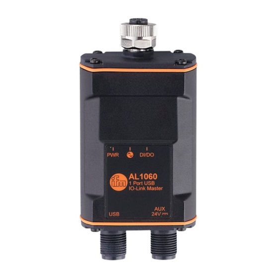
- Page 1 > > Operating instructions IO-Link master with USB interface 1 port IP 65 / IP 67 AL1060 Firmware: 3.2.x English...
- Page 2 IO-Link master with USB interface 1 port IP 65 / IP 67 Contents Vorbemerkung Symbols used ........................4 Warnings used ........................4 Modification history ......................5 Safety instructions Functions and features Function IO-Link ..........................8 4.1.1 IO-Link supply ..........................8 Additional digital input / output .....................
- Page 3 IO-Link master with USB interface 1 port IP 65 / IP 67 Port 1: Configuring operating mode pin 2 ................19 Info: Showing device information ..................19 Firmware: Reseting device to factory settings ..............19 Firmware: Rebooting the device ..................20 IO-Link device: Accessing parameter values ..............20 Troubleshooting Maintenance, repair and disposal 11.1...
- Page 4 Preliminary note Content Symbols used ............................4 Warnings used ............................4 Modification history ........................... 5 60846 Technical data, approvals, accessories and further information at www.ifm.com > Symbols used 58277 Important note Non-compliance can result in malfunction or interference Information Supplementary note ►...
- Page 5 IO-Link master with USB interface 1 port IP 65 / IP 67 > Modification history 34492 Version Topic Date New creation of document 10 / 2020 Added: note on additional power supply 11 / 2020 Corrected: max. current of IO-Link devices Corrected: minimum requirements: Windows 10 04 / 2021...
- Page 6 IO-Link master with USB interface 1 port IP 65 / IP 67 Safety instructions 60809 • The device described can be installed as a subcomponent in a system. The system architect is responsible for the safety of the system. The system architect undertakes to perform a risk assessment and to create documentation in accordance with legal and normative requirements to be provided to the operator and user of the system.
- Page 7 IO-Link master with USB interface 1 port IP 65 / IP 67 Intended use 60810 The device may only be used for the following purposes: • As an IO-Link master to configure and control the connected IO-Link device • As a gateway between an IO-Link device and a computer The device is designed for use outside of a control cabinet.
- Page 8 IO-Link master with USB interface 1 port IP 65 / IP 67 Function Content IO-Link ..............................8 Additional digital input / output ......................... 8 Visual indication ............................8 Parameter setting ............................. 8 33836 > IO-Link 60811 The device offers the following IO-Link functions: •...
- Page 9 IO-Link master with USB interface 1 port IP 65 / IP 67 Installation Content Install the device ............................9 60816 The responsibility for the compliance with the requirements concerning mounting of the device in the application with regard to shock, vibration, acceleration and weight lies with the system architect.
- Page 10 IO-Link master with USB interface 1 port IP 65 / IP 67 Electrical connection Content Overview ..............................11 IO-Link Device anschließen........................11 Connect the device ..........................11 60818 The device must be connected by a qualified electrician. ► The national and international regulations for the installation of electrical equipment must be adhered to.
- Page 11 IO-Link master with USB interface 1 port IP 65 / IP 67 > Overview 60819 IO-Link port AUX port USB port > Connecting the IO-Link device 60858 ► Connect the IO-Link device to the M12 socket of the IO-Link port. ▪...
- Page 12 IO-Link master with USB interface 1 port IP 65 / IP 67 Operating and display elements Content LED: PWR ..............................12 LED: IO-Link ............................12 LED: DI/DO .............................12 34063 > LED: PWR 60821 The LED “PWR” indicates the status of the voltage supply. Status LED Colour Status...
- Page 13 Installing LR DEVICE 60825 The ifm software LR DEVICE (version 1.7.x or higher, art. no. QA0011/12) is required to configure the IO-Link master and the connected IO-Link device. For basic functions of the LR DEVICE software: → Software manual LR DEVICE ►...
-
Page 14: Table Of Contents
► Click on the [Read from device] symbol. > LR DEVICE searches for connected devices. > LR DEVICE displays the IO-Link master AL1060 under [ONLINE]. ► In the [ONLINE] area, click on the IO-Link master. > LR DEVICE displays a detailed view of the IO-Link master. - Page 15 The AL1060 supports offline parameter setting. The user creates a configuration for the IO-Link master and the connected IO-Link devices without being connected to the AL1060 (OFFLINE mode). The configuration created in this way can be stored as a file (*.lrp) and loaded to the AL1060 and activated at a later point.
-
Page 16: Port 1: Configure Operating Mode Pin 4
IO-Link master with USB interface 1 port IP 65 / IP 67 > Port 1: Configuring operating mode pin 4 60830 Pin 4 (C/Q) of the IO-Links port supports the following operating modes: • Disabled: no data transmission • Digital input (DI): digital input signal •... -
Page 17: Port 1: Configure Device Validation And Data Storage
IO-Link master with USB interface 1 port IP 65 / IP 67 > Port 1: Configuring device validation and data storage 60831 In the "IO-Link" operating mode, the IO-Link port offers the following functions: • Storage of the IO-Link device configuration for automatic recovery (data storage) •... - Page 18 IO-Link master with USB interface 1 port IP 65 / IP 67 > 9.3.1 Note: Device validation and data storage 60832 The user can choose how the IO-Link ports are to behave with regards to the device validation and the storage / recovery of parameter data of the connected IO-Link device.
-
Page 19: Port 1: Configure Operating Mode Pin 2
Digital input Digital output ► Save changed values on the device. > Info: Showing device information 60834 To read the general information of the ifm IO-Link master: ► Select [Info] menu. > The menu page shows the current settings. Name Description... -
Page 20: Firmware: Reboot The Device
> The menu page shows the current settings. ► Click on [Reboot] to reboot the device. > LR DEVICE reboots the ifm IO-Link master. > IO-Link device: Accessing parameter values 60837 To access the IO-Link device connected to the IO-Link master: Information about the available parameters and data structures of the IO-Link device: →... - Page 21 IO-Link master with USB interface 1 port IP 65 / IP 67 Troubleshooting 60838 Warnings, faults and status messages are indicated by the status LEDs (→ Operating and display elements (→ p. 12)). LR DEVICE provides additional status information in the online mode (→ LR DEVICE software manual).
- Page 22 If the additional voltage supply is disconnected from port "AUX”, the device reboots. ► Make sure that the firmware update is not interrupted. Requirements: • New firmware file has been downloaded (→ www.ifm.com). • New firmware file has been unzipped (*.bin). ► Start LR DEVICE.
Need help?
Do you have a question about the AL1060 and is the answer not in the manual?
Questions and answers