Table of Contents
Advertisement
Quick Links
Advertisement
Table of Contents

Related Manuals for IFM AL1060


Summary of Contents for IFM AL1060
- Page 1 Operating instructions IO-Link master with USB interface AL1060...
-
Page 2: Table Of Contents
AL1060 IO-Link master with USB interface Contents Preliminary note ............. -
Page 3: Preliminary Note
IO-Link master with USB interface AL1060 1 Preliminary note You will find instructions, technical data, approvals and further information using the QR code on the unit / packaging or at documentation.ifm.com. 1.1 Symbols used Requirement Instructions Reaction, result [...] Designation of keys, buttons or indications... -
Page 4: Safety Instructions
AL1060 IO-Link master with USB interface 2 Safety instructions • The unit described is a subcomponent for integration into a system. – The system architect is responsible for the safety of the system. – The system architect undertakes to perform a risk assessment and to create documentation in accordance with legal and normative requirements to be provided to the operator and user of the system. -
Page 5: Intended Use
IO-Link master with USB interface AL1060 3 Intended use The device may only be used for the following purposes: • IO-Link master for configuration, management and operation of IO-Link devices • As a gateway between an IO-Link device and the USB interface of a computer... -
Page 6: Function
Status of the voltage supply • Status of the IO-Link port • Status of the digital input / output 4.4 Parameter setting The device offers the following configuration options: • Parameter setting software – ifm moneo OS + ifm moneo|configure – ifm moneo|configure SA... -
Page 7: Installation
IO-Link master with USB interface AL1060 5 Installation 5.1 Installing the device The following applies to all types of mounting: The responsibility for the compliance with the requirements concerning mounting of the device in the application with regard to shock, vibration, acceleration and weight lies with the system architect. -
Page 8: Electrical Connection
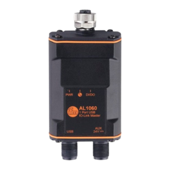
AL1060 IO-Link master with USB interface 6 Electrical connection 6.1 Overview 1: IO-Link port 2: AUX port 3: USB port 6.2 General wiring information The device must be connected by a qualified electrician. u Observe the national and international regulations for the installation of electrical equipment. -
Page 9: Voltage Supply
IO-Link master with USB interface AL1060 Sensor supply (US) L+ Digital input / output Sensor supply (US) L- IO-Link (C/Q) Not used u Connect the IO-Link device to the IO-Link port. Max. cable length: 20 m u For connection, use an M12 connector (minimum protection rating: IP 66 / IP 67). -
Page 10: Operating And Display Elements
AL1060 IO-Link master with USB interface 7 Operating and display elements 7.1 LEDs 1: PWR 3: DI/DO 7.1.1 Voltage supply Description Colour State Description Voltage supply sta- No supply voltage applied Green Supply voltage applied (USB or power supply) Supply voltage of the power supply insufficient or faulty / short circuit 7.1.2 IO-Link port... -
Page 11: Set-Up
A parameter setting software is required to configure the IO-Link master and the connected IO-Link device. Supported parameter setting software: • ifm moneo OS (art. no. QMS001) + module licence ifm moneo|configure (art. no. QMP020) • ifm moneo|configure SA (art. no. QMP010) u For correct installation: observe the installation instructions for ifm moneo. -
Page 12: Parameter Setting
In the [Actions] column: Click on . w Connecting to device. w The connected IO-Link device is detected. Fig. 1: IO-Link master with connected IO-Link device (example: AL1060 with sensor MVQ101) To configure the IO-Link master: u In the Actions column: Click on . -
Page 13: Online Parameter Setting
IO-Link master with USB interface AL1060 Fig. 2: Parameter value editor of AL1060 9.1.1 Online parameter setting The device supports online parameter setting. The parameters of the IO-Link master and the connected IO-Link devices can be set during operation. Changing parameters during operation will influence the behaviour of the plant. -
Page 14: Port 1: Setting The Operating Mode Of Pin 4
AL1060 IO-Link master with USB interface u Set the application-specific tag. u Save the changes on the device. w Application-specific tag is active. 9.3 Port 1: setting the operating mode of pin 4 Pin 4 of the port supports the following operating modes: •... -
Page 15: Port 1: Setting The Device Validation And Data Storage
IO-Link master with USB interface AL1060 read only; Parameter only available if operating mode pin 4 (US) = IO-Link and IO-Link device is connected to port To set the cycle time of the IO-Link data transmission: Requirements: ü The parameter setting software has been started. -
Page 16: Port 1: Setting The Operating Mode Of Pin 2
AL1060 IO-Link master with USB interface Parameter Description Value range Access [Port 1 Validation / Data Device validation and data storage • No check and clear: validation Storage] functions for backing up and restoring deactivated; data storage functions parameter sets of the connected IO-... -
Page 17: Info: Reading Device Information
IO-Link master with USB interface AL1060 u Save the changes on the device. w The set operating mode is active. 9.7 Info: Reading device information Available information: Name Description Value range Access Product code Article number AL1060 Device family Family of the device... -
Page 18: Firmware: Showing The Firmware Version
AL1060 IO-Link master with USB interface 9.9 Firmware: Showing the firmware version Available parameters: Parameter Description Value range Access Version Firmware version e.g., AL1x6x_cn_ub_v3.2.6 Read only Requirements: ü The parameter setting software has been started. ü The connection to the device has been established. -
Page 19: Troubleshooting
IO-Link master with USB interface AL1060 10 Troubleshooting Errors, warnings and status messages are indicated by the status LEDs: Operating and display elements (Ò / 10) Additional status information is provided by the parameter setting software in online mode (Ò user documentation of the parameter setting software). -
Page 20: Maintenance, Repair And Disposal
AL1060 IO-Link master with USB interface 11 Maintenance, repair and disposal The operation of the unit is maintenance-free. u Dispose of the device in an environmentally friendly way in accordance with the applicable national regulations when it is no longer used.