
Related Manuals for Keithley DAC-02


Summary of Contents for Keithley DAC-02
- Page 1 (217) 352-9330 | Click HERE Find the Keithley DAC-02 at our website:...
- Page 2 DAC-02 User’s Guide A G R E A T E R M E A S U R E O F C O N F I D E N C E Artisan Technology Group - Quality Instrumentation ... Guaranteed | (888) 88-SOURCE | www.artisantg.com...
- Page 3 Hardware Keithley Instruments, Inc. warrants that, for a period of one (1) year from the date of shipment (3 years for Models 2000, 2001, 2002, 2010 and 2700), the Keithley Hardware product will be free from defects in materials or workmanship. This warranty will be honored provided the defect has not been caused by use of the Keithley Hardware not in accordance with the instructions for the product.
- Page 4 EXCEPT FOR THE EXPRESS WARRANTIES ABOVE KEITHLEY DISCLAIMS ALL OTHER WARRANTIES, EXPRESS OR IMPLIED, INCLUDING WITHOUT LIMITATION, ALL IMPLIED WARRANTIES OF MERCHANT- ABILITY AND FITNESS FOR A PARTICULAR PURPOSE. KEITHLEY DISCLAIMS ALL WARRANTIES WITH RESPECT TO THE OTHER HARDWARE AND OTHER SOFTWARE.
- Page 5 DAC-02 User’s Guide Revision B - July 1994 Part Number: 61740 Artisan Technology Group - Quality Instrumentation ... Guaranteed | (888) 88-SOURCE | www.artisantg.com...
- Page 6 Keithley Instruments, Inc. 28775 Aurora Road Cleveland, OH 44139 Technical Support: 1-888-KEITHLEY Monday – Friday 8:00 a.m. to 5:00 p.m (EST) Fax: (440) 248-6168 Visit our website at http://www.keithley.com Artisan Technology Group - Quality Instrumentation ... Guaranteed | (888) 88-SOURCE | www.artisantg.com...
- Page 7 Keithley products are designed for use with electrical signals that are rated Installation Category I and Installation Category II, as described in the International Electrotechnical Commission (IEC) Standard IEC 60664. Most mea- surement, control, and data I/O signals are Installation Category I and must not be directly connected to mains voltage or to voltage sources with high transient over-voltages.
- Page 8 (Note that selected parts should be purchased only through Keithley Instruments to maintain accuracy and functionality of the product.) If you are unsure about the applicability of a replacement component, call a Keithley Instruments office for information.
- Page 9 The information contained in this manual is believed to be accurate and reliable. However, Keithley Instruments, Inc., assumes no responsibility for its use or for any infringements of patents or other rights of third parties that may result from its use. No license is granted by implication or otherwise under any patent rights of Keithley Instruments, Inc.
-
Page 10: Table Of Contents
Table of Contents Preface Overview Features and Applications ......1-1 Supporting Software ........1-2 Accessories . - Page 11 List of Figures Figure 2-1. Block Diagram of DAC-02 ....2-1 Figure 3-1. Base Address Switch Location ....3-3 Figure 4-1.
-
Page 12: Preface
Preface The DAC-02 User’s Guide is intended to help you understand the installation, interface requirements, functions, and operation of the DAC-02 board. This guide focuses primarily on describing the board and its capabilities, setting up the board and its associated software, making typical hookups, and operating the Control Panel software. - Page 13 Chapter 8 contains information on isolating and determining the source of operating problems. This chapter also contains instructions for obtaining technical support. Appendix A contains specifications for the DAC-02 board. Appendix B contains pin assignments for the main I/O connector of the DAC-02 board.
-
Page 14: Overview
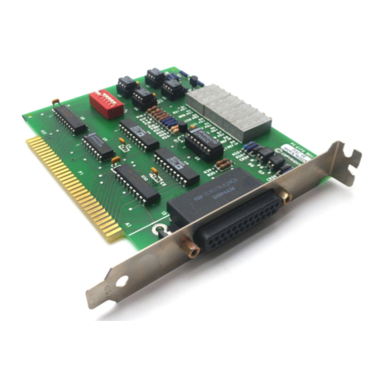
Overview The DAC-02 is a 2-channel, 12-bit analog output board packaged in a 5-inch, half-slot length suitable for an accessory slot of an IBM PC/XT, PC AT, or compatible computer. This chapter lists features and applications of the board and describes supporting software and accessories. -
Page 15: Supporting Software
Supporting Software The software package for the DAC-02 is provided on 3.5-inch or 5.25-inch diskettes. This package includes example programs in ® ™ Microsoft QuickBasic 4.5, Microsoft Professional BASIC, C, Pascal, ™ ™ and Microsoft Visual Basic for Windows . The package also includes support files and the following utility programs:... -
Page 16: Functional Description
This chapter describes the features of the DAC-02 board to familiarize you with the operating options and to enable you to make the best use of your board. Figure 2-1 shows a block diagram of the DAC-02 board. −10 V V Ref −5 V... - Page 17 The DAC-02 board consists of two separate, double-buffered, 12-bit, multiplying DACs (digital-to-analog converters) and interface circuitry. The DACs can operate as conventional D/A (digital-to-analog) converters if they are used with a fixed DC reference. Using the DACs with the −...
-
Page 18: Setup And Installation
Use the following procedure to unwrap and inspect a DAC-02 board. 1. Factory packaging of the DAC-02 board includes a final wrap of protective, anti-static material. Remove the board from its anti-static wrapping material. You may wish to store the wrapping material for possible future use. -
Page 19: Installing The Software Package
Note that the Windows program CTL02W.EXE, the Control Panel , is available for the operation of your DAC-02. If you plan to use the Control Panel, read the text file README.TXT for installation instructions. If you plan to use the PORTIO.DLL to write applications in Visual Basic for Windows for... -
Page 20: Figure 3-1. Base Address Switch Location
Base Address Switch 1 2 3 4 5 6 Figure 3-1. Base Address Switch Location The base address switch is preset at the factory for 300h (see Figure 3-1). Check this setting against the needs of your application to be sure you have no conflicts. -
Page 21: Table 3-2. Standard Address Assignments
The address you specify must be within the range of 200 to 3F8h (512 to 1008 decimal) and on a 8-byte boundary. When selecting a base address, do not select an address that conflicts with those already in use. Table 3-2 lists standard address assignments and their corresponding devices. -
Page 22: Installing The Board
Installing or removing a board while power is on can damage your computer. Use the following steps to install a DAC-02 board in an accessory slot of your computer: 1. Turn off power to the computer and all attached equipment. -
Page 23: Cabling And Wiring
Cabling and Wiring This chapter shows the attachments you can add to the main I/O connector of your DAC-02 board. The main I/O connector of the DAC-02 is a 25-pin, D-type. Pin assignments for this connector are shown in Figure 4-1. -
Page 24: Attaching An Sta-U
Attaching an STA-U To attach an STA-U accessory to the DAC-02, use a K-1800 cable, as shown in Figure 4-2. DAC-02 board STA-U K-1800 cable Figure 4-2. Attaching an STA-U Selecting Output Ranges You select the output range of each DAC by jumpering pins on the mating connector for the main I/O connector or on the STA-U. -
Page 25: Using The 4 To 20 Ma Current Loop Output
Table 4-1. Pin Wiring for Output Ranges (cont.) Range DAC # Jumper Pins Output ±10 V 20 to 22 Pin 23 14 to 16 Pin 17 4 to 20 mA 21 to 22 Pin 25 15 to 16 Pin 19 AC Reference In on pin 22 Pin 24 (2-quadrant) -
Page 26: Figure 4-4. 4 To 20 Ma Current Output (Floating Load)
A 24 or 36 V supply is ideal. Figures 4-4 and 4-5 shows two ways of connecting the process loop. The floating-load way allows additional loops to be powered by the same supply but constrains the load to 2-wire floating. DAC-02 Other Loops 4 to 20 mA... -
Page 27: Using An Ac Reference (Digital Attenuator)
Figure 4-5. 4 to 20 mA Current Output (Grounded Load) Using an AC Reference (Digital Attenuator) In addition to its uses as a standard DC output DAC, the DAC-02 can be used with a bipolar or AC reference signal. Figure 4-6 shows the equivalent circuit for the board when used in this mode. - Page 28 The customary terminology for operation of a DAC-02 differs when you use an AC reference. If you take the output from the unipolar terminals, you get 2-quadrant operation because the reference, which may be positive or negative, is multiplied with a signal that is positive only. If you...
-
Page 29: The Control Panel
The Control Panel The Control Panel is a utility program (CTL02W.EXE) for testing the functions of your DAC-02 boards in the Windows environment. This program is a part of the DAC-02 software package. To use the Control Panel, perform the following steps: 1. -
Page 30: Programming
I/O commands. I/O Address Map The DAC-02 uses eight consecutive addresses in the I/O address space of the computer. The board’s base address (Base Address +0h) determines where the registers of the board are located in the I/O space. Table 6-1 is a map of the DAC-02 register I/O addresses. -
Page 31: Data Format
Data Format The 12-bit data is written to each DAC in two consecutive bytes. The first byte contains the four LSBs (least significant bits) of data. The second byte contains the eight MSBs (most significant bits) of data. The format of this data is shown in Table 6-2. -
Page 32: Programming Examples
Programming Examples The following example shows how to output data in BASIC. The example is in BASIC but translates readily into other programming languages. Since the DACs have 12-bit resolution, data D should be in the range 0 to 4095 decimal. First, split the data into the two bytes DL% (low) and DH% (high), as follows: 05 DH% = INT(D/16) ’Generate high byte... -
Page 33: Calibration
Calibration Your DAC-02 board is initially calibrated at the factory. You are advised to check the calibration of a board periodically. For laboratory environments, a 6-month to 1-year calibration interval is recommended. For extremes of temperature, vibration, and humidity, a 3-month calibration interval is recommended. -
Page 34: Troubleshooting
“Technical Support” on page 8-5 for information on how to contact an applications engineer. Problem Isolation If you encounter a problem with a DAC-02 board, use the instructions in this section to isolate the cause of the problem before calling Keithley MetraByte Hardware Applications Engineering. -
Page 35: Table 8-1. Troubleshooting Information
The board is incorrectly aligned Check the board for proper seating. in the accessory slot. The board is damaged. Contact the Keithley MetraByte Hardware Applications Engineering Department; see page 8-5. Intermittent The most common cause of this Reduce I/O bus speed to a maximum of... - Page 36 An open connection exists. Check wiring to screw terminal. Another system resource is using Reconfigure the base address of the DAC-02 the specified base address. board; refer to page 3-3 for more information. Check the I/O assignments of other system resources and reconfigure, if necessary.
-
Page 37: Testing The Board And Host Computer
Testing the Board and Host Computer To isolate the problem to the DAC-02 board or to the host computer, perform the following steps: 1. Turn the power to the host computer OFF, and remove power connections to the computer. Removing a board with the power ON can cause damage to Caution: your board and/or computer. -
Page 38: Technical Support
5. If operation remains normal to this point, the problem is in the DAC-02 board(s) originally in the computer. If you were using more than one board, try each board one at a time in the computer to determine which is faulty. - Page 39 Please make sure that you have the following information available before you call: DAC-02 Board Model ___________________ Configuration Serial # ___________________ Revision code ___________________ Base address setting ___________________ Number of channels ___________________ ___________________ Computer Manufacturer ___________________ CPU type ___________________ Clock speed (MHz)
- Page 40 Notes: you must include the invoice number and date of purchase. To enable Keithley Metrabyte to respond as quickly as possible, you must include the RMA number on the outside of the package. Artisan Technology Group - Quality Instrumentation ... Guaranteed | (888) 88-SOURCE | www.artisantg.com...
-
Page 41: Specifications
Specifications This appendix provides specifications for the DAC-02 board. Table A-1. DAC-02 Specifications Feature Specification Channels Resolution 12 bits (1 part in 4096 decimal) Relative accuracy 1/2 LSB (0.01%) maximum Differential linearity 1/2 LSB maximum Fixed reference ranges 0 to 5 V (unipolar) 0 to 10 V (unipolar) ±5 V (bipolar) - Page 42 Table A-2. Environmental Specifications Feature Specification Temperature coefficient ±25 ppm/˚ C (with reference) of gain ±5ppm/˚ C (external reference) Zero drift ±3 ppm/˚ C Operating temperature 0 to 70˚ C range − 55 to +125˚ C Storage temperature range Humidity 0 to 95% noncondensing Weight 4 oz.
-
Page 43: Connector Pin Assignments
Connector Pin Assignments The connection between an external I/O device and a DAC-02 board is made at the main I/O connector, which is a standard 25-pin, D-type male connector. The mating connector is a 25-pin, D-type female connector. Figure B-1 illustrates pin assignments of the main I/O connector. - Page 44 Index FILES.TXT accessory, STA-U anti-static wrapping material I/O address map Applications Engineering Department I/O commands attaching, STA-U installing a DDA-06 board base address switch K-1800 cable block diagram list, packing cable, C-1800 cabling and wiring 1-2, 7-1 calibration utility configuration utility connector, 37-pin female type D main I/O connector Control Panel utility...
- Page 45 README.TXT warranty repairs register I/O addresses returning equipment RMA number setup panel configuration multiple point output single point output software package specifications environmental power static electricity STA-U accessory switch, base address switch and jumper locations Technical Support troubleshooting unpacking and inspecting utility calibration configuration...
- Page 46 Specifications are subject to change without notice. All Keithley trademarks and trade names are the property of Keithley Instruments, Inc. All other trademarks and trade names are the property of their respective companies. Keithley Instruments, Inc. 28775 Aurora Road • Cleveland, Ohio 44139 • 440-248-0400 • Fax: 440-248-6168 1-888-KEITHLEY (534-8453) •...
Need help?
Do you have a question about the DAC-02 and is the answer not in the manual?
Questions and answers