
Related Manuals for Aereco VBP+ R


Summary of Contents for Aereco VBP+ R
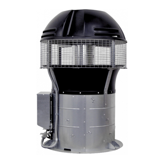
- Page 1 Installation and maintenance ENGLISH VBP+ R Hybrid assistance ventilation fan TF5774_C EN - Document not contractual. Aereco can realise technical modifications on its products without prior notice.
-
Page 2: Table Of Contents
STARTING UP / OPERATION ............................18 .................................. 18 MODE ................................. 19 MODE ............................19 NSTALLATION CHECK UP MAINTENANCE ................................20 ..............................20 RIOR WARNINGS ............................ 20 AINTENANCE AND CLEANING TECHNICAL ASSISTANCE ............................21 WARRANTY ..................................22 PROTECTION OF THE ENVIRONMENT ........................22 TF5774_C Aereco S.A. -
Page 3: Introduction
▪ The number of fans and their arrangement must be studied so as to ensure the proper operation of the system. ▪ In general, barring special cases, all ducts of a given stack of housing units must be equipped with one or more fans. TF5774_C Aereco S.A. -
Page 4: General
▪ Individual setting/adjustment of the speed of each fan according to the site configuration (number of storeys, ductwork...) ▪ Speed control of each fan according to the temperature, (item sold by Aereco), wind or by using a clock (items not sold by Aereco) ▪... -
Page 5: Product Data
5/22 PRODUCT DATA COMPONENTS Note: the MS mode also requires two specific modules, a temperature probe and other electrical components. These elements are described in the manual specific to this mode. DIMENSIONS Dimensions in mm. TF5774_C Aereco S.A. -
Page 6: Technical Data
6/22 TECHNICAL DATA Hybrid fan VBP+ R Version Code VB21184 VB21183 Aeraulics Maximum flowrate (Ref) Maximum pressure @ Maximum flowrate (Ref) Maximum pressure 39 Pa (@ 200 m³/h) 35 Pa (@ 200 m Electric Type of motor EC (Electronic Commutation) -
Page 7: Installation
The adaptation components must be made of a material strong enough to bear the weight of the fan(s). ▪ The latter must be fastened to the stack securely and so as to assure a good seal with it; the plenum as a ▪ whole must also be perfectly sealed. TF5774_C Aereco S.A. -
Page 8: Case Of An Individual Duct
Ø350 mm, that is to say 120 ▪ mm or 180 mm. The fan must be centred on the outlet section Ø350 mm. ▪ Example of a typical stack of the collective and individual type: TF5774_C Aereco S.A. -
Page 9: Case Of Ducts Grouped Under 2 Fans
It is forbidden to install more than 2 fans per stack. • The stacks (1 or 2 fans) must be at least 3 m apart (distance from the outer edge of the fan to the outer edge of the nearest fan of the other stack) TF5774_C Aereco S.A. -
Page 10: Anticipation Of Maintenance And Chimney Sweeping Constraints
Use only the 2 handles located under the uprights to handle the fan. ▪ Wear suitable gloves (some of the metal parts may be sharp) ▪ Do not set the fan down on an obstacle that might damage the turbine. ▪ Do not set the fan flat (horizontally) ▪ TF5774_C Aereco S.A. -
Page 11: Connections
The following drawings show the electrical connections according to the chosen working mode (ST or MS mode). Two cases can be identified: Case A = 230 V~ electrical box is far from the fans (for example in the stairs) ▪ ▪ Case B = 230 V~ electrical box is close to the fans in terrace TF5774_C Aereco S.A. - Page 12 ST mode: Case A: 230 V~ electrical box is far from the fans (for example in the stairs) ▪ ▪ Case B: 230 V~ electrical box is close to the fans in terrace TF5774_C Aereco S.A.
- Page 13 13/22 MS mode: ▪ Case A: 230 V~ electrical box is far from the fans (for example in the stairs) Case B: 230 V~ electrical box is close to the fans in terrace. ▪ TF5774_C Aereco S.A.
- Page 14 14/22 MS mode (recommendations) TF5774_C Aereco S.A.
-
Page 15: Power Connection
Add a grounding strap and connect it with the M6 screw , on the crimped nut provided for this purpose located on the fan casing 2 Reliée à la terre, cette tresse participe à la réduction des émissions CEM du produit et à limiter le danger dans le cas où le câble menant au moteur serait coupé (dispositif d'évacuation secondaire). TF5774_C Aereco S.A. -
Page 16: Configuring In St Or Ms Mode
Check that the power supply has in fact been cut off for at least 5 minutes before starting (to eliminate the risk of electrical shocks from the discharging of certain components). Remove the cover from the top of the fan. Remove the cover from the protection box of the user interface TF5774_C Aereco S.A. -
Page 17: Connection In St Mode
2, 3, 4. Connect the cable and mark each wire (using colours for example) in order to identify which wire is connected: 1, 2, 3, 4. MS cable edge Make the connection in accordance with standard practice via an IP65 junction box installed at the base of the fan. TF5774_C Aereco S.A. -
Page 18: Starting Up / Operation
Any curve between the minimum (a) and maximum (b) curves presented in the graph below can be obtained. The number of possible adjustments between these curves is infinite. Intermediary curves are given as examples (not exhaustive). Screw the plug back. Then put the top cover back on the fan. TF5774_C Aereco S.A. -
Page 19: Ms Mode
Wait 15 minutes (checking time) to ensure there are no error messages on the modules □ Check that the numbered modules are connected to the equivalent fans (Module 1 to fan 1, etc.) □ Check the group configuration (see module manual) TF5774_C Aereco S.A. -
Page 20: Maintenance
Cut the plastic clips that secure the access hatch to the fixed part of the fence. DO NOT CUT the metallic staple linking the access hatch to the support. Open to clean the inside of the fan. Close the access hatch and put some new plastic clips. TF5774_C Aereco S.A. -
Page 21: Technical Assistance
The coupling is damaged The fan makes anormal Check the coupling’s condition (visual control) noise In case actions mentionned above does not solve the issue, or for any other question, please contact your retailer. TF5774_C Aereco S.A. -
Page 22: Warranty
This appliance is guaranteed for two years, counting from the date of purchase, against any manufacturing defects. In this context, Aereco replaces the appliance or supplies the parts found to be defective after appraisal by its customer service department. In no case does the warranty cover other expenses, such as labour costs, travel, or indemnification of any kind.
Need help?
Do you have a question about the VBP+ R and is the answer not in the manual?
Questions and answers