Advertisement
Available languages
Available languages
Quick Links
Programmable Controllers
Installation Manual for digital Input and
Output Modules
Art. no.: 260563, ENG, Version B, 14012013
Safety Information
For qualified staff only
This manual is only intended for use by properly trained and qualified electri-
cal technicians who are fully acquainted with automation technology safety
standards. All work with the hardware described, including system design,
installation, setup, maintenance, service and testing, may only be performed
by trained electrical technicians with approved qualifications who are fully
acquainted with the applicable automation technology safety standards and
regulations.
Proper use of equipment
The programmable controllers (PLC) of the MELSEC L series are only intended
for the specific applications explicitly described in this manual or the manuals
listed below. Please take care to observe all the installation and operating
parameters specified in the manual. All products are designed, manufactured,
tested and documented in agreement with the safety regulations. Any modi-
fication of the hardware or software or disregarding of the safety warnings
given in this manual or printed on the product can cause injury to persons or
damage to equipment or other property. Only peripherals and expansion
equipment specifically recommended and approved by Mitsubishi Electric
may be used with the programmable controllers of the MELSEC L series. Any
other use or application of the products is deemed to be improper.
Relevant safety regulations
All safety and accident prevention regulations relevant to your specific appli-
cation must be observed in the system design, installation, setup, mainte-
nance, servicing and testing of these products.
In this manual special warnings that are important for the proper and safe use
of the products are clearly identified as follows:
DANGER:
P
Personnel health and injury warnings.
Failure to observe the precautions described here can result
in serious health and injury hazards.
E
CAUTION:
Equipment and property damage warnings.
Failure to observe the precautions described here can result
in serious damage to the equipment or other property.
Further information
The following manuals contain further information about the module:
● Instruction leaflet "Before Using the Product" for LX10, LX28, LX40C6, LX41C4,
LX42C4, LY10R2, LY20S6, LY40NT5P, LY41NT1P, LY42NT1P, LY40PT5P,
LY41PT1P and LY42PT1P
● MELSEC L series I/O Module User's Manual
● MELSEC L series CPU Module User's Manual
(Hardware Design, Maintenance and Inspection)
● MELSEC System Q/L series Programming Manual
● Safety Guidelines for MELSEC L series CPU
These manuals are available free of charge through the internet
(https://eu3a.mitsubishielectric.com).
If you have any questions concerning the installation, configuration or opera-
tion of the equipment described in this manual, please contact your relevant
sales office or department.
I/O Modules
Overview of the Modules
Input/output points
Module
I/O- Connection
Number
Type
LX10
16 Inputs
Terminal block
AC
LX28
8 Inputs
Terminal block
LX40C6
16 Inputs
Terminal block
DC
(positive/
LX41C4
32 Inputs
40-pin connector
negative
LX42C4
64 Inputs
common)
2x40-pin connector
Relay
LY10R2
16 Outputs
Terminal block
contact
LY20S6
16 Outputs
Triac
Terminal block
LY40NT5P
16 Outputs
Terminal block
Transistor
LY41NT1P
32 Outputs
40-pin connector
(sink)
LY42NT1P
64 Outputs
2x40-pin connector
LY40PT5P
16 Outputs
Terminal block
Transistor
LY41PT1P
32 Outputs
40-pin connector
(source)
LY42PT1P
64 Outputs
2x40-pin connector
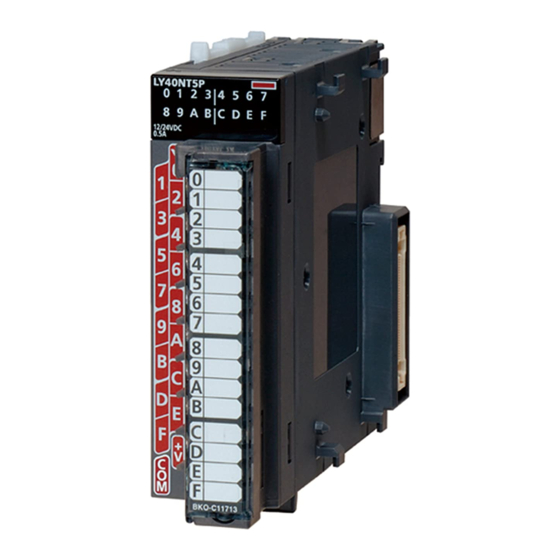
Part Names
18-point screw
40-pin
2x40-pin
terminal block type
connector type
connector type
³
·
³
·
³
·
»
¿
²
³
º
³
º
³
º
No. Description
³
Module joint lever (for connecting two modules)
Indicates the I/O status
·
I/O status LEDs
ON:
I/O signal is ON
OFF: I/O signal is OFF
Terminal block
18-point terminal block for connecting I/O
»
(removable)
signal cables to/from external devices
¿
Terminal cover
Used to switch the I/O status LED indication
Indication selector
´
between the first 32 points and the second
switch
32 points of a 64-point module.
I/O Connector(s)
Connector(s) for I/O signal cables to/from
²
(40 pins)
external devices.
Serial number plate
º
DIN rail mounting hook (at the backside of the module)
Operate the switch with your fingers. Do not use a screwdriver or similar tool as it
may damage the switch.
Pin arrangement of the terminal block
The terminal block is shown in module front view.
8-point type
16-point type
Pin arrangement of the connectors
The connectors are shown in module front view.
● 40-pin connector
B20
A20
B19
A19
B18
A18
B17
A17
B16
A16
´
B15
A15
²
B14
A14
B13
A13
B12
A12
B11
A11
B10
A10
B9
A9
B8
A8
B7
A7
B6
A6
B5
A5
B4
A4
B3
A3
B2
A2
B1
A1
● 2x40-pin connector
1B20
1A20
2B20
1B19
1A19
2B19
1B18
1A18
2B18
1B17
1A17
2B17
1B16
1A16
2B16
1B15
1A15
2B15
1B14
1A14
2B14
1B13
1A13
2B13
1B12
1A12
2B12
1B11
1A11
2B11
1B10
1A10
2B10
1B9
1A9
2B9
1B8
1A8
2B8
1B7
1A7
2B7
1B6
1A6
2B6
1B5
1A5
2B5
1B4
1A4
2B4
1B3
1A3
2B3
1B2
1A2
2B2
1B1
1A1
2B1
Dimensions
● Modules with terminal block
DIN rail centre
4
95
117
All dimensions are in "mm"
● Modules with connector(s)
DIN rail centre
4
95
All dimensions are in "mm"
Specifications
General specifications
Item
when operating
Ambient
temperature
when stored
Ambient humidity when operating
2A20
2A19
Working atmosphere
2A18
2A17
2A16
Installation location
2A15
2A14
Further general specifications can be found in the Safety Guidelines for
2A13
MELSEC L series CPU.
2A12
2A11
2A10
2A9
2A8
2A7
2A6
2A5
2A4
2A3
2A2
2A1
28.5
28.5
Specifications
0 to 55 °C
–25 to 75 °C
5 to 95 % RH (no condensation)
Free from corrosive or flammable gas
and excessive conductive dusts
Inside control panel
Advertisement

Related Manuals for Mitsubishi Electric MELSEC L Seies


Summary of Contents for Mitsubishi Electric MELSEC L Seies
- Page 1 Only peripherals and expansion equipment specifically recommended and approved by Mitsubishi Electric ´ »...
- Page 2 Installation and Wiring AC input modules Relay output module Transistor output modules – Sink type Specifications LX10 LX28 Specifications LY10R2 Specifications LY40NT5P LY41NT1P LY42NT1P DANGER Number of inputs Number of outputs Number of outputs Turn off all phases of the power supply for the PLC and other external Insulation method Photocoupler Output type...
- Page 3 Mounting the modules on a DIN rail Modules with 40-pin connector(s) Wiring of the output modules Modules with 40-pin connector ● LX41C4 Modules with terminal block Pull down DIN rail hooks on ● LY10R2 – Relay type The following connectors are applicable for the I/O modules. Connection diagram Signal Signal...
- Page 4 2A01, 2A02 1A01, 1A02 2A01, 2A02 Load 12/24 V DC 12 V DC/24 V DC B01, B02 A01, A02 Vacant Vacant Mitsubishi Electric Europe B.V. /// FA - European Business Group /// Germany /// Tel.: +49(0)2102-4860 /// Fax: +49(0)2102-4861120 /// https://eu3a.mitsubishielectric.com...
- Page 5 E/A-Module Übersicht der Module Pin-Belegung des Klemmenblocks Abmessungen Programmierbare Steuerungen ● Module mit Klemmenblock Der Klemmenblock ist mit Blick auf das Modul dargestellt. Eingänge/Ausgänge Modul E/A-Anschluss 8-polig 16-polig Anzahl LX10 16 Eingänge Klemmenblock LX28 8 Eingänge Klemmenblock Mitte der DIN-Schiene LX40C6 16 Eingänge Klemmenblock...
- Page 6 Installation und Verdrahtung AC-Eingangsmodule Relais-Ausgangsmodul Transistor-Ausgangsmodule – minusschaltend Technische Daten LX10 LX28 Technische Daten LY10R2 Technische Daten LY40NT5P LY41NT1P LY42NT1P GEFAHR Anzahl der Eingänge Anzahl der Ausgänge Anzahl der Ausgänge Schalten Sie vor der Installation und der Verdrahtung die Versorgungs- Isolation Optokoppler Ausgangstyp...
- Page 7 Montage der Module auf einer DIN-Schiene Module mit 40-poliger Anschlussbuchse Anschluss der Ausgangsmodule Module mit 40-poligem Steckanschluss ● LX41C4 Die folgenden Stecker sind für die E/A-Module geeignet. Ziehen Sie die Laschen zur Module mit Schraubklemmen Anschlussbelegung Signal Signal DIN-Schienen-Montage an ●...
- Page 8 1A01, 1A02 2A01, 2A02 Last 12/24 V DC 12 V DC/24 V DC B01, B02 A01, A02 Nicht Nicht belegt belegt Mitsubishi Electric Europe B.V. /// FA - European Business Group /// Germany /// Tel.: +49(0)2102-4860 /// Fax: +49(0)2102-4861120 /// https://de3a.mitsubishielectric.com...
- Page 9 ´ » Seuls les périphériques et équipements complémentaires spécifiquement recommandés par Mitsubishi Electric peuvent être utilisés avec les automates ¿ ² ² programmables industriels de la série MELSEC L. Tout autre emploi ou applica- tion des produits sera considéré...
- Page 10 Installation et câblage Modules d'entrée CA Module avec sortie relais Modules de sortie à transistor – commutation négative Données techniques LX10 LX28 Données techniques LY10R2 Données techniques LY40NT5P LY41NT1P LY42NT1P DANGER Nombre d'entrées Nombre de sorties Nombre de sorties Toujours couper la tension d'alimentation de l'API et les autres tensions Isolation Photocoupleur Type de sortie...
- Page 11 Montage des modules sur un profilé DIN Modules avec connecteur(s) 40 broches Raccordement des modules de sortie Modules avec prise embrochable de 40 broches ● LX41C4 Les connecteurs suivants sont utilisables avec les modules d’entrées/sorties. Faites glisser les crochets du Modules avec bloc de jonction Affectation des broches Broche...
- Page 12 2A01, 2A02 1A01, 1A02 2A01, 2A02 Charge 12/24 V CC 12 V CC/24 V CC B01, B02 A01, A02 affecté affecté Mitsubishi Electric Europe B.V. /// FA - European Business Group /// Germany /// Tel.: +49(0)2102-4860 /// Fax: +49(0)2102-4861120 /// https://eu3a.mitsubishielectric.com...
- Page 13 ¿ ² ² sono essere utilizzate esclusivamente periferiche o apparecchiature di espan- sione specificamente approvate da Mitsubishi Electric. Ogni altro utilizzo o applicazione che vada oltre quanto illustrato è da considerarsi non conforme. Norme rilevanti per la sicurezza 28,5 Nella progettazione, installazione, messa in funzione, manutenzione e col-...
- Page 14 Installazione e cablaggio Moduli d'ingresso AC Moduli di uscita a relè Moduli di uscita a transistor – Tipo sink Specifiche tecniche LX10 LX28 Specifiche tecniche LY10R2 Specifiche tecniche LY40NT5P LY41NT1P LY42NT1P PERICOLO Numero degli ingressi Numero di uscite Numero di uscite Prima di effettuare l'installazione e l'allacciamento, disinserire la ten- Isolamento Optoisolatore...
- Page 15 Montaggio dei moduli su guida DIN Moduli con connettore a 40 poli Moduli con connettore a 40 poli Collegamento dei moduli d'uscita ● LX41C4 Modulo con morsettiera Tirare verso il basso i ganci ● LY10R2 – Uscita a relé Sui moduli di I/O possono essere usati i seguenti connettori. Schemi di connessione Segnale Segnale...
- Page 16 12/24 V DC 1A01, 1A02 2A01, 2A02 1A01, 1A02 2A01, 2A02 A01, A02 12 V DC/24 V DC occu- occu- pato pato Mitsubishi Electric Europe B.V. /// FA - European Business Group /// Germany /// Tel.: +49(0)2102-4860 /// Fax: +49(0)2102-4861120 /// https://eu3a.mitsubishielectric.com...
-
Page 17: Especificaciones
L de MELSEC sólo se permite el empleo de los disposi- ¿ ² ² tivos adicionales o de ampliación recomendados por MITSUBISHI ELECTRIC. Todo empleo o aplicación distinto o más amplio del indicado se considerará como no reglamentario. Normas relevantes para la seguridad 28,5 Al realizar trabajos de proyección, instalación, puesta en funcionamiento, mante-... - Page 18 Instalación y cableado Módulos de salida de relé Módulos de entrada AC Módulos de salida a transitor Especificaciones LY10R2 Especificaciones LY40NT5P LY41NT1P LY42NT1P Especificaciones LX10 LX28 PELIGRO Número de salidas Número de salidas Número de entradas Tipo de salida Transistor (NPN) Antes de empezar con la instalación y con el cableado, hay que desconec- Tipo de salida Relé...
- Page 19 Montaje de los módulos en un carril DIN Módulos con hembrilla de conexión de 40 polos Módulos con conector de 40 polos Conexión de los módulos de salida ● LX41C4 Módulo con bornes de tornillo Empuje hacia abajo hasta ● LY10R2 – Contacto de relé Los siguientes conectores son apropiados para módulos E/S.
- Page 20 2A01, 2A02 1A01, 1A02 2A01, 2A02 Carga 12/24 V DC 12 V DC/24 V DC B01, B02 A01, A02 asignar asignar Mitsubishi Electric Europe B.V. /// FA - European Business Group /// Germany /// Tel.: +49(0)2102-4860 /// Fax: +49(0)2102-4861120 /// https://eu3a.mitsubishielectric.com...
- Page 21 щихся в этом руководстве или указанных на продукции, могут привести к серь- езным травмам и/или материальному ущербу. В сочетании с программируемыми контроллерами серии L разрешается использовать модули расширения ´ и аксессуары, рекомендуемые фирмой Mitsubishi Electric. Использование » любых иных устройств считается использованием не по назначению. ¿...
- Page 22 Установка и выполнение электропроводки Модули релейных выходов Модули входа переменного тока Модули транзисторных выходов – с отрицательной логикой Технические данные LY10R2 Технические данные LY40NT5P LY41NT1P LY42NT1P Технические данные LX10 LX28 ОПАСНОСТЬ Кол-во выходов Кол-во выходов Кол-во выходов Транзисторный Тип выхода Тип...
- Page 23 Монтаж модуля на DIN-рейке Модули с 40-контактными разъёмами Модули с 40-контактным разъёмом Подключение модулей выхода ● LX41C4 Модуль с клеммной колодкой Оттяните монтажные серьги ● LY10R2 – релейного типа Для модулей входов/выходов применяются следующие разъёмы. Схема подключения Контакт Сигнал Контакт Сигнал...
- Page 24 1A01, 1A02 2A01, 2A02 A01, A02 12 В пост. т./24 В пост. т. Не Не исполь- исполь- зуется зуется 0 В Mitsubishi Electric Europe B.V. /// FA - European Business Group /// Germany /// Tel.: +49(0)2102-4860 /// Fax: +49(0)2102-4861120 /// https://eu3a.mitsubishielectric.com...
- Page 25 Tylko urządzenia peryferyjne i sprzęt rozszerzający, szczegółowo zalecone i dopuszczone przez ¿ ² ² Mitsubishi Electric, mogą być używane wraz ze sterownikami programowalnymi serii MELSEC L. Wszystkie inne zastosowania będą uważane za niewłaściwe. 28.5 Regulacje związane z bezpieczeństwem Jednostka: mm Wszystkie regulacje bezpieczeństwa zapobiegające wypadkom i właściwe dla...
- Page 26 Moduły z wyjściami przekaźnikowymi Instalacja i okablowanie Moduły z wejściami AC Moduły z wyjściami tranzystorowymi – typ sink Wymagania LY10R2 Wymagania LX10 LX28 Wymagania LY40NT5P LY41NT1P LY42NT1P NIEBEZPIECZEŃSTWO Liczba wyjść Liczba wejść Liczba wyjść Rodzaj wyjścia Przekaźnik Przed rozpoczęciem instalacji okablowania należy odłączyć wszystkie Metoda izolacji Złącze optoelektroniczne Rodzaj wyjścia...
- Page 27 Montaż modułów na szynie DIN Moduły z 40-stykowymi złączami Moduły z 40-stykowymi złączami Okablowanie modułów wyjściowych ● LX41C4 Moduł z listwą zaciskową Umieszczony pod modułem ● LY10R2 – typ przekaźnikowy Poniższe złącza są stosowane do modułów we/wy Złącze Styk Sygnał Styk Sygnał...
- Page 28 2A01, 2A02 1A01, 1A02 2A01, 2A02 Obciążenie 12/24 V DC 12 V DC/24 V DC B01, B02 A01, A02 Wolny Wolny Mitsubishi Electric Europe B.V. /// FA - European Business Group /// Germany /// Tel.: +49(0)2102-4860 /// Fax: +49(0)2102-4861120 /// https://eu3a.mitsubishielectric.com...
- Page 29 és egyéb tulajdon károsodását okozhatja. A MELSEC L sorozathoz tartozó programozható logikai vezérlők együttes használata egyéb berendezésekkel kifejezetten csak a Mitsubishi Electric által jóváha- gyott tartozékokkal és perifériákkal megengedett. A termékek bármely más ´...
- Page 30 Felszerelés és huzalozás Relé kimeneti modulok AC bemeneti modulok Tranzisztoros kimeneti modulok – Negatív kapcsolású Előírás LY10R2 Előírás LY40NT5P LY41NT1P LY42NT1P Előírás LX10 LX28 VESZÉLY Kimenetek száma Bemenetek száma Bemenetek száma Kimenet típusa Tranzisztor (negatív kapcsolású) Kimenet típusa Relé A felszerelési és huzalozási munkálatok megkezdése előtt mindig kap- Szigetelés Optocsatoló...
- Page 31 Modulok felszerelése DIN sínre Modulok 40 tűs csatlakozóval 40-tűs csatlakozós modulok Kimeneti modulok bekötése ● LX41C4 Sorkapcsos modulok Húzza le a modulok hátolda- ● LY10R2 – Relés típus Az I/O modulok esetében a következő csatlakozók használhatók. Kapcsolási rajz Tű Tű lán található...
- Page 32 12/24 V DC B01, B02 1A01, 1A02 2A01, 2A02 1A01, 1A02 2A01, 2A02 A01, A02 12 V DC/24 V DC Mitsubishi Electric Europe B.V. /// FA - European Business Group /// Germany /// Tel.: +49(0)2102-4860 /// Fax: +49(0)2102-4861120 /// https://eu3a.mitsubishielectric.com...
- Page 33 Smějí se používat pouze příslušenství a periférie specificky ´ schválené společností MITSUBISHI ELECTRIC. Jakékoli jiné aplikace produktu » budou považovány za nesprávné. ¿...
- Page 34 Vstupní moduly AC Reléové výstupní moduly Instalace a kabelové propojení Tranzistorové výstupní moduly – Spínající mínus Technické údaje LX10 LX28 Technické údaje LY10R2 Technické údaje LY40NT5P LY41NT1P LY42NT1P NEBEZPEČÍ Počet vstupů Počet výstupů Počet výstupů Typ výstupu Tranzistor (spínající záporný pól) Galvanické...
- Page 35 Montáž modulů na DIN lištu Moduly se 40pólovým konektorem Moduly s 40pólovým konektorovým připojením Připojení výstupních modulů ● LX41C4 Pro I/O moduly jsou vhodné následující konektory. Modul se šroubovými svorkami Přitlačte montážní závěsy pro ● LY10R2 – Reléový kontakt Zapojení svorek Signál Signál montáž...
- Page 36 2A01, 2A02 1A01, 1A02 2A01, 2A02 Zátěž 12/24 V DC B01, B02 12 V DC/24 V DC A01, A02 Nevyužit Nevyužit Mitsubishi Electric Europe B.V. /// FA - European Business Group /// Germany /// Tel.: +49(0)2102-4860 /// Fax: +49(0)2102-4861120 /// https://eu3a.mitsubishielectric.com...
Need help?
Do you have a question about the MELSEC L Seies and is the answer not in the manual?
Questions and answers