
Subscribe to Our Youtube Channel
Related Manuals for technetix AIMA-FPAS


Summary of Contents for technetix AIMA-FPAS
- Page 1 AIMA-FPAS RF FORWARD PATH AMPLIFIER- STANDARD Product user manual Online Email: customer.service.vdl@technetix.com Website: technetix.com Technetix Group Limited 2018-08/EN V2...
-
Page 2: Table Of Contents
5.3 Module installation ....................................10 5.4 Check module LEDs ....................................11 5.5 Test the RF input signal....................................11 Module configuration & alarm setup ........................12 6.1 Port configuration screen ..................................12 6.2 Alarms monitoring .....................................14 6.2.1 Alarm status pages ..................................14 2018-08/EN V2 Technetix Group Limited... - Page 3 6.2.5 Input/Output status monitoring ...............................18 6.3 Logs management .....................................19 6.4 Device upgrade......................................20 6.5 Restoring factory defaults ..................................21 6.6 Reboot ...........................................23 Troubleshooting .................................24 Appendix A: Default alarm limit settings ........................25 Appendix B: Factory default settings ..........................25 2018-08/EN V2 Technetix Group Limited...
-
Page 4: About This Manual
Before you use the manual, please familiarise yourself with the format used in this manual. ‘*’Asterisk: Points marked with an asterisk means there is a corresponding note on the page. 1.4 Technical Support If you need help in the process of setting up and maintaining an FPAS, please contact Technetix's technical support staff: Europe:... -
Page 5: Precautions
Outage or overload requiring service and repairs Unplug the unit and refer the servicing to qualified service personnel only. Servicing and repairs DO NOT attempt to service this unit yourself. Refer all servicing needs to qualified service personnel only. 2018-08/EN V2 Technetix Group Limited... -
Page 6: Overview
Remote firmware upgrade and auto upload/download of configuration files through the ASMM web interface or using the NMSE ■ Bulk firmware updates through the NMSE ■ FCC, CE and RCM compliant See Declaration of Conformity for current status. 2018-08/EN V2 Technetix Group Limited... -
Page 7: Specifications
90% (Non-condensing) Storage temperature -25 - 70°C Storage humidity 90% (non-condensing) Dimensions (W*D*H) 24.6 * 410 * 152.5 mm Weight Single: 0.88 kg Dual: 0.98 kg Supported network management options NMSE or through ASMM’s Web interface 2018-08/EN V2 Technetix Group Limited... -
Page 8: Block Diagram
RF input Attenuator TP RF IN -20 dB RF -20 dB input test point SLOPE Slope control RF OUTPUT RF output TP RF OUT -20 dB RF -20 dB output test point Input gain Input gain 2018-08/EN V2 Technetix Group Limited... -
Page 9: Order Details
Output Gain Output gain TO BACK PLANE AND COMMS Data bus Central processing unit 3.4 Order details A-FPAS-[Y]-[Z] Forward-Path Amplifier - Standard Options: Ports Single Dual Bandwidth 45 - 1000 MHz (Standard) 45 - 1218 MHz 2018-08/EN V2 Technetix Group Limited... -
Page 10: Module Characteristics
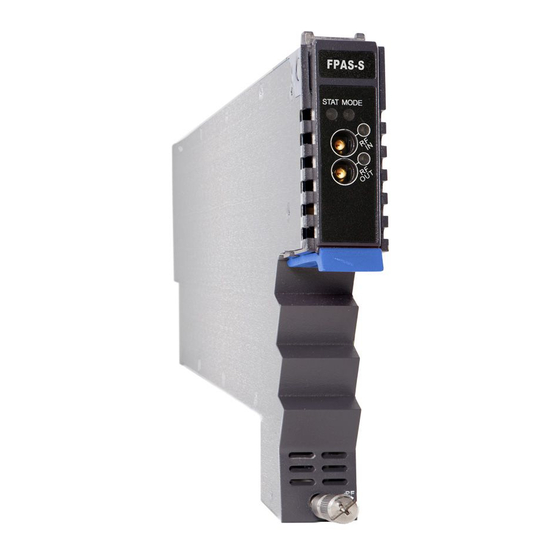
AIMA-FPAS Product User Manual Product user manual AIMA-FPAS 4 Module Characteristics 4 Module characteristics 4.1 Module Appearance and Port Layout 4.1 Module appearance and port layout 4.1.1 Overview 4.1.1 Overview Front Panel Rear Panel Figure 4-1 module appearance Figure 4-1 Module Appearance... -
Page 11: Fpas-S Front Panel Layout
Major alarm: Red RF OUT TP RF output test point Used to plug and anchor the module Orange tab-retaining clip The tab-retaining clip will pop-up after pressing the release and plug module. Mounting Screw Module fastening screw 2018-08/EN V2 Technetix Group Limited... -
Page 12: Fpas-S Rear Panel Layout
RF IN RF input RF OUT RF output Air vent Air vent allowing air to flow out of the module Multi-pin connector Power and communication port Placement pin Used to position the module in the chassis 2018-08/EN V2 Technetix Group Limited... - Page 13 The retaining clip tab will pop-up after Normal: Green clip tab RF1 OUT LED pressing the release and plug module. Minor alarm: Amber Major alarm: Red Mounting RF IN TP RF1 input test point Module fastening screw screw 2018-08/EN V2 Technetix Group Limited...
- Page 14 RF2 IN RF2 input RF2 OUT RF2 output Air vent Air vent allowing air to flow out of the module Multi-pin connector Power and communication port Placement pin Used to position the module in the chassis 2018-08/EN V2 Technetix Group Limited...
-
Page 15: Installation
Before installing this device, you must ensure that the unit is intact and ready for installation. Unpack and check the unit: Open the box to check for any damage that may have occurred during shipment. If damage is found, please contact a Technetix customer support representative. Necessary equipment and tools for installation:... -
Page 16: Module Installation
Product user manual AIMA-FPAS Product User Manual AIMA-FPAS 5.3 Module Installation 5.3 Module installation Gently depress the orange retaining clip and release the hinged tab 1. Gently depress the orange retaining clip and release the hinged tab Hinged tab Hinged tab... -
Page 17: Check Module Leds
The BC/NC status indicators show a green light. 5.5 Test the RF input signal When setting up the transmitter for final deployment, the RF input levels must not exceed 20 dB. 2018-08/EN V2 Technetix Group Limited... -
Page 18: Module Configuration & Alarm Setup
6.1 Port configuration screen After logging in to the AIMA ASMM controller, select the 'Modules' tab and then the 'FPAS' to configure one of the FPAS modules. After selecting the 'FPAS', the 'Port' option will appear. 2018-08/EN V2 Technetix Group Limited... - Page 19 'Alarm Settings' become available. Total Gain is calculated by adding the Input Gain Level and the Output Gain Level with 10 dB. AGC Range is from (10- 'Input Gain Control') to (0- 'Input Gain Control') 2018-08/EN V2 Technetix Group Limited...
-
Page 20: Alarms Monitoring
Click the 'Alarms' tab on the top menu bar to display an overview of the alarm status of all the installed modules. The module row has an alarm status indicator used to show: Normal operation: Green Major alarm: Red 2018-08/EN V2 Technetix Group Limited... -
Page 21: Module Operating Voltage And Temperature Alarm
The status has three conditions: Normal: Green Major alarm: Red Use the status indicators to determine if the module is working properly. If the device is replaced or reset, click on 'Refresh' to update the alarm information. 2018-08/EN V2 Technetix Group Limited... -
Page 22: Module Port Alarms
Click on the 'Port' label under the selected module on the left column. On the module 'Port' page, the operator can view the 'Input Power', 'Output Power', and the 'AGC Status' alarms: The status has three conditions: Normal: Green Major alarm: Red 2018-08/EN V2 Technetix Group Limited... -
Page 23: Alarm Monitoring Configuration
When the check box is checked (detection ON), the text in the text box will be solid black. When a check box is NOT checked, (detection OFF), the text in the text box will be light grey and cannot be changed. 2018-08/EN V2 Technetix Group Limited... - Page 24 Product user manual AIMA-FPAS Table 6-1 Threshold Default Alarm Parameter HIHI LOLO Deadband changeable Enable Temperature 70.0 65.0 -5.0 (oC) +12V Input 13.5 10.5 Voltage (V) +5V Input Voltage (V) 2018-08/EN V2 Technetix Group Limited...
-
Page 25: Input/Output Status Monitoring
To setup Input/Output status monitoring, select the 'Port' label from the left menu under the desired module, and then the monitoring parameters will be listed the in the 'Alarm Settings' section, click on ✓ to toggle the alarms. Customers can change the monitoring parameters. 2018-08/EN V2 Technetix Group Limited... -
Page 26: Logs Management
Mode Control sec), AGC Green always 6.3 Logs management The operator can view all the alarms of the modules in the chassis on the logs management page. Click 'Logs' to enter the logs management page. 2018-08/EN V2 Technetix Group Limited... -
Page 27: Device Upgrade
Module will be upgraded after the firmware is uploaded. The upgrading and reboot process will take about 30 seconds. During the upgrading, please don’t power off the device and don’t plug any module in the same chassis, or it may lead to upgrade fail or data sync error. 2018-08/EN V2 Technetix Group Limited... -
Page 28: Restoring Factory Defaults
'Factory Defaults' section. When finished, the device configuration will be reset. For more detailed factory reset information, please refer to the factory restore and upgrade configuration parameters table as in Table 6-4. Note: All the powers displayed on the webpage are total power. 2018-08/EN V2 Technetix Group Limited... - Page 29 Table 6-4 Factory default and upgrade configuration parameters table Parameters Configuration Factory default value Alarm Control Enable/Disable Enable Gain Control Type AGC/MGC Slope Control (dB) (0.0-9.0) Input Gain Control (dB) (0.0-10.0) Output Gain Control (dB) (0.0-10.0) AGC Status Alarm enableMajor/enableMinor/disable enableMajor 2018-08/EN V2 Technetix Group Limited...
-
Page 30: Reboot
'Reboot' section. Next, click on 'Submit' to confirm, and then the module will automatically restart. The configuration of the module will not be lost after rebooting. 1 Click the module to be configured 2 Click 'Apply' to reboot device 2018-08/EN V2 Technetix Group Limited... -
Page 31: Troubleshooting
Check the fans, or lower the room temperature. Operating environment temperature is lower or higher If the temperature is normal, please contact Technetix’s technical support. Please contact Technetix’s +12V/+5V Input voltage is lower or higher. STAT is amber technical support. -
Page 32: Appendix A: Default Alarm Limit Settings
Appendix B: Factory default settings Parameters Conditions Factory default value Alarm detection control ON/OFF Output control ON/OFF Output gain type MGC/AGC Input gain control (dB) 0 - 10 Output gain control (dB) 0 - 10 Remote node control ON/OFF 2018-08/EN V2 Technetix Group Limited...
Need help?
Do you have a question about the AIMA-FPAS and is the answer not in the manual?
Questions and answers