
Related Manuals for technetix AIMA3000.EDFA


Summary of Contents for technetix AIMA3000.EDFA
- Page 1 AIMA3000.EDFA Erbium Doped Fibre Amplifier Product User Manual May/2016 - Version 1.0...
- Page 2 AIMA3000.EDFA Product User Manual AIMA3000.EDFA Erbium Doped Fibre Amplifier Product User Manual Technetix Group Limited May/2016 - Version 1.0 sales@technetix.com • technetix.com...
-
Page 3: Table Of Contents
5.4.4 Connecting the Optical Fibres ..............................25 5.5 Check Module LEDs ....................................25 5.6 Test the Optical Input Signal ................................25 5.7 Test the Optical Output Signal ................................25 Module Configuration & Alarms ..........................27 Technetix Group Limited May/2016 - Version 1.0 sales@technetix.com • technetix.com... - Page 4 AIMA3000.EDFA Product User Manual Port Configuration screen ..................................27 6.2 Reboot ........................................31 6.3 Alarms Monitoring ....................................32 6.3.1 Alarm Status Pages ..................................32 6.3.2 Module operating voltage and temperature alarm ......................33 6.3.3 Module Port Alarms..................................34 6.3.4 Alarm Settings Configuration ..............................35 6.3.5 Input/ Output Status Monitoring ...............................36 6.3.6 Default Port Page Alarm Thresholds (EDFA-1-17-G) ......................37...
-
Page 5: About This Manual
AIMA3000.EDFA Product User Manual 1 About This Manual 1.1 Related Documentation The following documents may be used in conjunction with this manual: • AIMA.3000 - Product User Manual • AIMA ASMM - Product User Manual • AIMA3000 NMS Web Management System Product User Manual Technetix.NMS3-EPSM - Basic Inventory Management... -
Page 6: Technical Support
AIMA3000.EDFA Product User Manual 1.2 Technical Support If you need help in the process of setting up and maintaining EDFA, please contact Technetix technical support staff: Europe: Technetix BV Kazemat 5 NL-3905 NR Veenendaal P.O. Box 385 NL-3900 AJ Veenendaal... -
Page 7: Precautions
Outage or overload requiring service and repairs Unplug the unit and refer the servicing to Technetix qualified service personnel only. Servicing and repairs DO NOT attempt to service this unit yourself. Refer all servicing needs to Technetix qualified service personnel only. WARNING! Exposure to class 3A laser radiation is possible. -
Page 8: Overview
3 Overview 3.1 Product Description The Erbium Doped Fibre Amplifier (EDFA) is designed to plug into Technetix latest generation Advanced Intelligent Multi- services Access platform - the AIMA3000. Technetix AIMA3000 EDFA module works in conjunction with 1550 nm optical transmitter modules to meet client requirements for different environments and transmission distances. -
Page 9: Specifications
(1) The recommended input power for an A-EDFA-1-17-G-S with 11 dBm optical input with a 6 dB gain typically has an output of 17 dB (2) Standard option. Contact a Technetix Sales Representative for availability of other options. Technetix Group Limited May/2016 - Version 1.0... -
Page 10: Block Diagram
AIMA3000.EDFA Product User Manual 3.4 Block Diagram Figure 3-1 EDFA Block Diagram Table 3-1 EDFA Block Diagram Glossary Parameters Glossary OPTICAL INPUT OPTICAL INPUT ISOLATOR ISOLATOR Wavelength Division Multiplexer ERBIUM DOPED FIBRE ERBIUM DOPED FIBRE PUMP LASER PUMP LASER INPUT SENSOR... -
Page 11: Order Details
Working mode Constant Power Constant Gain Optical Connector Type SC/APC E2000/APC FC/APC LC/APC Notes: (1) LC/APC connector only. (2) Standard option. Contact a Technetix Sales Representative for availability of other options. Technetix Group Limited May/2016 - Version 1.0 sales@technetix.com • technetix.com... - Page 12 AIMA3000.EDFA Product User Manual Product Code Examples Description A-EDFA-1-20-P-S AIMA3000 1-Slot EDFA Module with 1 output port, 20 dBm each, Constant Power, SC/APC connector A-EDFA-2-21-G-E AIMA3000 1-Slot EDFA Module with 2 output port, 21 dBm each, Constant Gain, E2000/APC connector...
-
Page 13: Module Characteristics
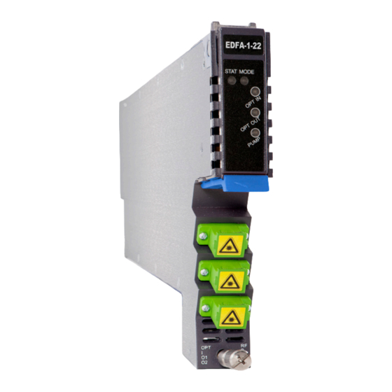
AIMA3000.EDFA Product User Manual 4 Module Characteristics 4.1 Module Appearance and Port Layout 4.1.1 Overview Rear Panel Front Panel Figure 4-1 Module Appearance Technetix Group Limited May/2016 - Version 1.0 sales@technetix.com • technetix.com... -
Page 14: Front Panel Layout
AIMA3000.EDFA Product User Manual 4.1.2 Front Panel Layout Figure 4-2 EDFA Front Panel Layout Technetix Group Limited May/2016 - Version 1.0 sales@technetix.com • technetix.com... - Page 15 AIMA3000.EDFA Product User Manual Table 4-1 EDFA Front Panel Functions Item Number Item Description Module power indicator MODE LED Normal: Green Module status indicator Normal: Green STAT LED Minor Alarm: Amber Major Alarm: Red Optical Input mode indicator Normal: Green...
-
Page 16: Rear Panel Layout
AIMA3000.EDFA Product User Manual 4.1.3 Rear Panel Layout Figure 4-3 Rear Panel Layout Table 4-2 EDFA Rear Panel Functions Item Number Item Description Air vent Air vent allowing air to flow out of the module Multi-pin connector Power and communication port... -
Page 17: Installation
Before installing this device, you must ensure that the unit is intact and ready for installation. Unpack and check the unit: Open the box to check for any damage that may have occurred during shipment. If damage is found, please contact a Technetix customer support representative. Necessary equipment and tools for installation:... -
Page 18: Module Installation
AIMA3000.EDFA Product User Manual 5.3 Module Installation Gently depress the orange retaining clip and release the hinged tab Hinged tab AIMA Module Orange retaining clip Hold the AIMA module casing upright, align it with the AIMA3000 slide rails for the correct slot, and insert the module until it reaches the multi-pin connector. -
Page 19: Connect The Optical Cabling
AIMA3000.EDFA Product User Manual After the module is inserted, gently push the hinged tab until it snaps into the orange retaining clip. While pushing down on the hinged tab, the AIMA module will mate with the power bus and will lock in into the chassis. - Page 20 AIMA3000.EDFA Product User Manual Then, pull the panel forward. Then lift up the handle and slide the fibre guide out of the front of the chassis. Technetix Group Limited May/2016 - Version 1.0 sales@technetix.com • technetix.com...
- Page 21 AIMA3000.EDFA Product User Manual DO NOT remove the dust cap from the fibre connector until right before connecting it to the input port. Raise the clip, insert the fibre connector, and then lower the clip over the connector. When using the sliding guide, put the fibre connector in the clip and slide it in from the rear to the front, through the chassis.
-
Page 22: Using The Fibre Tray
AIMA3000.EDFA Product User Manual 5.4.2 Using the Fibre Tray All optical fibres must be organised in a tidy manner in the chassis’s fibre tray, which provides enough space for up to 64 optical fibres. This allows for easy positioning and future replacement of optical fibres. Along the front of the chassis, there are cut-outs for keeping the optical fibres in position. - Page 23 AIMA3000.EDFA Product User Manual Use the Fibre Guide Tool to organise the cables and wires in the fibre tray to prevent tangles and the blocking of the guide rails. Fibre Tray Area Cut-outs Technetix Group Limited May/2016 - Version 1.0 sales@technetix.com...
-
Page 24: Cleaning The Fibre Connector Ends And Front-Panel Optical Ports
AIMA3000.EDFA Product User Manual 5.4.3 Cleaning the Fibre Connector Ends and Front-panel Optical Ports To obtain a good quality optical input signal, optical fibre input ports and fibre connector ends must be carefully cleaned. Connection terminal Head face When cleaning the optical fibre-connector end, remove the dust cap and then use a lint-free cloth dampened with a static dissipative solvent to clean the angled surface. -
Page 25: Connecting The Optical Fibres
AIMA3000.EDFA Product User Manual 5.4.4 Connecting the Optical Fibres Carefully lift up the hinged cover of the optical input port, align the raised tab on the connector with the slot in the port. Insert the connector until the connector is securely held in place indicated by a clicking sound. - Page 26 AIMA3000.EDFA Product User Manual 5.7 Test the Optical Output Signal Connect the optical input to the EDFA using a clean optical fibre cord. Connect the optical power metre to the optical amplifier output port by using the optical fibre cord. Ensure the difference of the power metre's reading and the module’s certificate of performance is not more than ±0.5 dBm.
-
Page 27: Module Configuration & Alarms
6 Module Configuration & Alarms The module’s configuration settings can be managed by using a web browser and NMS. This manual only provides the information regarding the ASMM’s web interface. For NMS configuration methods please refer to Technetix NMSE manual. 6.1 Port Configuration screen After logging in to the AIMA ASMM controller, select the “Modules”... - Page 28 AIMA3000.EDFA Product User Manual When selecting “Port” from the left column, it will open up the web GUI to configure the operation of the EDFA. Alarm Settings Factory Default Setting (bold) and range if applicable Enable Major Output Status Alarm...
- Page 29 AIMA3000.EDFA Product User Manual Table 6-2 for A-EDFA-x-x-G-x Description Items Sub Items Effect and Configuration Method Configuration Slot Module Information Module Type Green indicates output status red Output Status indicates no output Status Laser Type Unit Control Control Unit Switch...
- Page 30 AIMA3000.EDFA Product User Manual Detailed operations: Click “Modules” tab and click the module to be configured as shown in Figure 6-2. Click the “Apply” button under “Factory Defaults”. When finished, the device configuration will be reset. For more detailed information, refer to the factory restore and upgrade configuration parameter table shown in Table 6-3.
-
Page 31: Reboot
AIMA3000.EDFA Product User Manual 6.2 Reboot The module can be rebooted remotely, see Figure 6-4. Detailed operations: Click the “Modules” tab, select the “EDFA”, and then click the “Apply” button next to “Reboot”. Next, click on “Submit” to confirm, and then the module will automatically restart. The configuration of the module will be retained after rebooting. -
Page 32: Alarms Monitoring
AIMA3000.EDFA Product User Manual 6.3 Alarms Monitoring All the module alarms are shown on the alarm page. If an alarm occurs, the operator can view the associated pages to find more detailed alarm information. 6.3.1 Alarm Status Pages Click the “Alarms” tab on the top menu bar to display an overview of the alarm status for all the installed modules as shown in Figure 6-5. -
Page 33: Module Operating Voltage And Temperature Alarm
AIMA3000.EDFA Product User Manual 6.3.2 Module operating voltage and temperature alarm Click on the corresponding module, as shown in Figure 6-6, to view the module alarm information. After clicking on EDFA in "Modules" tab, the operator can view the module temperature and power supply voltage alarms. The operator can view the status indicators to check if the module is functioning properly. -
Page 34: Module Port Alarms
AIMA3000.EDFA Product User Manual 6.3.3 Module Port Alarms Click on the Module’s “Port” label on the left column, as shown in Figure 6-7. The Input, Output, laser output Total Power, Laser Bias current, Laser TEC current can be viewed from this page. -
Page 35: Alarm Settings Configuration
AIMA3000.EDFA Product User Manual 6.3.4 Alarm Settings Configuration Monitoring Function ON / OFF In the Configuration section on the Modules page, click the “Alarm Control” pull down menu to toggle the monitoring function. Temperature, +12V, +5V Voltage Alarm Levels Management By default, the temperature and voltage alarms are enabled. -
Page 36: Input/ Output Status Monitoring
AIMA3000.EDFA Product User Manual 6.3.5 Input/ Output Status Monitoring To setup Input/ Output Status Monitoring, select the associated module’s “Port” page from the left column. The monitoring parameters are listed under “Alarm Settings”, click the check box to ☑ toggle the various parameters. The monitoring thresholds can be changed. -
Page 37: Default Port Page Alarm Thresholds (Edfa-1-17-G)
AIMA3000.EDFA Product User Manual 6.3.6 Default Port Page Alarm Thresholds (EDFA-1-17-G) Threshold Default Dead Parameter Units HIHI Normal LOLO changeable alarm Band by user enable Input power 16.0 15.0 -1.0 -2.0 Output 19.0 18.0 power Laser output 19.0 18.0 Power Laser °C... - Page 38 AIMA3000.EDFA Product User Manual Table 6-4 Module Alarm Indicator Definitions Parameters (Common) Description Definitions Related Indicators Lighting Conditions Power OFF Power OFF Power OFF All OFF During Module Initiating AM Power ON Blinks green ¼ second Power ON No Alarm...
-
Page 39: Logs Management
AIMA3000.EDFA Product User Manual 6.4 Logs Management The operator can view all the alarms of the modules in the chassis on the Logs Management page. Click “Logs” on the top menu to enter the Logs Management page. See Figure 6-10. -
Page 40: Device Upgrade
* The Web GUI above only supports the manual operation from a local PC. * The EDFA supports automated firmware updates and automatic backup & restore features via TFTP when managed via Technetix NMSE management software. Please refer to the NMSE Product User Manual for more information. -
Page 41: Troubleshooting
Input, Optical Output Power power; ensure input and output optical power are within normal OPT IN/OUT Red is too high or too low range. If input and optical output power are normal, contact Technetix technical support. Abnormal optical Abnormal bias current. -
Page 42: Declaration Of Conformity
8 Declaration of Conformity According to ISO/IEC Guide 22 and EN45014 Manufacturer's Name: Technetix Manufacturer’s Address: Technetix Ltd, Innovation House, Technetix Business Park, Albourne, West Sussex, BN6 9EB Declares, that the product EDFA– Erbium Doped Fibre Amplifier Product Name: Conforms to the following standards:... -
Page 43: Appendix A: Default Alarm Limit Settings
AIMA3000.EDFA Product User Manual Appendix A: Default Alarm Limit Settings Threshold Default Dead Parameter Units HIHI Normal LOLO changeable alarm Band by user enable Temperature °C +12V Input 13.5 10,5 voltage +5V Input voltage Amplifier voltage Technetix Group Limited May/2016 - Version 1.0 sales@technetix.com... -
Page 44: Appendix B: Factory Default Settings
AIMA3000.EDFA Product User Manual Appendix B: Factory Default Settings Parameters Configuration Factory default value After software upgrade Alarm Detection Control ON / OFF Retained Unit Control (PUMP ON / OFF) ON / OFF Retained Constant Power / Constant Constant Power (EDFA-x-x-P) - Page 45 May/2016 - Version 1.0...
Need help?
Do you have a question about the AIMA3000.EDFA and is the answer not in the manual?
Questions and answers