
Related Manuals for technetix DBC-1200 Lite


Summary of Contents for technetix DBC-1200 Lite
- Page 1 DBC-1200 Lite User manual customer.service.vdl@technetix.com technetix.com +31 318 58 59 59 10/2021-EN/V12...
-
Page 2: Table Of Contents
3.2 Installing coaxial ( RF ports) 3.3 Closing amplifier lid 3.4 Power supply 3.5 Powering up the amplifier 3.6 Output diplexer shield transfer for the DBC-1200 Lite 12 3.7 Hardware and plug-in installation 3.8 Programming and alignment DBC-1200 Lite_User Manual... -
Page 3: Safety
˺ For exchanging diplex filters: DBx diplex removal tool DBGB-A-1 (19011053) ˺ Appropriate bolts/screws/washers for mounting the DBC-1200 Lite (see Chapter 3: Installing the DBC-1200 Lite) ˺ Appropriate USB cable and application for the setup of the DBC-1200 Lite PRODUCT INFORMATION: USB cables and interfaces available: 19005966 USB A micro OTG (10cm –... -
Page 4: Installing The Configuration Software
˺ Configuring with t-box (WiFi communication): ˺ Appropriate USB cable is provided with t-box The software required to configure a DBC-1200 Lite is dependent on the device used to connect to the modules within the amplifier: ˺ Laptop – BLL software. This software requires the Windows OS. The latest BLL software can be found on our website: www.technetix.com... -
Page 5: Plug-In Modules Available For The Dbc-1200 Lite
Plug-in modules available for the DBC-1200 Lite A wide range of plug-in modules and diplex filters are available to accommodate current and future network needs ( 65/85, 85/102, 204/258) Item code Legacy item no. Description 19008513 DBDIP-01-W DBx wide diplexer filter module 65/85 MHz... -
Page 6: Chapter 1 Overview Of The Dbc-1200 Lite
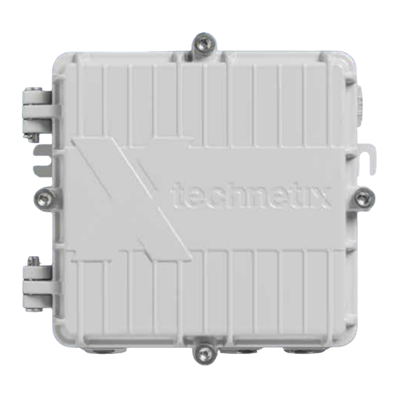
Chapter 1_Overview of the DBC-1200 Lite The Technetix DBC-1200 Lite amplifier is a cost effective end-amplifier solution for locations where modularity is not a necessity. This is a single active output, non modular version of the DBC-1200 end amplifier which uses the same management software. -
Page 7: Chapter 2 Rf Amplifier
Input RF port- PG11 thread with optional 5/8” reducing ring for 5/8” threaded connectors Port 2 RF output port- PG11 thread with optional 5/8” reducing ring for 5/8” threaded connectors Port 1 RF output port- PG11 thread with optional 5/8” reducing ring for 5/8” threaded connectors Status LED (green or red) technetix.com... -
Page 8: Chapter 3_Installing The Dbc-1200 Lite
Chapter 3_Installing the DBC-1200 Lite 3.1 Housing mounting There are two options for mounting the DBC-1200 Lite amplifier: 1. Using integrated side brackets Integrated side brackets can be used as shown below. The holes are suitable for bolts or screws with maximum diameter of 6 mm. -
Page 9: Installing Coaxial (Rf Ports)
3.2 Installing coaxial (RF ports) The DBC-1200 Lite amplifier has one input RF port and two non power-passing RF output ports (Port 1 and Port 2). All RF ports are PG11 threaded and are protected by plastic dust covers which must be removed before installing the coaxial connectors. -
Page 10: Closing Amplifier Lid
3.3 Closing amplifier lid When closing the amplifier lid please first use a hex key to tighten the four hand bolts lightly in the following sequence: Right hand bolt Left hand bolt Bottom bolt Top bolt Then, using a torque wrench set to a torque value of 6 Nm, go round again in sequence and tighten to the final torque setting. -
Page 11: Power Supply
The attenuator can be re-installed once the electronic input and interstage attenuator have been configured to 10 dB or more (as a starting point). 5. Switch on the power and check that the status LED is steady green when power is present. technetix.com... - Page 12 3.6 Block diagram and hardware configuration Block diagram DBC-1200 Lite DBC-1200 Lite_User Manual...
-
Page 13: Hardware And Plug-In Installation
Plug-ins The AUX locations equipped with attenuator attenuators 0 dB as standard. Removing this attenuator will interrupt the DS and US signals. The attenuators can be replaced by 4mm thick JXP style cable simulators, an equaliser or filter. technetix.com... - Page 14 Output diplex shielding is required to meet the specified flatness specifications up to 1.2 GHz. In the initial production of the DBC-1200 Lite the RF shield is glued to the diplexer. In later batches the shield is held in place by a plastic clip.
-
Page 15: Output Diplexer Shield Transfer For The Dbc-1200 Lite
Fig. 4 Fig. 5 IMPORTANT: The diplexer must be removed with a Technetix diplexer extractor tool (Fig. 6 and 7), do not remove the diplexer PCB with pliers. Extraction MUST be done in a straight 90 degrees angle. Fig. 6 Fig. -
Page 16: Programming And Alignment
3.8 Programming and alignment Guidance ˺ The best downstream RF input level at the first amplifier stage is 72 dBµV (12 dBmV) when all the channels are flat. ˺ The total amplifier DS gain (with 0 dB attenuation) is 44 dB. Hybrid in high power mode The maximum RF output level loaded with 120 QAM channels 8 MHz is 112 dBµV (52 dBmV) with 9 dB tilt. - Page 17 Electronic setup of downstream and upstream Using a laptop with the Technetix BLL software installed connect to the amplifier with the appropriate USB-A to USB-A lead. The amplifier must be powered before you can configure it. (Fig. 8) Fig. 8 The BLL software will automatically connect to the DBC-1200 Lite amplifier.
- Page 18 BLL page view - DBC-1200 Lite 1. Complete the diplexer type and end frequency Amplifier template should be set to: Free (Fig. 10). The amplifier name field is not supported for the DBC-1200 Lite. Fig. 10 Fig. 11 To prevent overdriving the RF amplifier, select 10 dB for the pre and interstage attenuator and EQ settings to 0 dB (Fig.
- Page 19 Set the return path sweep generator output to the required return path / upstream alignment level plus 20 dB to overcome the test point insertion losses. Finally, adjust the amplifier upstream tilt and the attenuation in the BLL software (Fig. 13) to obtain a flat sweep response at the correct level for the upstream network design. Fig. 13 technetix.com...
- Page 20 This document is for information only. Features and specifications are subject to change without notice. Technetix, the Technetix logo and certain other marks and logos are trade marks or registered trade marks of Technetix Group Limited in the UK and certain other countries.
Need help?
Do you have a question about the DBC-1200 Lite and is the answer not in the manual?
Questions and answers