
Related Manuals for technetix DBE-1200S


Summary of Contents for technetix DBE-1200S
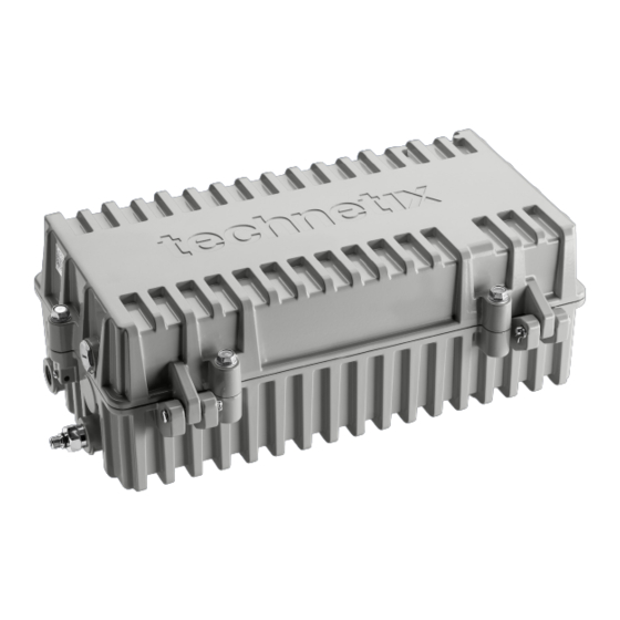
- Page 1 DBE-1200S User manual Online Email: technetix.customerservice@technetix.com Website: technetix.com 04/2019 - AE/V9...
-
Page 2: Table Of Contents
Software ....................................2 Modules available for the DBE-1200S ..........................3 Chapter 1: Overview of the DBE-1200S ..........................5 Chapter 2: DBE-1200S RF amplifier or optical node ......................6 Chapter 3: Installing the DBE-1200S amplifiers ........................11 3.1 Mounting the DBE-1200S housing ................................11 3.2 Electrical connections ..................................... 12 3.3 Closing the amplifier ...................................... -
Page 3: Precautions
AC voltages in the range of 20 – 90 VAC (110/230 VAC local power) can be present when power is connected to the DBE-1200S. Observe all notes and cautions in this user manual. Opening or removing the equipment cover may expose you to dangerous voltages. Refer all servicing to qualified service personnel only. -
Page 4: Software
19007113 USB A-male to B-mini 16.4 ft Software The software you require to configure a DBE-1200/DBE-1200S depends on the device you are using to connect to the modules within the amplifier: ■ Laptop – BLL software. The software is compatible with Windows OS ■... -
Page 5: Modules Available For The Dbe-1200S
Product user manual DBE-1200S Modules available for the DBE-1200S Upstream (US) DBUS-C-1 Main module: 204 MHz US amplifier 26 dB gain and IDS DBUS-D-1 Bridger module: 204 MHz upstream amplifier 26 dB gain and IDS Downstream (DS) DBDS-B-4-1 Main: 1.2 GHz DS amplifier 44 dB - 49 dbmV output DBDS-B-4-ET Main: 1.2 GHz DS amplifier 44 dB - 49 dbmV output –... - Page 6 A range of field replaceable, plug-in diplex filters: DBDIP-01-W 65/85 MHz diplexer DBDIP-02-W 85/105 MHz diplexer DBDIP-03-W 204/258 MHz diplexer DBDIP-04-W 42/54 MHz diplexer DBDIP-05-W 85/102 MHz diplexer Power Supply DBPSU-07-1 DBE 90 W POWER SUPPLY 90 VAC 04/2019 - EN/V9 Technetix Group Limited...
-
Page 7: Chapter 1: Overview Of The Dbe-1200S
JXP module (available in 1 to 7 and 9 to 15 dB tilt values for applications up to 1.2 GHz). The DBE-1200S has a highly efficient long-life switched-mode 90 W power supply (DBPSU-07-1) to provide power, with ample margin, to the internal electronics. -
Page 8: Chapter 2: Dbe-1200S Rf Amplifier Or Optical Node
Product user manual DBE-1200S Chapter 2: DBE-1200S RF amplifier or optical node DBE-1200S RF amplifier Item No. Description Item No. Description Removable power supply Input diplex filters; 42/54, 65/85, 85/102, 85/105 and 204/258 options available (one place) Main upstream amplifier module (one place) Output diplex filters;42/54, 65/85, 85/102, 85/105 and 204/258... - Page 9 -20 dB DOCSIS testpoint transponder -20 dB -20 dB -20 dB testpoint testpoint testpoint DBDCM-X-X control module DBDS-B-x-xx downstream DBDS-F-x-xx DBDS-F-x-xx Auto fuses Power supply Local power Port 3 Port 2 Port 1 input port 04/2019 - EN/V9 Technetix Group Limited...
- Page 10 Product user manual DBE-1200S DBE-1200S optical node Downstream optical Upstream optical receivers transmitters Fiber management tray 04/2019 - EN/V9 Technetix Group Limited...
- Page 11 -20 dB -20 dB testpoint testpoint DBDCM-X-X control module DBRX optical receiver DBRX optical receiver DBRX optical receiver Auto fuses Power supply Local power Port 3 Port 2 Port 1 input port 04/2019 - EN/V9 Technetix Group Limited...
- Page 12 In a hybrid configuration all of the upstream and downstream connections to the headend are through fiber. Here is an example hybrid configuration of the DBE-1200S with one upstream optical transmitter module with two lasers, and a second upstream optical transmitter module with one laser, and one downstream optical receiver feeding two downstream bridger amplifier modules.
-
Page 13: Chapter 3: Installing The Dbe-1200S Amplifiers
5/16" (8 mm) in length through the back board that the amplifier will be mounted onto. The total bolt length should be 5/16" (8 mm) + back board thickness + washer thickness. Mounting holes on the centerline of the back of the DBE-1200S housing are spaced 12-1/16" on-center. They are 5/16"-18 UNC x 11/32" (9 mm) deep. -
Page 14: Electrical Connections
= 1.2" (30.5 mm). Tighten the connectors into the housing in accordance with the connector manufacturer’s specification. The maximum torque force for the coaxial connector and 5/8" adapter ring is 14.75 ft*lb (20 N*m). 04/2019 - EN/V9 Technetix Group Limited... -
Page 15: Closing The Amplifier
A good lid to housing contact for the dissipation of amplifier heat. The lid acts as a radiator when it is correctly secured, keeping the amplifier operating temperature within operating limits when installed as recommended. 04/2019 - EN/V9 Technetix Group Limited... -
Page 16: Configuring The Power Supply Unit (Psu)
Referring to the network design documentation, remove any fuses not required for passing power. Remove fuses on the output ports of the Ext. power port DBE-1200S if it is not necessary to carry power. 04/2019 - EN/V9 Technetix Group Limited... -
Page 17: Powering Up The Amplifier
AC power. Then check that the amplifier DBDCM module LED (DBDCM-A-x = red, DBDCM-B-x = green) is illuminated. The LED on the control module indicates that the DBE-1200S amplifier is powered up when it is illuminated. 04/2019 - EN/V9... -
Page 18: Downstream Activation
Connect a spectrum analyzer to the input -20 dB test point, then measure and record the RF pilot frequencies’ input levels as per the design drawings. DBE-1200S input testpoint Note: Ensure all amplifier ports are connected to a 75 Ω terminated load so that the RF test instrument readings are correct. - Page 19 Note: For advanced settings and configurations, please refer to the latest release of our BLL, BLA, or T-Box Using a laptop with the Technetix BLL software installed or an Android device with the Technetix BLA software installed, connect the laptop or Android device to the amplifier through the USB connection.
- Page 20 Product user manual DBE-1200S BLx Screen when connected to DBE-1200S optical node (hybrid) Set the Amplifier Type (End, Single, Group, Trunk etc.) to its respective application followed by the Diplexer Type and the upper equalizer hinge point, End Frequency. Once these values are set in the application, click on...
- Page 21 Once the amplifier downstream/forward is commissioned, the software values can be recorded on the PSU lid label using a fine tip permanent marker pen. They can also be saved electronically. To save the amplifier settings electronically, enter the amplifier ID number into the Amplifier name field as shown below. 04/2019 - EN/V9 Technetix Group Limited...
- Page 22 The file name will appear as the amplifier name as in the screen shot below and the date at time of saving (For example: '16th and Pearl 13-Jul-2017.xml') and can be modified by the user. 04/2019 - EN/V9 Technetix Group Limited...
-
Page 23: Upstream Activation
CW carriers at 16 and 64 MHz at a 40 dBmV output level. Using a laptop with the Technetix BLL software installed or an Android device with the Technetix BLA software installed, connect the appropriate USB lead between the laptop and the amplifier control module. Start the BLx software on the computing platform. - Page 24 Advise the technician at the amplifier being setup to adjust the upstream tilt so that the two CW signals are at the same level. Equalizer (dB) 04/2019 - EN/V9 Technetix Group Limited...
- Page 25 RF forward data to the -20 dB input monitoring test point. Using the BLL software, adjust the amplifier upstream tilt then the attenuation to obtain a flat sweep response at the correct level for the upstream network design. 04/2019 - EN/V9 Technetix Group Limited...
- Page 26 Next click on the Tools tab and then click on Save current state to file to save the setting to a suitable location on the laptop. Filename will be the amplifier name as in the screenshot and the date at time of saving. 04/2019 - EN/V9 Technetix Group Limited...
-
Page 27: Chapter 4: Maintenance
Remove the PSU from the DBE-1200 housing. Installation is the reverse of removal: Place the PSU into the lid and secure the PSU into place with the four screws. Connect the electrical connectors to the PSU. Apply line power. 04/2019 - EN/V9 Technetix Group Limited... -
Page 28: Amplifier Module Replacement
To install the module, place it into the control module slot and push firmly and squarely down onto the unit until it is fully seated. Secure it by tightening the two screws to a torque value of 1.1 ft*lbs (1.5 N*m). 04/2019 - EN/V9 Technetix Group Limited... - Page 29 DBE-1200S Grip here Diplex filters To remove a diplex filter: Either place a Technetix DBGB-A-1 Digital Broadband Diplex grabber tool on the PCB, or grip the center of the PCB with a pair of linesman’s pliers, and gently pull out the diplex filter vertically, avoiding risk of damage to the connectors.
-
Page 30: Chapter 5: Optical Node 1X1 To 3X3
Chapter 5: Optical node 1x1 to 3x3 5.1 General installation If the DBE-1200S optical node is purchased then the inner fibers are already pre-installed inside the tray, including any optional WDMs, and are connected to the SC/APC connectors. Powering the node can either be done through the input port or through an external power supply plugged into the socket inside of the amplifier. -
Page 31: Upstream Connection
Depending on the number of upstream channels, you can theoretically divide the 100% OMI available over the respective channels. The higher the OMI percentage, the better the uplink performance. The upstream RF level can be measured by using an MCX Connector. Technetix part number 19011201 is an MCX to F-connector adapter. DBLB testpoint... -
Page 32: Cwdm Applications
5.4 CWDM Applications Technetix can supply tube-style and cassette style CWDM modules enabling single fiber applications. They are available in 2, 4 & 8 channel configuration. The common port is used to connect the external fiber. All other connections are made to the dedicated wavelengths of the CWDM module. -
Page 33: Software Settings
The RF end stage is controllable and can be set to high or low power mode. When maximum output power is not required it can be configured to low power, saving two watts power consumption. 04/2019 - EN/V9 Technetix Group Limited... -
Page 34: Upgrading An Rf Amplifier Into An Optical Node
You can quickly and easily upgrade an RF amplifier to an optical node by going through a few simple steps: Remove the metal RF shield from the input diplexer and pull the input diplexer straight out with either linesman’s pliers or Technetix diplexer removal tool. Reinstall the RF shield. Input diplexer with... - Page 35 Install the fiber management tray in the lid and install the fiber cables as shown, being careful to ensure that the fibers are securely captive in the fiber management hinge. Insert the SC/APC connectors into the receptacles. 04/2019 - EN/V9 Technetix Group Limited...
- Page 36 Connect the USB cable to the digital control module and configure the settings using the BLx software. Remove the USB cable and close the amplifier ensuring that the bolts are secured correctly as described in Chapter 3.3 (page 13). 04/2019 - EN/V9 Technetix Group Limited...
-
Page 37: Optical Modules
Terminating board (also called a bypass board) in case of a single upstream in a DBE for the secon slot in DBTX-A-1 19011201 MCX to F-female adapter for measuring upstream RF level Other output power and wavelength options are available, please contact your local sales representative for further information. 04/2019 - EN/V9 Technetix Group Limited... - Page 38 © 2019 Technetix Group Limited. This document is provided for information purposes only and does not constitute an offer, a quotation or any other type of contractual document capable of acceptance. Features and specifications are subject to change without notice. Technetix, the Technetix logo, Ingress Safe and Modem Safe logos and certain other marks and logos are trademarks and registered trademarks of Technetix Group Limited in the UK and certain other countries.
Need help?
Do you have a question about the DBE-1200S and is the answer not in the manual?
Questions and answers