Table of Contents
Advertisement
Quick Links
Advertisement
Table of Contents

Related Manuals for J&M Trail-Blazer TB-6000


Summary of Contents for J&M Trail-Blazer TB-6000
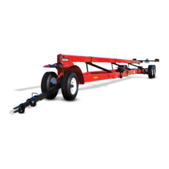
- Page 1 Operator’s Manual r a i l l a z e r TB-8000 Trail-Blazer H E A D E R T R A N S P O R T Heavy Duty 18,500 lb. Net Carrying Capacity J&M Manufacturing Co, Inc 284 Railroad Street - P.O. Box 547 | Fort Recovery, OH 45846 | Ph: (419) 375-2376 | Fax: (419) 375-2708 www.jm-inc.com...
-
Page 3: Table Of Contents
Table Of Contents 4 ..................To the Dealer 5 . -
Page 4: To The Dealer
To the Dealer TO THE DEALER Read manual instructions and safety rules. Make sure all items on the Dealer’s Pre-Delivery and Delivery Check Lists are completed before releasing equipment to the owner. The dealer must complete the Warranty Registration found on the Dealer Portal website located at dealer.jm-inc.com and return it to J&M Mfg. -
Page 5: General Information
General Information TO THE OWNER: The purpose of this manual is to assist you in operating and maintaining your header transport in a safe manner. Read it carefully. It furnishes information and instructions that will help you achieve years of dependable performance and help maintain safe operating conditions. -
Page 6: Safety Rules
Safety Rules Understand that your safety and the safety of other persons are measured by how you service and operate this machine. Know the positions and functions of all controls before you try to operate them. Check all controls in a safe area before starting your work. The safety information given in this manual does not replace safety codes, federal, state, or local laws. -
Page 7: Dimensions & Specifications
Dimensions & Specifications TB-6000 Dimensions 32’-0” to 48’ 6’-0” 26’-0” to 30’-0” 2’-10” 6’-0” TB-8000 Dimensions 41’-0” to 58’-6” 6’-0” 26’-0” to 30’-0” 2’-10” 6’-0” Specifications TB-6000 Specifications TB-8000 4-Wheel Steer Mount Options Weight 3,500 lbs. Weight 3,800 lbs. Capacity (Net) 15,700 lbs. -
Page 8: Decals
Decals ATTENTION! BECOME ALERT! YOUR SAFETY IS INVOLVED! Replace Immediately If Damaged or Missing Description Part No. HT - Knee Brace Set Up Decal JM0026114 Warning, Tire Wheel or Lug Nut Failure Decal JM0014996 Warning - Fasten Header Securely To Transport Before Moving Decal JM0039381 J&M Oval Decal (Small) 3-5/8”... -
Page 9: Bolt Torque Specifications
Bolt Torque Specifications Always tighten hardware to these values unless a different torque or tightening procedure is listed for specific application. Fasteners must always be replaced with the same grade as specified in the manual parts list. Always use the proper tool for tightening hardware. Make sure fastener threads are clean and you start thread engagement properly. -
Page 10: Operations/Maintenance
Operations/Maintenance DANGER: BE CERTAIN THAT ALL POWER IS SHUT OFF BEFORE SERVICING THE HEADER TRANSPORT. Before the Header Transport is Put into Service: • Has the Slow-Moving Vehicle sign been properly positioned at the rear of the header transport? • Have all danger, warning, caution and important signs on the equipment been read and understood? If employees or others use or are near this equipment, make sure that they also have read and understood all danger, warning, caution and important signs on the equipment and have also read the operator’s manual. -
Page 11: Set-Up Instructions
Set-Up Instructions Note: The right and the left side of the Header Transport is determined by facing the rear of the implement. Mounting the Rear Axles • Secure the Dura-Flex Axles to the axle mounts located on the underside of the header transport main frame using (4) 5/8”... - Page 12 Set-Up Instructions Mounting the Front Fender • Slide the front fender into place and attach to the goose-neck with (6) 3/8” x 1” SF nuts and (6) 3/8” SF nuts. Mounting the Front Axle Assembly • Mount (2) wheels and tires to the hubs on the ball hitch tongue and axle assembly using the wheel nuts provided. Use a star pattern to secure the wheel rim to the hub and tighten to SAE specifications.
- Page 13 Set-Up Instructions Installing the Highway Light Kit and Wiring Harnesses Insert the main wiring harness starting with the end opposite the7-prong connector, through the grommet located at the front of the gooseneck of the header transport main frame and exit the A-frame behind the gooseneck. Extend the main wiring harness along the inside right side of the header transport main frame.
- Page 14 Set-Up Instructions Placing the Red and Silver Reflective Decals (Highway Version) • Place the reflective red and silver decals so that they are represented on at least half of the overall length of the transport. On the left side of the transport, place the decals on the upper bar. On the right side of the transport, place the decals on base unit main frame, and at the back of the unit on the upper bar, as shown below.
-
Page 15: Standard Dolly
Standard Dolly Description Part No. 6-10 Ton Inner Hitch Tongue Weldment (IT-610NS) JM0027696 Flapper Weldment (10T) JM0030414 Torsion Flex Trail-Blazer Inner Tongue Ball Hitch JM0028697 Trail-Blazer - Outer Hitch Tongue Weldment JM0030470 Hitch Extension Stop Spacer for 1-1/4” Bolt JM0027776 7/8”-9 x 2-1/4”... -
Page 16: Torsion Dolly
Torsion Dolly Description Part No. Torsion Flex Trail-Blazer Inner Tongue Clevis JM0030636 Front Torsion Dolly Axle with Brakes TB6000 (6-bolt) JM0020674 Front Torsion Dolly Axle with No Brakes TB6000 (6-bolt) JM0074126 Flapper Weldment (10T) JM0030414 Torsion Flex Outer Tongue JM0028770 Torsion Flex Trail-Blazer Inner Tongue Ball Hitch JM0028697 Compression Spring (1”... -
Page 17: Tb-6000 Rear Axles
TB-6000 Rear Axles 12 13 Description Part No. Rubber Plug for Dust Cap JM0039538 Dust Cap for EZ Grease (7,000lb) JM0035957 Aluminum Wheel Dust Cap JM0049437 9/16”-18 Conical Lugnut (4WS) (ST) JM0008525 9/16 RH 7/8 Hex 2.40 XL (Lug Nut to Aluminun Wheel) JM0044721 Spring Steel Retaining Clip JM0051458... -
Page 18: Tb-8000 Rear Axles
TB-8000 Rear Axles 12 13 Description Part No. Rubber Plug for Dust Cap JM0039538 Dust Cap for EZ Grease (7,000lb) JM0035957 Aluminum Wheel Dust Cap JM0049437 9/16”-18 Conical Lugnut (4WS) (ST) JM0008525 9/16 RH 7/8 Hex 2.40 XL (Lug Nut to Aluminun Wheel) JM0044721 Spring Steel Retaining Clip JM0051458... -
Page 19: 7K Idler Hub
7k Idler Hub Description Part No. Seal 18823 (Type A) for G783 (27001500) JM0003223 Tapered Bearing Cone 25580, 12 Ton JM0018104 14125A Roller Bearing JM0039542 1” USS Flat Washer JM0003063 1”-14 Gr2 Z Castle Hex Nut JM0002139 Cotter Pin (for 1” x 3-2/5” Clevis Pin) JM0003064 Grease Cap (Solid) for 7k Idler Hub JM0058750... -
Page 20: Header Mounts And Tie-Down Assembly
Header Mounts and Tie-Down Assembly Description Part No. Removable Header Stop Gusset JM0003075 Upper Header Wagon Mount JM0014351 3/16” x 2-1/2” Hair Clip Pin (316HP) JM0001657 Low Profile Bottom Mount Weldment 4” x 8” (Front) JM0037707 5/8”-11 x 6-1/2” Gr5 Z Carriage Bolt JM0001651 3/4”... -
Page 21: Rear Upper Bar Support
Rear Upper Bar Support Description Part No. 3/4”-10 x 2” Gr5 Z Hex Bolt JM0002106 3/4”-10 Gr2 Z Centerlock Hex Nut JM0002147 Knee Brace Bolt On Lower Weldment JM0030418 1/2”-13 x 3-1/2” Gr5 Z Hex Bolt JM0009914 Splice Clamp for 48’ Top Tube JM0012934 1/2”-13 Gr2 Z Centerlock Hex Nut JM0001511... -
Page 22: Lifting Arms & Props
Lifting Arms & Props Description Part No. 1 Upper Bar Slide Mount (UBSM-3) JM0015133 2 3/16” x 2-1/2” Hair Clip Pin (316HP) JM0001657 3 Upper Bar Support Arm (UBSA-3) JM0003077 4 Upper Bar Clamp (4x8) (UBC-3) JM0003081 5 1/2”-13 Gr5 Z SF Hex Nut JM0002153 6 3/4”... -
Page 23: Upper Bar
Upper Bar Description Part No. 4” x 8” x 32’ Upper Bar JM0008541 4” x 8” x 38’ Upper Bar JM0008542 4” x 8” x 42’ Upper Bar JM0008539 4” x 8” x 48’ Upper Bar JM0058688 Front Fender Description Part No. -
Page 24: Fender
Fender Description Part No. 2-Wheel Fender (72-1/2” Length) (WF-1) JM0030412 High Speed Header Transport Fender Bracket JM0018610 Trail-Blazer Center Fender Support Bracket Weldment (FSA-2-16) JM0030407 72” Fender Bar Right JM0017948 72” Fender Bar Left JM0017924 3/8”-16 Gr5 Z SF Hex Nut JM0002152 3/8”-16 x 1”... -
Page 25: Light Bar Extension
Light Bar Extension Description Part No. 1 1/2”-13 Gr2 Z Hex Nut JM0002124 2 Header Transport Light Bar Angle Iron Support (AIS-2) JM0001440 3 1/2”-13 x 7” Gr5 Hex Bolt JM0001595 4 Header Transport Light Mount Extension Bracket (EB-1) JM0001393 5 1/2”-13 x 1-1/2”... -
Page 26: Highway Light Bar
Highway Light Bar Description Part No. 1 Header Transport Highway Light Bar Weldment (LMB-2) JM0030217 2 1” ID x 3/16” GW x 1-3/16” GD Grommet JM0016784 3 M6-1.0 x 25 Gr5 YZ Carriage Bolt JM0019445 4 M6 Flat Washer JM0019447 5 M6-1.0 YZ SF Hex Nut JM0002156 6 License Plate Mounting Bracket (LPMB-1) -
Page 27: Ag Light Bar
Ag Light Bar Description Part No. 1 Telescoping Arm for Header Transport Light Kit (TA-1) JM0001375 2 1/2”-13 x 4” Gr5 Z Bent L Bolt JM0021419 3 Header Transport Light Mounting Bracket (LMB-1) JM0001374 4 Slow Moving Vehicle Sign Bracket JM0001645 5 Slow Moving Vehicle Sign JM0001616... -
Page 28: Lights - Ag, No Brakes
Lights - Ag, No Brakes Description Part No. 1 Header Transport Right Side LED Light Assembly JM0001682 2 Header Transport Left Side LED Light Assembly JM0001680 3 Trail-Blazer Rear Light Harness (Ag) JM0030481 4 Breakaway Switch with Cable (BAS-1) JM0001843 5 Break Away Battery Box Assembly (HSBB1) JM0001833 6 Header Transport Harness 2-to-1 Extension... -
Page 29: Lights - Ag, With Brakes
Lights - Ag, with Brakes Description Part No. 1 Header Transport Right Side LED Light Assembly JM0001682 2 Header Transport Left Side LED Light Assembly JM0001680 3 Trail-Blazer Rear Light Harness (Ag) JM0030481 4 Header Transport Harness 2-to-1 Extension JM0050904 5 Trail-Blazer Brake Harness Extension (Black and White) JM0030437 6 Trail Blazer Rear Light Harness Extension (Brown, Green, Yellow, and White) JM0030439... -
Page 30: Lights - Highway
Lights - Highway Description Part No. Red LED Brake Light & Turn Signal, Right Side (Rectangular) (Cart/HS/Box) JM0018838 Trail-Blazer Rear Light Harness (Highway) JM0030483 Rear Light Panel (3 Red Lights) JM0050902 Red LED Brake Light & Turn Signal, Right Side (Rectangular) (Cart/HS/Box) JM0018837 Trail Blazer Rear Light Harness Extension (Brown, Green, Yellow, and White) JM0030439 Side Marker Light (Main Frame) Yellow (SML-2)
Need help?
Do you have a question about the Trail-Blazer TB-6000 and is the answer not in the manual?
Questions and answers