
Subscribe to Our Youtube Channel
Related Manuals for CommTech FASTCOM SuperFASTCOM


Summary of Contents for CommTech FASTCOM SuperFASTCOM
- Page 1 (217) 352-9330 | Click HERE Find the Commtech SuperFastcom-RS-422 / 485 at our website:...
- Page 2 ™ A ASTCOM DAPTERS SuperFASTCOM Four Channel High-Speed Synchronous Serial Adapter for PCI Bus Hardware Reference Manual Manufactured by: 9011 E 37th St N Wichita KS 67226-2006...
- Page 4 COPYRIGHT (C) 2001, 2002, 2003, 2004, 2005 All rights reserved, including those to reproduce this document or parts thereof in any form without permission in writing from Commtech, Inc. FASTCOM is a trademark of Commtech, Inc. Microsoft is a registered trademark of Microsoft Corporation.
- Page 5 REVISION NOTES REVISION PAGE NUMBER CHANGES MADE Revised Windows 2000 test procedure Changed warranty to 2 years Added SuperFASTCOM Cable to packing list Added link to installation manual Updated contact information Removed RS-530 references Changed board revision level on CE certificate Removed unnecessary register setup information and repaginated...
-
Page 6: Table Of Contents
CONTENTS “CE” CERTIFICATE ......................1 INTRODUCTION Description / Block Diagram .................... 3 Specifications / Features ....................4 Board Layout ........................5 Communications Overview ....................6 Comparison to ESCC Family................... 8 CABLE Cable Configuration......................9 DB25 Connector Description ..................10 INSTALLATION Hardware Installation..................... -
Page 8: Ce" Certificate
EUROPEAN UNION DECLARATION OF CONFORMITY Information Technology Equipment The Company COMMTECH, INC. declares under its own and full responsibility that the product " SuperFastcom - Revision 2.0 " on which is attached this Certificate is compliant to the "89/336/EEC" Directive, amended by 92/31/EEC and 93/88/EEC. -
Page 10: Introduction
INTRODUCTION The new SuperFASTCOM PCI adapter is a very high-speed, four channel, synchronous serial communications adapter designed for Windows- and LINUX-based industrial/commercial systems. Its outstanding features include data rates up to 40 Mbits/s and the ability to buffer up to 4 Gigabytes of data (Windows 2000) in system memory. The SuperFASTCOM supports standard synchronous protocols (HDLC, SDLC) and their variations, as well as standard asynchronous data formats at data rates up to 40 Mbits/s. -
Page 11: Specifications / Features
SPECIFICATIONS: COMMUNICATION CONTROLLER: INFINEON 20534 OS SUPPORT: Windows XP, 2000, NT4; Linux DATA RATE: All baud rates up to 40 Mbps DATA BUFFERING: Up to 4 Gbytes (Windows) Up to 52 Mbytes per channel (LINUX) DRIVERS/RECEIVERS: High Speed RS-422/RS-485 SIGNALS: TxD, RxD, RTS, CTS, DCD, TT, RT, ST CONNECTOR CONFIGURATION: DB-78 to four DB-25 connectors... -
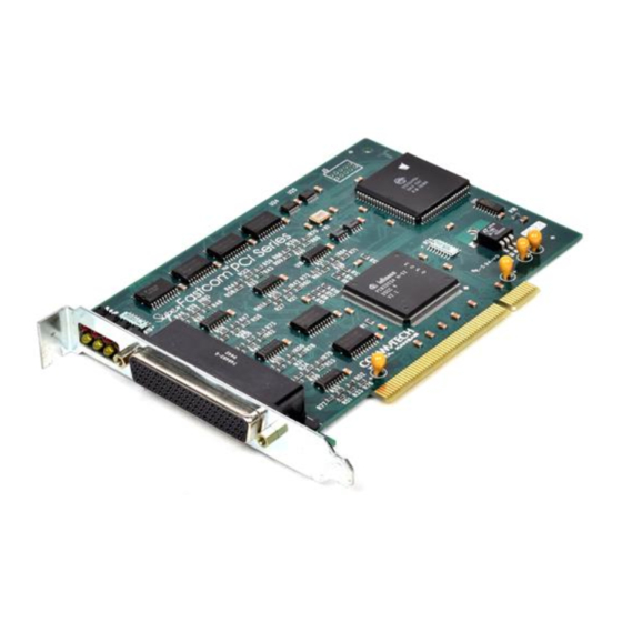
Page 12: Board Layout
SuperFASTCOM BOARD LAYOUT TRANSMIT/ RECEIVE STATUS LEDs DB78 CONNECTOR Commtech, Inc. Wichta, KS PACKING LIST: SuperFASTCOM Card SuperFASTCOM Cable FASTCOM CD If an omission has been made, please call technical support for a replacement. -
Page 13: Communications Overview
COMMUNICATIONS OVERVIEW HDLC/SDLC Protocol Modes - Automatic flag detection and transmission - Shared opening and closing flag - Generation of interframe-time fill ’1’s or flags - Detection of receive line status - Zero bit insertion and deletion - CRC generation and checking (CRC-CCITT or CRC-32) - Transparent CRC option per channel and/or per frame - Programmable Preamble (8 bit) with selectable repetition rate - Error detection (abort, long frame, CRC error, short frames) - Page 14 - Data overflow and under run detection - Timer Protocol Support Address Recognition Modes - Mode 0 - No address recognition - Mode 1 - 8-bit (high byte) address recognition - Non-Auto Mode - 8-bit (low byte) or 16-bit (high and low byte) address recognition General On-chip Rx and Tx data buffer (the buffer size is 128 32-bit words each) Programmable buffer size in transmit direction per channel;...
-
Page 15: Comparison To Escc Family
SuperFASTCOM / ESCC FAMILY COMPARISON Enhancements to the ESCC Serial Core The SuperFASTCOM adapter contains the core logic of the ESCC2 V3.2A as the heart of the device. Some enhancements are incorporated in the SuperFASTCOM. These are: 16-Kbyte packet length byte counter Enhanced address filtering (16-bit maskable) Enhanced time slot assigner Support of high data rates (45 Mbit/s for DS3 or 52 Mbit/s for OC1). -
Page 16: Cable Configuration
CONFIGURATION FOR SuperFASTCOM CABLE ASSEMBLY The cable provided with your SuperFastcom adapter splits each channel from the DB78 to into four DB 25 male connectors. DB78 PIN NUMBER SIGNAL DB25 # CHANNEL 1 CHANNEL 2 CHANNEL 3 CHANNEL 4 RTS- RTS+ CTS- CTS+... -
Page 17: Db25 Connector Description
SuperFASTCOM DB25 CTS+ CABLE CONNECTOR DESCRIPTION PROGCLK- (CH1) DCD- DCD+ PROGCLK+ (CH1) RTS+ CTS- RTS- PIN DESCRIPTIONS PIN# DESCRIPTION 422 TYPE CONNECTED TO SHIELD/GROUND SIGNAL/GROUND TRANSMIT DATA TRANSMIT DATA RECEIVE DATA RECEIVE DATA REQUEST TO SEND RTS- REQUEST TO SEND RTS+ CLEAR TO SEND CTS-... -
Page 18: Installation
INSTALLATION Important: Observe Electrostatic Discharge (ESD) precautions when handling the SuperFASTCOM board. Unpack the SuperFASTCOM adapter. Keep the box and static bag for warranty repair returns. Select an open PCI slot in your PC. The SuperFastcom requires that the selected PCI slot be capable of bus mastering. The card will not function correctly if installed into a non-bus mastering slot. -
Page 19: Software Utilities
3 h SOFTWARE UTILITIES These programs and their source can be found on the Fastcom CD or downloaded from our website at http://www.commtech-fastcom.com/. They are meant to be used as educational tools and programming references when designing your own software. - Page 20 o Type a message: “Hello, world”. o What you type should show up under “Transmit” in the window. o Select “Send” from the menu. o The message will appear in red under “Received”. o To open a different port, either select “File->New” or “Disconnect” from the menu. •...
-
Page 21: Programming
PROGRAMMING Refer to the enclosed FASTCOM CD for example programs, product updates, and software for testing your installation. Refer to the Infineon PEB 20534 User's Manual for register information. Local Bus Interface for PEB 20534 - Byte accesses Register at offset 0 Register at offset 1 Channel 1 Channel 3... - Page 22 TT constantly enabled – (default) for RS-422 communications TT enabled only when RTS is on – turns off the transmit clock when it is not actively sending data so that it does not contend with another transmitter on the clock bus Offset 2 –...
-
Page 23: Memory Management
MEMORY MANAGEMENT High-speed communications requires that large amounts of transmitted/received data be buffered so as to prevent data loss and maintain data throughput. The SuperFASTCOM is designed to utilize system memory directly, bypassing the system processor. SuperFASTCOM accesses system memory through high-speed PCI Bus Mastering, using its on-board bus master controller and supplied software. - Page 24 RS-422 / RS-485 Most engineers have worked with RS-232 devices at least once in their career. If you have never worked with RS-422 or RS-485 devices, you will be pleased to know that working with the SuperFASTCOM is not much different from working with an RS-232 device. The RS-422 standard was developed to correct some of the deficiencies of RS-232.
-
Page 25: Termination Resistance
TERMINATION RESISTANCE In both the RS-422 and the RS-485 mode, the receiver end of the cable between two stations must be terminated with a resistor equal to the characteristic impedance of the wire. This is to prevent signal reflections in the wire and to improve noise rejection. However, you do not need to add a terminator resistor to your cables when you use the SuperFastcom. -
Page 26: Programmable Clock Generators
PROGRAMMABLE CLOCK GENERATORS The SuperFastcom features two Programmable Clock Generators. Each is a Cypress ICD2053B chip, which offers a fully user-programmable phase-locked loop clock pulse generator in a single 8-pin package. The output of the generator may be changed "on the fly" to any desired frequency value. -
Page 27: Erratta
ERRATA The errata listed below are known issues with the either Superfastcom board or the PEB20534 controller itself. For more information regarding any of these issues, please contact Commtech technical support. • Serial Bus Configuration Timing Modes The SuperFastcom was not designed to make use of Serial Bus Configuration timing modes 1 and 2. - Page 28 Workaround: It is recommended to disable shared flag transmission by setting bit CCR1:SFLAG = ’0’. Note: Reception of frames with shared flags is always possible and neither affected by this erratum nor by setting of bit CCR1:SFLAG. Thus networking with other HDLC equipment supporting shared flags is not restricted.
- Page 29 due to one of the clocks temporarily gapped, ’CEC’ status bit must be checked for ’0’ before writing a command bit. • Carrier Auto-detect in HDLC Mode The carrier detect (CD) input pin is supposed to enable and disable reception in clock modes 0, 2, 3, 6 and 7.
-
Page 30: Technical Support
Commtech. In no case shall Commtech liability exceed the original product purchase price. If any Commtech product is damaged such that it cannot be repaired, you can return it to Commtech for replacement under our Non-Repairable Replacement policy, regardless of the cause of damage. -
Page 31: Infineon 20534 Technical Data Sheet
APPENDIX A INFINEON 20534 TECHNICAL DATA...
Need help?
Do you have a question about the FASTCOM SuperFASTCOM and is the answer not in the manual?
Questions and answers