Table of Contents
Advertisement
Available languages
Available languages
Quick Links
OPERATOR'S MANUAL
MANUAL DEL OPERADOR
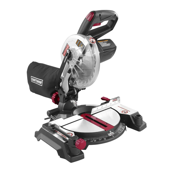
7-1/4 in., 19.2 Volt
Compound Miter Saw
Sierra ingleteadora combinada
de 7-1/4 pulg., de 19.2 V
MODEL NO. / NÚMERO DE MODELO
315.BT2010
WARNING
: To reduce the risk of injury,
the user must read and understand the
operator's manual before using this
product.
ADVERTENCIA:
Para reducir el
riesgo de lesiones, el usuario debe leer
y comprender el manual del operador
antes de usar este producto.
Customer Help Line: 1-800-932-3188
Teléfono de atención al consumidor: 1-800-932-3188
Sears Brands Management Corporation,
3333 Beverly Rd., Hoffman Estates, IL 60179 USA
Visit the Craftsman web page: www.sears.com/craftsman
Visite el sitio web de Craftsman: www.sears.com/craftsman
990000668
10-1-13 (REV:03)
Save this manual for future reference
Guarde este manual para futuras consultas
BATTERY AND CHARGER
SOLD SEPARATELY
BATERÍA Y CARGADOR SE
VENDEN POR SEPARADO
Advertisement
Table of Contents

Related Manuals for Craftsman 315.BT2010


Summary of Contents for Craftsman 315.BT2010
- Page 1 VENDEN POR SEPARADO Sears Brands Management Corporation, 3333 Beverly Rd., Hoffman Estates, IL 60179 USA Visit the Craftsman web page: www.sears.com/craftsman Visite el sitio web de Craftsman: www.sears.com/craftsman Save this manual for future reference Guarde este manual para futuras consultas 990000668...
-
Page 2: Table Of Contents
For warranty coverage details to obtain free replacement, visit the web site: www.craftsman.com This warranty does not cover the bits, which are expendable parts that can wear out from normal use within the warranty period. -
Page 3: General Safety Rules
GENERAL SAFETY RULES USE RECOMMENDED ACCESSORIES. Consult the WARNING: Read and understand all instructions. operator’s manual for recommended accessories. The Failure to follow all instructions listed below, may use of improper accessories may result in injury. result in electric shock, fire and/or serious personal ... -
Page 4: Specific Safety Rules
GENERAL SAFETY RULES NEVER START A TOOL WHEN ANY ROTATING appliance/battery pack/charger correlation supplement COMPONENT IS IN CONTACT WITH THE WORK- 988000-272. PIECE. WHEN BATTERY PACK IS NOT IN USE, KEEP IT DO NOT OPERATE A TOOL WHILE UNDER THE AWAY FROM OTHER METAL OBJECTS LIKE PAPER INFLUENCE OF DRUGS, ALCOHOL, OR ANY CLIPS, COINS, KEYS, NAILS, SCREWS, OR OTHER... - Page 5 SPECIFIC SAFETY RULES NEVER hand hold a workpiece that is too small to be ALWAYS STAY ALERT! Do not allow familiarity (gained clamped. Keep hands clear of the cutting area. from frequent use of your saw) to cause a careless mistake.
-
Page 6: Symbols
SYMBOLS The following signal words and meanings are intended to explain the levels of risk associated with this product. SYMBOL SIGNAL MEANING Indicates an imminently hazardous situation, which, if not avoided, will result DANGER: in death or serious injury. Indicates a potentially hazardous situation, which, if not avoided, could result WARNING: in death or serious injury. -
Page 7: Glossary Of Terms
GLOSSARY OF TERMS Anti-Kickback Pawls (flooring, radial arm, and table saws) Push Blocks (jointer planers) A device which, when properly installed and maintained, Device used to feed the workpiece over the jointer planer is designed to stop the workpiece from being kicked back cutterhead during any operation. -
Page 8: Features
FEATURES PRODUCT SPECIFICATIONS Cutting Capacity with Miter at 0°/Bevel 0°: Maximum lumber sizes ..... 1-1/2 in. x 4-1/4 in. Arbor ................. 5/8 in. Cutting Capacity with Miter at 45°/Bevel 0°: Blade Diameter ............7-1/4 in. Maximum lumber sizes ......1-1/2 in. x 3 in. No Load Speed ........ - Page 9 FEATURES KNOW YOUR COMPOUND MITER SAW LOCK See Figure 1. MITER The safe use of this product requires an understanding of LOCK LEVER the information on the tool and in this operator’s manual as well as a knowledge of the project you are attempt- ing.
-
Page 10: Tools Needed
FEATURES SWITCH TRIGGER SWITCH LOCK See Figure 4. The saw will not start until you depress the switch lock with your thumb then squeeze the switch trigger. To prevent unauthorized use of the compound miter saw, SWITCH remove the battery pack, and lock the switch in the off PADLOCK TRIGGER position. -
Page 11: Loose Parts
LOOSE PARTS LIST The following items are included with your compound miter saw: Dust Bag Rear Bracket/Carrying Handle Work Clamp Operator’s Manual (not shown) Blade Wrench WORK CLAMP DUST BLADE WRENCH REAR BRACKET/ CARRYING HANDLE Fig. -
Page 12: Assembly
ASSEMBLY UNPACKING INSTALLING THE REAR BRACKET/CARRYING HANDLE This product requires assembly. See Figure 7. Carefully lift miter saw base from the carton by the “D” handle and the saw base, and place it on a level work surface. WARNING: A rear bracket is included with this mi- ter saw to prevent tipping if the saw arm is released WARNING:... - Page 13 ASSEMBLY DUST BAG WARNING: Always make sure the compound miter See Figure 9. saw is securely mounted to a workbench or an ap- A dust bag is provided for use on this miter saw. It fits proved workstand. Failure to heed this warning can over the exhaust port on the upper blade guard.
- Page 14 ASSEMBLY WORK CLAMP See Figure 10. The work clamp provides greater control by clamping the workpiece to the fence. It also prevents the workpiece from creeping toward the saw blade. This is very helpful when cutting compound miters. Depending on the cutting operation and the size of the workpiece, it may be necessary to use a C-clamp instead of the work clamp to secure the workpiece prior to making the cut.
- Page 15 ASSEMBLY TO INSTALL/REPLACE THE BLADE NOTE: BEFORE USE, REPLACE SCREW AND See Figures 11 - 12. TIGHTEN SECURELY TO PREVENT GUARD WARNING: MOVEMENT A 7-1/4 in. blade is the maximum blade BLADE capacity of the saw. Never use a blade that is too BOLT thick to allow outer blade washer to engage with COVER...
- Page 16 ASSEMBLY SOCKET HEAD SCREW(S) SOCKET HEAD MITER SCREW(S) LOCK MITER LEVER FENCE BLADE FRAMING MITER SQUARE TABLE MITER VIEW OF BLADE SQUARE WITH FENCE Fig. 14 FENCE Fig. 13 NOTE: Many of the illustrations in this manual show only portions of the compound miter saw. This is intentional so that we can clearly show points being made in the MITER illustrations.
- Page 17 ASSEMBLY SQUARING THE BLADE TO THE MITER TABLE See Figures 17 - 20. BEVEL Remove the battery pack from the tool. LOCK Pull the saw arm all the way down and engage the lock KNOB pin to hold the saw arm in transport position. ...
-
Page 18: Operation
OPERATION TO INSTALL BATTERY PACK WARNING: Do not allow familiarity with tools to See Figure 21. make you careless. Remember that a careless frac- Place battery pack in the saw. Align raised rib on bat- tion of a second is sufficient to inflict serious injury. tery pack with groove inside saw. - Page 19 OPERATION CUTTING WITH YOUR COMPOUND CROSS CUT MITER SAW WARNING: When using a work clamp or C-clamp to secure your workpiece, clamp workpiece on one side of the blade only. The workpiece must remain free on one side of the blade to prevent the blade from binding in workpiece.
- Page 20 OPERATION Grasp the saw handle firmly. Depress the switch lock INDICATOR POINT with thumb then squeeze the switch trigger. Allow sev- eral seconds for the blade to reach maximum speed. Slowly lower the blade into and through the workpiece. ...
- Page 21 OPERATION COMPOUND MITER CUT Slowly lower the blade into and through the workpiece. Release the switch trigger and allow the saw blade to stop rotating before raising the blade out of the workpiece. Wait until the blade stops before removing the workpiece from the miter table.
- Page 22 OPERATION Place the workpiece flat on the miter table with one edge securely against the fence. If the board is warped, place the convex side against the fence. If the concave edge of a board is placed against the fence, the board could collapse on the blade at the end of the cut, jam- ming the blade.
- Page 23 OPERATION CUTTING COMPOUND MITERS To aid in making the correct settings, the compound angle setting chart below has been provided. Since compound cuts are the most difficult to accurately obtain, trial cuts should be made in scrap material, and much thought and planning made, prior to making the required cut.
- Page 24 OPERATION CUTTING CROWN MOLDING When setting the bevel and miter angles for compound miters, remember that the settings are interdependent; This compound miter saw does an excellent job of cutting changing one angle changes the other angle as well. crown molding. In general, compound miter saws do a Keep in mind that the angles for crown molding are very better job of cutting crown molding than any other tool precise and difficult to set.
- Page 25 OPERATION Bevel Angle Type of Cut Setting Left side, inside corner 1. Top edge of molding against fence 33.85° 2. Miter table set right 31.62° 3. Save left end of cut Right side, inside corner 1. Bottom edge of molding against fence 33.85°...
-
Page 26: Adjustments
ADJUSTMENTS POSITIVE STOP ADJUSTMENTS WARNING: To prevent accidental starting that See Figure 32. could cause serious personal injury, always remove NOTE: These adjustments were made at the factory and the battery pack from the tool when assembling normally do not require readjustment. parts. - Page 27 ADJUSTMENTS TO ADJUST THE MITER LOCK LEVER See Figure 33. Prior to squaring the saw blade to the fence, check and adjust the miter lock lever, if needed. In the “locked” posi- tion, the action of fully locking the miter lock lever should feel tight and secure.
-
Page 28: Maintenance
MAINTENANCE LUBRICATION WARNING: When servicing, use only identical All of the bearings in this tool are lubricated with a suffi- replacement parts. Use of any other parts can create cient amount of high grade lubricant for the life of the unit a hazard or cause product damage. - Page 29 NOTES 29 — English...
-
Page 34: Reglas De Seguridad Generales
REGLAS DE SEGURIDAD GENERALES DÉ MANTENIMIENTO CON CUIDADO A LAS HERRAMIENTAS. Mantenga afiladas y limpias las ADVERTENCIA: Lea y comprenda todas las in- herramientas para obtener de las mismas un strucciones. El incumplimiento de las instrucciones desempeño mejor y más seguro. Siga las instrucciones señaladas abajo puede causar descargas eléctricas, correspondientes al cambio y lubricación de accesorios. -
Page 35: Reglas De Seguridad Específicas
REGLAS DE SEGURIDAD GENERALES UTILICE LAS HERRAMIENTAS ELÉCTRICA SÓLO inadecuados. La sierra tiene capacidad para hojas hasta CON EL PAQUETE DE BATERÍAS ESPECÍFICAMENTE de un diámetro de 7-1/4 pulg. INDICADO. El empleo de baterías diferentes puede ANTES DE EFECTUAR UN CORTE VERIFIQUE presentar un riesgo de incendio. - Page 36 REGLAS DE SEGURIDAD ESPECÍFICAS trabajo en cualquier operación. Si se utilizan juntos una interruptor de corriente, retire la clavija del suministro de corriente y llame a un técnico para que reemplace toda prensa para pieza de trabajo y un tope de longitud, pieza dañada, faltante o defectuosa antes de reanudar el ambos deben estar instalados en el mismo lado de la trabajo.
-
Page 37: Símbolos
SÍMBOLOS Las siguientes palabras de señalización y sus significados tienen el objeto de explicar los niveles de riesgo relacionados con este producto. SÍMBOLO SEÑAL SIGNIFICADO Indica una situación peligrosa inminente, la cual, si no se evita, causará la muerte PELIGRO: o lesiones serias. -
Page 38: Glosario De Términos
GLOSARIO DE TÉRMINOS Trinquetes anticontragolpe (sierras cortar pisos, radiales Bloques empujadores (para cepillos de juntas) y de mesa) Son dispositivos empleados para avanzar la pieza de trabajo por Es un dispositivo, el cual, cuando se instala y da mantenimiento el cepillo de juntas durante cualquier operación. Este medio ayuda correctamente, sirve para detener la pieza de trabajo para no al operador a mantener las manos alejadas de la cabeza de corte. -
Page 39: Características
CARACTERÍSTICAS ESPECIFICACIONES DEL PRODUCTO Capacidad de corte con inglete a 45°/bisel a 0°: Tamaños máximos Árbol ................5/8 pulg. de la madera ....38 mm x 76 mm (1-1/2 pulg. x 3 pulg.) Diámetro de la hoja .............7-1/4 pulg. Capacidad de corte con inglete a 0°/bisel a 45°: Velocidad en vacío .......... - Page 40 CARACTERÍSTICAS PASADOR DE FAMILIARÍCESE CON LA SIERRA INGLETEADO- SEGURIDAD RA COMBINADA Vea la figura 1. PALANCA El uso seguro que este producto requiere la compren- DE FIJACIÓN sión de la información impresa en la herramienta y en DE INGLETE el manual del operador así como ciertos conocimientos sobre el proyecto a realizar.
-
Page 41: Herramientas Necesarias
CARACTERÍSTICAS GATILLO DEL INTERRUPTOR GATILLO DEL INTERRUPTOR Vea la figura 4. La sierra no funcionará hasta que oprima el seguro del interruptor con el pulgar y oprima el gatillo del interruptor. Para evitar el uso no autorizado de la sierra ingleteadora combinada, retire el paquete de baterías, y asegurar el CANDADO GATILLO DEL... -
Page 42: Piezas Sueltas
LISTA DE PIEZAS SUELTAS Vienen incluidos los siguientes artículos con la sierra ingleteadora combinada: Saco captapolvo Soporte trasero/mango de acarreo Prensa de trabajo Manual del operador (no se muestra) Llave de hoja PRENSA DE TRABAJO SACO CAPTAPOLVO LLAVE DE... -
Page 43: Armado
ARMADO DESEMPAQUETADO ADVERTENCIA: No encienda la sierra ingleteadora Este producto requiere armarse. combinada sin revisar para ver si hay interferencia en- Retire cuidadosamente la base de la sierra ingleteadora tre la hoja y la guía de ingletes. Puede dañarse la hoja de la caja, utilizando el mango en forma de “D”... - Page 44 ARMADO SACO CAPTAPOLVO ADVERTENCIA: Siempre asegúrese de que la Vea la figura 9. sierra ingleteadora combinada esté firmemente Se suministra un saco captapolvo para utilizarse con la montada en un banco de trabajo o en un pedestal sierra ingleteadora. Se acopla en la abertura de salida del aprobado.
- Page 45 ARMADO PRENSA DE TRABAJO Vea la figura 10. La prensa de trabajo ofrece mayor control al prensar la pieza de trabajo contra la guía. También evita que la pieza de trabajo avance hacia la hoja de la sierra. Esto es muy útil al efectuar cortes a inglete combinados.
- Page 46 ARMADO PARA INSTALAR O REEMPLAZAR LA HOJA NOTA: ANTES DE USO, VUELVA A COLOCAR EL TORNILLO Y APRIÉTELO FIRMEMENTE PARA Vea las figuras 11 y 12. PREVENIR EL MOVIMIENTO DE PROTECCIÓN ADVERTENCIA: La sierra tiene capacidad para TAPA DEL hojas hasta de un diámetro de 7-1/4 pulg. Nunca TORNILLO DE PERNO DE utilice una hoja tan gruesa que la arandela exterior...
- Page 47 ARMADO TORNILLO(S) DE CABEZA HUECA TORNILLO(S) DE CABEZA HUECA PALANCA DE FIJACIÓN DE GUÍA DE INGLETE INGLETES LAME ESCUADRA DE MESA DE CARPINTERO INGLETES VISTA A DE LA HOJA A ESCUADRA CON LA GUÍA GUÍA Fig. 14 Fig. 13 NOTA: En muchas de las ilustraciones de este manual se muestran sólo porciones de la sierra ingleteadora combinada.
- Page 48 ARMADO ESCUADRADO DE LA HOJA CON LA MESA PERILLA DE FIJACIÓN DE BISEL DE INGLETES Vea las figuras 17 a 20. Retire de la herramienta el paquete de baterías. Tire del brazo de la sierra completamente hacia abajo y enganche el pasador de seguridad para asegurar el GUÍA DE brazo en la posición de traslado.
-
Page 49: Funcionamiento
FUNCIONAMIENTO PARA INSTALAR EL PAQUETE DE BATERÍAS ADVERTENCIA: No permita que su familar- Vea la figura 21. ización con las herramientas lo vuelva descuidado. Coloque el paquete de baterías en la sierra. Alinee la Tenga presente que un descuido de un instante es costilla realzada del paquete de baterías con la ranura suficiente para causar una lesión grave. - Page 50 FUNCIONAMIENTO FORMA DE CORTAR CON LA SIERRA CORTE TRANSVERSAL INGLETEADORA COMBINADA ADVERTENCIA: Al utilizar la prensa de trabajo o una de mano para asegurar la pieza de trabajo, sujete ésta sólo en un lado de la hoja. La pieza de trabajo debe quedar libre en un lado de la hoja para evitar que ésta se atore en la pieza de trabajo.
- Page 51 FUNCIONAMIENTO Antes de encender la sierra, efectúe una simulación de ESCALA DE BISELES la operación de corte, sólo para asegurarse de que no suceda ningún problema durante la operación de corte real. Sujete firmemente el mango de la sierra. Oprima el seguro del interruptor con el pulgar y luego oprima el gatillo.
- Page 52 FUNCIONAMIENTO Sujete firmemente la pieza con una mano y asegúrela CORTE EN INGLETE COMBINADO contra la guía. Use la prensa de trabajo optativa o una prensa de mano para asegurar la pieza de trabajo siempre que sea posible. Antes de encender la sierra, efectúe una simulación de la operación de corte, sólo para asegurarse de que no suceda ningún problema durante la operación de corte real.
- Page 53 FUNCIONAMIENTO Gire la mesa de inglete hasta no alinear el indicador con el cero de la escala de ingletes. NOTA: Usted puede localizar con rapidez los ángulos de 0˚, 15˚, 22-1/2˚, 31.62˚ y 45˚ a la izquierda o derecha a medida que gira el brazo de control.
- Page 54 FUNCIONAMIENTO CÓMO EFECTUAR CORTES A INGLETE COMBINADOS Como ayuda para realizar los ajustes correctos, se suministra la siguiente tabla de ángulos combinados. Puesto que los cortes combinados son los más difíciles de obtener, deben efectuarse cortes de prueba en material de desecho, así como una gran cantidad de reflexión y planeación, antes de efectuar el corte final.
- Page 55 FUNCIONAMIENTO CÓMO CORTAR MOLDURAS DE CORONA Al fijar los ángulos de bisel e inglete de los cortes a inglete combinados, recuerde que los ajustes son interdependi- Esta sierra ingleteadora combinada realiza una labor entes; si se cambia un ángulo se cambia el otro también. excelente para cortes de molduras de corona.
- Page 56 FUNCIONAMIENTO Ajuste del ángulo Tipo de corte de bisel Lado izquierdo, esquina interior 1. Canto superior moldura contra guía 33,85° 2. Mesa ingletes a 31,62° a la derecha 3. Guarde extremo izquierdo del corte Lado derecho, esquina interior 1. Canto inferior moldura contra guía 33,85°...
- Page 57 AJUSTES AJUSTES DE LOS TOPES ADVERTENCIA: Para evitar un arranque acciden- Vea la figura 32. tal que podría causar lesiones corporales serias, NOTA: Estos ajustes se realizaron en la fábrica y normal- siempre desmonte de la herramienta el paquete de mente no requieren reajustarse.
- Page 58 AJUSTES PARA AJUSTAR LA PALANCA DE FIJACIÓN DE INGLETES Vea la figura 33. Antes de encuadrar la segueta de la sierra a la guía, verifique y ajuste la palanca de fijación de ingletes si es necesario. En la posición “de traba”, la sensación al trabar por completo la palanca de fijación del inglete debe ser firme y segura.
-
Page 59: Mantenimiento
MANTENIMIENTO LUBRICACIÓN ADVERTENCIA: Al dar servicio a la unidad, sólo Todos los cojinetes de esta herramienta están lubricados utilice piezas de repuesto idénticas. El empleo de con suficiente cantidad de aceite de alta calidad para piezas diferentes puede causar un peligro o dañar toda la vida útil de la unidad en condiciones normales de el producto.
Need help?
Do you have a question about the 315.BT2010 and is the answer not in the manual?
Questions and answers