
Related Manuals for Hubble X-100


Summary of Contents for Hubble X-100
- Page 1 HUBBLE LITHIUM X100-48 Integrated Lithium-ion Battery User Manual Version:V2.0 Released Date:2020-06-08...
- Page 2 Quick Setup The Hubble is designed to work with 48V UPS and inverter systems and will work under AGM charge characteristics. For solar inverters that is not on the approved integration list it is recommended to set your inverter battery parameters manually to ensure your battery operates at optimal levels.
-
Page 3: Foreword
Integrated Lithium-ion Battery Pack For Solar & FOREWORD UPS User Manual FOREWORD Overview This manual describes the installation, history recording and parameter settings etc. Readers This document provides technical details regarding the tools and infrastructure used by the following users: Sales engineer ... - Page 4 Integrated Lithium-ion Battery Pack For Solar & FOREWORD UPS User Manual Used as a warning of potential dangers, if ignore this information, it may result in equipment broken, data lost, equipment performance decrease and other unpredictable result. represents the supplement information of main text to emphasize or replenish.
-
Page 5: Table Of Contents
Integrated Lithium-ion Battery Pack For Solar & DIRECTORY UPS User Manual DIRECTORY FOREWORD ............................. ii DIRECTORY ............................. iv 1 OVERVIEW ............................. 6 1.1 Product specification..............................6 1.2 Product profiles................................6 1.3 Product structure...............................7 2 ILLUSTRATION ..........................8 2.1 Panel description............................... 8 2.2 Menu operation instructions..........................13 2.3 The working principle.............................14 2.4 The product features.............................. -
Page 6: Directory
Integrated Lithium-ion Battery Pack For Solar & DIRECTORY UPS User Manual 5 SPECIFICATIONS........................33 5.1 Technical specifications............................33 5.2 The main performance index of the battery....................34 6 ENVIRONMENT PROTECTION....................36 6.1 Environmental Label............................... 36 6.2 Recycle..................................36 7 APPENDIX............................37 7.1 Connection cable..............................37 8 G-SENSOR……………………………………………………………………………………………………………………………..39 All Right Reserved ©... -
Page 7: Overview
1.1 Product specification The model of integrated lithium Ion battery (hereafter referred to as lithium battery or PACK) for Solar & UPS is the HUBBLE X-100. 1.2 Product profiles The lithium battery group is developed by Supplier. Belonging to one of the series of... -
Page 8: Product Structure
Integrated Lithium-ion Battery Pack For Solar & 1 OVERVIEW UPS User Manual The system integrates advanced battery manage system (BMS), including charge and discharge management, thermal management, communication management, balance management, data management, and realize remote centralized monitoring, remote management and maintenance of the battery. It has outstanding advantages in specific occasions, as a backup power supply is widely used in the remote access network equipment, exchange, mobile communication equipment, transmission equipment, satellite and microwave communication equipment and communication. -
Page 9: Illustration
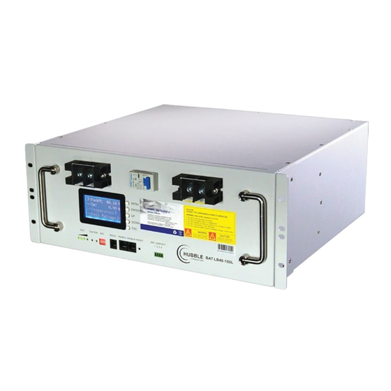
Integrated Lithium-ion Battery Pack For Solar & 2 ILLUSTRATION UPS User Manual ILLUSTRATION 2.1 Panel description The lithium battery panel as the Figure2-1 shows below. Figure2-1 Module panel description For detailed descriptions of each location, see the following figure2-2. All Right Reserved ©... - Page 10 Integrated Lithium-ion Battery Pack For Solar & 2 ILLUSTRATION UPS User Manual Figure2-2 Panel Effect Chart 3 ALM(alarm) 1 Handle 2 SOC (capacity light) 4 RUN 5 ADD 6 RS232 7 RS485 8 RESET / POWER ON 9 Dry Contact 10 Main panel 11 Mounting holes 12 Output-...
- Page 11 Integrated Lithium-ion Battery Pack For Solar & 2 ILLUSTRATION UPS User Manual When the battery is at fault, "ALM" light is red. During charging, the "RUN" light will be flashing. "RUN" and "ALM" can display the battery status, as shown in table 2-2. Table2-2 The explanation of “RUN”...
- Page 12 Integrated Lithium-ion Battery Pack For Solar & 2 ILLUSTRATION UPS User Manual Address Code PACK Explanation Definition PACK8 Use as SlavePack8 PACK9 Use as SlavePack9 PACK10 Use as SlavePack10 PACK11 Use as SlavePack11 PACK12 Use as SlavePack12 PACK13 Use as SlavePack13 PACK14 Use as SlavePack14 Address code 5 and 6 are reserved and do not play any role.
- Page 13 Integrated Lithium-ion Battery Pack For Solar & 2 ILLUSTRATION UPS User Manual When the system is in parallel mode, it can use the RS-485 serial comms for data transfer. The main system through the Master Pack to get the data for each Slave Pack.
-
Page 14: Menu Operation Instructions
Integrated Lithium-ion Battery Pack For Solar & 2 ILLUSTRATION UPS User Manual 2.2 Menu operation instructions The LCD display interface is user-friendly, as shown in figure 2-5. It provides 320 * 240 dot matrix graphic display. The LCD is able to display the alarm information in real time, and provides the historical warning records for the user to query, and provide a reliable basis for fault diagnosis. -
Page 15: The Working Principle
Integrated Lithium-ion Battery Pack For Solar & 2 ILLUSTRATION UPS User Manual Operation procedures Press once, the LCD display screen light up, then the welcome interface will be shown. Followed by the prompt and then click once to enter the main menu bar. Scroll page up and page down ,Enter the Menu screen, when the arrow... -
Page 16: The Product Features
Integrated Lithium-ion Battery Pack For Solar & 2 ILLUSTRATION UPS User Manual Figure2-6 the working principle diagram 2.4 The product features Integrated lithium battery pack for Solar & UPS has the following characteristics: The lithium iron phosphate as cathode material has a long life cycles, its safety ... - Page 17 Integrated Lithium-ion Battery Pack For Solar & 2 ILLUSTRATION UPS User Manual overcurrent alarm / alarm, environment / battery /PCBA/ battery temperature alarm, low environmental temperature alarm, battery capacity is too low, the battery temperature / voltage / current sensor failure alarm, battery failure alarm (just not cut off the monomer pressure high limit alarm) (optional), battery failure alarm (optional).
-
Page 18: Installation Guide
Integrated Lithium-ion Battery Pack For Solar & 3 INSTALLATION GUIDE UPS User Manual INSTALLATION GUIDE 3.1 Installation precaution notes Comply with local laws and regulations When operating the equipment, make certain to comply with local laws and regulations. Personnel requirements Technicians who are responsible for installation and maintenance are required to undertake strict training first. - Page 19 Integrated Lithium-ion Battery Pack For Solar & 3 INSTALLATION GUIDE UPS User Manual Lithium battery packs cannot be placed in or near garbage disposals, or accidentally dropped or placed in smaller disposal units, as their interaction with metals is likely to cause short circuits and endanger the system and personal safety.
-
Page 20: Installation Preparation
Integrated Lithium-ion Battery Pack For Solar & 3 INSTALLATION GUIDE UPS User Manual Do not install in the working environment with metal conduction type dust. Do not put anything containing corrosive gases. Do not put anything in the dust concentrated areas. ... -
Page 21: Installation Tools
Integrated Lithium-ion Battery Pack For Solar & 3 INSTALLATION GUIDE UPS User Manual accessories and order contracts should be recorded and immediately contact the local branch or office of Supplier company. The site needs to be reviewed inspected once again to make sure the audit documents are in order for the audit. -
Page 22: Installation And Wiring
Integrated Lithium-ion Battery Pack For Solar & 3 INSTALLATION GUIDE UPS User Manual Table3-3 Electrical installation tools The appearance of the tools, parameters, and names Insulated gloves Wire stripping pliers Electrical tape Power cable crimpi ng plier Table3-4 Measuring Tools The appearance of the tools, parameters, and names Clamp the flow tab 3.3 Installation and wiring... - Page 23 Integrated Lithium-ion Battery Pack For Solar & 3 INSTALLATION GUIDE UPS User Manual the product fixed in the cabinet Square column, must ensure that more than or equal to 4 holes in the lock and die. Figure3-2 Schematic diagram of standard cabinet installation Battery Output Connection The positive and negative polarity of the battery output terminals on the lithium-ion battery system chassis are connected with the positive and negative polarity of the...
- Page 24 Integrated Lithium-ion Battery Pack For Solar & 3 INSTALLATION GUIDE UPS User Manual Multi-group Parallel use If multiple systems are required in parallel, the positive electrodes of the output terminals of several lithium-ion batteries are connected, and the negative be connected with the negative.
- Page 25 Integrated Lithium-ion Battery Pack For Solar & 3 INSTALLATION GUIDE UPS User Manual Figure3-4 Four modules in parallel use All Right Reserved ©...
- Page 26 Integrated Lithium-ion Battery Pack For Solar & 3 INSTALLATION GUIDE UPS User Manual Figure3-5 Six modules in parallel use Figure3-6 Eight modules in parallel use All Right Reserved ©...
- Page 27 Integrated Lithium-ion Battery Pack For Solar & 3 INSTALLATION GUIDE UPS User Manual Switch power supply parameter setting After installation, test whether there is a short-circuit phenomenon, if not, you can directly on the electricity. Switch power supply module parameters should be set according to the following table: Table3-5 Switch power supply parameter setting Item...
-
Page 28: Maintenance
Integrated Lithium-ion Battery Pack For Solar & 4 MAINTENANCE UPS User Manual MAINTENANCE In order to ensure the lithium-ion battery pack achieves the longest life cycle, the maintenance technician should carry out regular inspections and maintenance care. The maintenance records should be complete and routine, so that subsequent verif ication of management parameters of the battery pack can be tracked. -
Page 29: Battery Maintenance
Integrated Lithium-ion Battery Pack For Solar & 4 MAINTENANCE UPS User Manual 4.2 Battery maintenance Table4-2 Contents of battery maintenance Frequency Items Solutions Monthly Operating Stay away from heat source and avoid direct sunlight. environment If there is any breakage, leakage or deformation, Visual Isolate the problematic battery pack, take a inspection... - Page 30 Integrated Lithium-ion Battery Pack For Solar & 4 MAINTENANCE UPS User Manual Figure4-1 Table of Battery maintenance Step 1 Check the LED lights to detamine which part may fail. Step 2 Check the information about faiure in the monitor module. Step 3 Classify the information (DC, AC, modules, batteries, control, etc.).
- Page 31 Integrated Lithium-ion Battery Pack For Solar & 4 MAINTENANCE UPS User Manual Faulty reasons and handling methods Table 4-3 lists of most frequently failures and solutions. Table4-3 Checklist Failure Possible reasons Solutions modes DC over-voltage Check if the DC over-voltage alarm point Over alarm set (default value is 58.5V) is reasonable.
- Page 32 Integrated Lithium-ion Battery Pack For Solar & 4 MAINTENANCE UPS User Manual Failure Possible reasons Solutions modes Ambient Temperature Check if the ambient temperature alarm temperature alarm parameter value (default 50 ℃) is reasonable. If is too high setting is not, adjust it according to the actual unreasonable.
- Page 33 Integrated Lithium-ion Battery Pack For Solar & 4 MAINTENANCE UPS User Manual Failure Possible reasons Solutions modes Battery Battery Check if the battery temperature is too temperature temperature is low (default: 0 ℃). If it is not reasonable, is too low too low alarm set adjust the battery temperature according...
-
Page 34: Specifications
Table5-1 Technical data of single module charging Model Voltage Capacity Limited Charging current (A) charging (Ah) Standard Largest voltage(V) value value Hubble X-100 54.0 Table5-2 A single module technology parameters Model Voltages Capacity limited Discharging current (A) (Ah) discharge Standard Biggest voltage(V) -
Page 35: The Main Performance Index Of The Battery
Integrated Lithium-ion Battery Pack For Solar & 5 SPECIFICATIONS UPS User Manual Voltage Capacity largest Limited charging voltage (V) Notes (Ah) current smallest typical biggest value value value 50.3 3 parallels 50.3 4 parallels 50.3 5 parallels 50.3 6 parallels 50.3 7 parallels 50.3... - Page 36 Integrated Lithium-ion Battery Pack For Solar & 5 SPECIFICATIONS UPS User Manual Table5-5 Multiple group parallel discharge technology parameters Items for test Testing methods Requirements 0.1C Standard battery charge, 1h within 1h Discharge time ≥ 600min discharge with 0.1C discharge current to 40.5V, performance Record the discharge time.
-
Page 37: Environment Protection
Integrated Lithium-ion Battery Pack For Solar & 6 ENVIRONMENT PROTECTION UPS User Manual ENVIRONMENT PROTECTION 6.1 Environmental Label The product described in this manual does not contain toxic and hazardous substances or elements. It is a green product. It can be recycled after being discarded and should not be discarded at will. -
Page 38: Appendix
Integrated Lithium-ion Battery Pack For Solar & 7 APPENDIX UPS User Manual APPENDIX 7.1 Connection cable If groups (4~10) of parallel sets of lithium batteries are not supplied by Battery Manufacturer battery racks, you can choose the customized wiring cables to replace. - Page 39 Integrated Lithium-ion Battery Pack For Solar & 7 APPENDIX UPS User Manual Table7-1 Corresponds to AWG line number table Resistance Diameter cross- Rated Maximum sectional area current current (Ω/km) inches (mm ) (A) (A) 0000 11.68 0.4600 107.22 0.17 423.2 482.6 10.40 0.4096...
-
Page 40: Sensor
G-SENSOR The G-Sensor is a built in ANTI-THEFT feature. By default the G-SENSOR is in a disabled state and can not be enabled through the front display. The G-Sensor is reserved for commercial installtions and can only be enabled through specialist software if required.
Need help?
Do you have a question about the X-100 and is the answer not in the manual?
Questions and answers