Advertisement
Quick Links
Advertisement

Subscribe to Our Youtube Channel
Related Manuals for Omega LVCN400 Series


Summary of Contents for Omega LVCN400 Series
- Page 1 ® LVCN4300 & LVCN400 Series Capacitive Level Measurement...
- Page 2 ®...
-
Page 3: Table Of Contents
Trouble Shooting ..........13 www.omega.com e-mail: info@omega.com... -
Page 4: Introduction
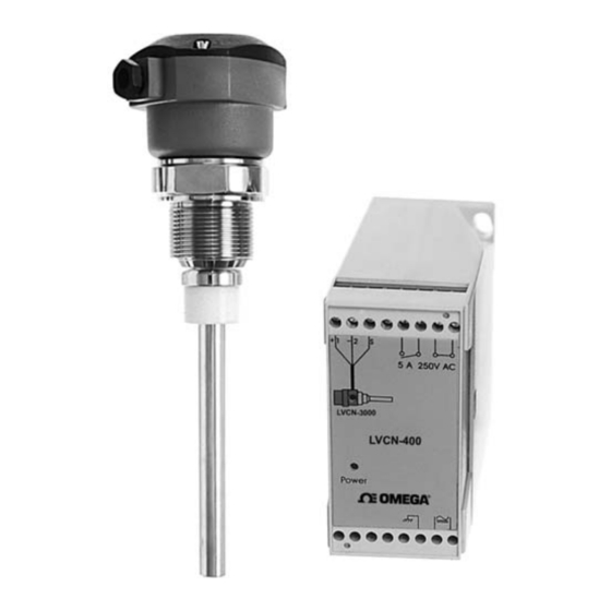
Made of 316 Stainless Steel, the LVCN4300 is available with various types of process connections such as threaded, flange or sanitary. Custom connections available upon request. The LVCN400 Series can be ordered for varying supply voltages; 24Vdc ( LVCN401) , 110Vac... -
Page 5: Models & Dimensions
89mm 89mm 80mm Extended Necks for High Temperature Extended necks for medium temperature (up to 120°C) and high temperature (up to 150°C) LVCN4300 Standard LVCN400 Series Relay Controllers 111mm 1”NPT 5 a 250 V AC LVCN401 ½” Power ® L= Insertion length Note: Insertion Lengths greater than 150mm will require the balance to be ordered with a non-active portion of that insertion length. -
Page 6: Wiring Diagram
® Wiring Diagram LVCN4300- Nylon Housing (L1) LED: Indicates Level Detection (P1) Sensitivity Adjustment LVCN4300 ® Sens. 1- Positive 2- Negative Connection to the LVCN400 Controller 3- Out LVCN4300 - Aluminum Housing (L1) LED: Indicates Level Detection (P1) Sensitivity Adjustment ®... - Page 7 Wiring Diagram LVCN400 Series Relay Controller Note: The LVCN4300 series works in conjuction with the LVCN400 Relay controller and will not work without it. LVCN4300 Probe & LVCN401 Controller 1 2 3 Shielded (L2) 5 a 250 V AC (L3)
-
Page 8: Installation
To avoid radio frquency interference and possible malfunction, keep hand held communication equipment away from the LVCN4300 and LVCN400 Series. If this unavoidable make a metal shield around the the level switch and confirm that the unit has been properly grounded. - Page 9 (Fig. 2 correct Fig. 4 incorrect) Fig. 5 Ensure that the conduit is facing downward so that water does not enter the housing from the cable entry point. (Fig. 5) www.omega.com e-mail: info@omega.com...
-
Page 10: Calibration
® Calibration Calibration 1. Install the probe and power it on. The green Fig.1 LED (L3) on the controller should be on. LVCN4300 2.Turn the potentiometer (P1) counter-clockwise (Fig.1) before the tank is filled. Sens. ® 4.Fill the tank until the probe is in contact with the medium. -
Page 11: Handling
Care should be taken when handling and installing probes with coated rods to avoid scratching them. Scratching the coating could interfere with the probe performance. Fig. 5 When cleaning the rod use a soft brush or rag. www.omega.com e-mail: info@omega.com... -
Page 12: Technical Specifications
® Technical Specification LVCN4300 + LVCN400 Series 5 a 250 V AC ® 1 2 3 LVCN4300 LVCN4300 ® LVCN401 Sens. Sens. Power ® Nylon housing Aluminum housing LVCN400 - Controller Application Level Detection for Solids and liquids. LVCN401: 24Vdc (+/- 10%) -
Page 13: Trouble Shooting
Relay does not Verify the connections LVCN400 work Adjust sensitivity with Low sensitivity the potentiometer Coating on the rod Consult for repair or Relay does not is damaged replacement turn off Clear the rod Material Build-up on the rod www.omega.com e-mail: info@omega.com... - Page 15 M-3995/0912...
Need help?
Do you have a question about the LVCN400 Series and is the answer not in the manual?
Questions and answers