Esse-ti 4G.VoLTE User Manual
Hide thumbs
Also See for 4G.VoLTE:
- User manual (48 pages) ,
- Quick installation manual (4 pages) ,
- User manual (44 pages)
Table of Contents
Advertisement
Advertisement
Table of Contents

Related Manuals for Esse-ti 4G.VoLTE


Summary of Contents for Esse-ti 4G.VoLTE
- Page 1 User’s manual 27/04/2021 7IS-80490...
-
Page 2: Table Of Contents
TABLE OF CONTENTS GENERAL INSTALLATION INSTRUCTIONS ......4 General Notes ................. 4 Making the installation ..............4 DESCRIPTION .................. 5 Features ....................6 LED ......................7 Hardware description ................8 INSTALLATION ................9 Inserting the SIM card ................9 Inserting the antenna ................9 Connection to the telephone line ............ - Page 3 Relay use ..................33 Activation/Deactivation ................. 33 Pulse ....................... 33 Reading advanced device and radio cell parameters ....34 SMS / E-MAILS THROUGH DB-9 ..........35 Sending SMS ..................36 Receiving SMS ..................37 Sending e-mails ..................37 DATA TRANSMISSION ..............39 FEMALE DB-9 CONNECTOR ............
-
Page 4: General Installation Instructions
The product must be EXCLUSIVELY used for the purpose it was designed for. Esse-ti shall not be responsible for damages arising from improper use. The product has been designed in compliance with the regulations in force and must be installed in systems that comply with the provisions of law. -
Page 5: Description
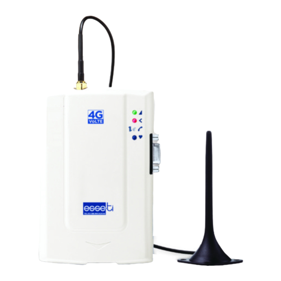
DESCRIPTION 4G.VoLTE 4G.VoLTE is a device that, connected to a fixed telephone or to the PSTN input terminals of a PABX or autodialer, allows you to make and receive calls over the 4G LTE/UMTS/GSM network. 4G.VoLTE gateway comes with built-in backup batteries and a relay output which can be activated either locally or remotely via SMS. -
Page 6: Features
Remote reboot function Data transmission from devices connected to the DB-9 connector in RS-232, RS-485 or CAN-bus standards (4G.VoLTE CAN only) SMS sending from devices connected to the DB-9 connector in RS- 232, RS-485 or CAN-bus standards (4G.VoLTE CAN only) ... -
Page 7: Led
230 Vac external adapter input 12 Vdc power supply input NiMH 800 mAh 7,2 V back up battery Female DB-9 connector (4G.VoLTE CAN only) Relay output External antenna (cable length = 2 m) External adapter (230 Vac 50 Hz input; 12 Vdc 500 mA output; CE mark) The gateway is equipped with 4 outer LEDs. -
Page 8: Hardware Description
LED indicating signal strength (green), LED indicating device operation status (red), LED indicating line status / data transmission (white) and LED indicating power supply status (blue) Female DB-9 connector (4G.VoLTE CAN only) RS-485 termination jumper (4G.VoLTE CAN only) CAN-bus termination jumper (4G.VoLTE CAN only) -
Page 9: Installation
INSTALLATION Inserting the SIM card Before inserting or replacing the SIM card, always make sure that the gateway has been disconnected from the mains and that no electrostatic discharge is present in order to avoid damaging it. Take all necessary measures to avoid electrostatic discharge. Shift the SIM card housing cover downward until it unblocks and ... -
Page 10: Connection To The Telephone Line
Position the antenna with magnetic base so that any metal surfaces do not block the signal. Connection to the telephone line Connect the gateway to a standard telephone or to the PSTN input terminals of a PABX or autodialer via the RJ-11 connector (G in the picture at page 8). -
Page 11: Connection To The Power Supply
Connection to the power supply Power supply via 230 Vac external adapter Connect the external adapter to the specific input (H in the picture at page 8). Connect the backup batteries to the dedicated input (N in the picture at page 8). -
Page 12: Turning The Gateway On
Turning the gateway on Power the gateway. Wait 30 seconds after power-up to give time to the gateway to register correctly with the 4G LTE/UMTS/GSM network. Make sure the red LED (device status) flashes as shown in chapter ... -
Page 13: Gateway Mounting Operations
Gateway mounting operations Check the 4G LTE/UMTS/GSM signal strength through the green indicator LED (see chapter “Signals”, page 44) and identify an area where the signal is strong enough. Note: the signal strength may vary according to the telephone provider. Drill two holes with 5 mm diameter on the wall at a distance of 50 ... -
Page 14: Installation Recommendations
Installation recommendations The gateway must be installed in a location where the radio signal allows for using the system. 4G LTE/UMTS/GSM It is advisable to leave plenty of space around the gateway for maintenance operations. Do not install the gateway outdoors, since it lacks protection devices against weather conditions that can damage the gateway (water, humidity, etc.). -
Page 15: Programming
PROGRAMMING Programming can be carried out locally via a multi-frequency telephone or remotely via SMS. ROGRAMMING BY TELEPHONE Connect a standard telephone to the gateway via the RJ-11 connector (G in the picture at page 8) or using the TEL terminals (I in the picture at page 8). - Page 16 COUNTRY SETTING Default: automatic country setting X: option, from 1 to 2 1= mobile network line tones 2= line tones generated by 4G.VoLTE LINE TONES **2X# (recommended for autodialers or other devices effecting tone detection over the line) INTER-DIGIT X: seconds, from 1 to 9;...
- Page 17 PROGRAMMING BY TELEPHONE **5*1# Enabling Disabling XXX: MCC of your telephone operator Y…Y: MNC of your telephone operator ROAMING **5*0*XXXY...Y# (when roaming is disabled, in case the gateway registers with a different provider than the programmed, it is not possible to make or receive any calls) Default: roaming enabled X…X: telephone number appointed for SMS...
- Page 18 PROGRAMMING BY TELEPHONE X: option, from 0 to 1 **5X# 0= check enabled 1= check disabled X: option, from 0 to 7 0= 7 h 1= 6 h e 30’ 2= 6 h BATTERY 3= 5 h e 30’ CHECK 4= 4 h **52*X# 5= 2 h e 30’...
- Page 19 PROGRAMMING BY TELEPHONE X: option, from 0 to 6 0= notifications disabled 1= the relay is deactivated in case of external power failure 2= the relay is deactivated in case of mobile RELAY-BASED network loss NOTIFICATION 3= the relay is deactivated in case of OF EXTERNAL external power failure or in case of POWER FAILURE...
- Page 20 PROGRAMMING BY TELEPHONE ENTERING NUMBER TO CALL **26*X…X*Y*Z… X…X: programming password Z*Z…Z# Y: table position, from 1 to 6 Z…Z: telephone number DELETING NUMBER TO CALL **26*X…X*Y# X…X: programming password Y: table position, from 1 to 6 DELETING ALL NUMBERS TO CALL AUTOMATIC **26*X…X*# X…X: programming password...
- Page 21 PROGRAMMING BY TELEPHONE X: option, from 0 to 128 0= all codecs enabled 1= FR enabled 2= EFR enabled VOICE CALLS 4= HR enabled **15*X…X# CODEC SETTING 8= AMR-FR enabled 16= AMR-HR enabled 32= GSM-AMR-WB enabled 64= UMTS-AMR-NB enabled 128= UMTS-AMR-WB enabled X…X: AMR-WB mode (configurable as a bitmask: 0x1 - Mode 0 (6.60 kbps)
-
Page 22: Sim Card Expiration Check
PROGRAMMING BY TELEPHONE X: option, from 0 to 6 0= GSM 1= GSM / UMTS COMMUNICATION 2= UMTS TECHNOLOGY **33*X# 3= LTE SETTING 4= UMTS / LTE 5= GSM / LTE 6= GSM / UMTS / LTE Restoring factory default does not modify the RESTORING programming password and the settings DEFAULT... -
Page 23: External Power Failure Control
If the battery check is enabled, the gateway detects the presence of the battery. If the battery is absent or in case of disconnection, a notification SMS is sent to the programmed number with the following text message: “Dead battery”. External power failure control If the control on external power failure is enabled, the gateway constantly controls the external power supply (230 Vac or 12 Vdc). -
Page 24: Automatic Converter Of Selected Telephone Number
Note: the internal clock must be programmed each time the device is switched off. Automatic converter of selected telephone number If the function is enabled the gateway, instead of calling the telephone number dialed from the connected telephone (autodialer or other telephone device), forwards the call to a previously set number. - Page 25 telephone number included in the “Preset telephone number” column. Matching telephone numbers automatically Enter the number to be called in a table location using programming code 26. Enter the dialed number, to be associated, in the same table location using programming code 25.
-
Page 26: Programming Via Sms
ROGRAMMING VIA Programming via SMS is possible by any mobile phone or other device supporting SMS. In case the administrator number has been previously set, programming via SMS is only allowed from such telephone number. An SMS notifying that programming has been completed will be sent back by the gateway to the same telephone number that forwarded the programming SMS. - Page 27 Programming Code (x..x) Enabling CLIP 7*1*DDMMYY*HHMM Disabling CLIP Reading CLIP status CLIR permanent setting Reading CLIR permanent status CLIR temporary activation CLIR temporary deactivation Enabling roaming service Disabling roaming service 5*0*XXXY…Y Reading roaming service status Setting telephone number for notification service 40*X…X*X…X Deleting notification number Reading notification number...
- Page 28 Programming Code (x..x) Reading time of periodic test Duration of CLI call 76*XX Reading duration of CLI call Enabling periodic test 77*1 Disabling periodic test 77*0 Forcing periodic test 77*2 Reading periodic test status Entering preset number 26*X…X*Y*Z…Z*Z…Z Deleting preset number 26*X…X*Y Deleting all preset numbers 26*X…X*...
-
Page 29: Notification Message Format
Example: it is required to enable battery check and to set the telephone number for notifications. Outgoing message text: ET-IL2*0#50#40*X..X*X…X# Notification message format The format of the message notifying the user or the administrator who previously sent out a programming SMS, is the same as the programming message format. -
Page 30: Services
SERVICES NCOMING CALLS Allows you to answer incoming calls. Upon receiving a phone call, the LED indicating the line status (white) will blink shortly 4 times every 4 seconds as described at chapter “Signals” (see page 45) and the telephone will be ringing. Pick up the handset to answer the call. -
Page 31: Measuring The Signal Level
EASURING THE SIGNAL LEVEL This procedure allows you to check the 4G LTE/UMTS/GSM signal level through your telephone. Lift the handset and dial **30#. Wait for the signal reading. The gateway will send a number of short tones corresponding to the signal level: Tones Quality... -
Page 32: Reading The Days Missing To Sim Card Expiration
EADING THE DAYS MISSING TO CARD EXPIRATION This procedure allows you to check how many days until the SIM card expiration. Lift the handset and dial **54#. After the confirmation tone hang up. After receiving the request, the gateway will send an SMS to the number programmed to be alerted. -
Page 33: Relay Use
ELAY USE This programming only applies when the relay is not used to signal the external power supply and/or 4G LTE/UMTS/GSM network failure. Activation/Deactivation Allows you to activate or deactivate the relay. Lift the handset and dial: **92*. Enter: ... -
Page 34: Reading Advanced Device And Radio Cell Parameters
ET-IL2*xxx#90# where: ET-IL2 programming string start *xxx# password string (default xxx = 0) 4G.VoLTE will send one or two SMS to the number that sent the request with the following data: String Meaning (the values shown are for illustrative purposes) -
Page 35: Sms / E-Mails Through Db-9
SMS / E-MAILS THROUGH DB-9 4G.VoLTE CAN gateways allow devices connected to the DB-9 connector (in standard RS-232, RS-485 or CAN-bus) to send or receive SMS and to send e-mails. DB-9 PROGRAMMING X: option, from 0 to 3 0= communication disabled... -
Page 36: Sending Sms
Sending SMS Text messages transmitted from an external device to the 4G.VoLTE CAN, through the DB-9 connector, are sent via SMS when they comply with the following format: ES^SMSX…X:Y…Y<CTRL+Z> where: ES^SMS string start X...X telephone number on which the SMS must be sent Y...Y... -
Page 37: Receiving Sms
SMS received <CTRL+Z> non-editable character defining end of text Sending e-mails A text transmitted from an external device to the 4G.VoLTE CAN, through the DB-9 connector, is sent via e-mail when it complies with the following format: ES^MAILX…X<CTRL+Z>Y…Y<CTRL+Z>Z…Z<CTRL+Z>... - Page 38 ET-IL2*xxx#62*n...n*n…n#Cy...y#Fw...w#Gz...z#13*u# where: ET-IL2 programming string start *xxx# password string (default xxx = 0) n...n telephone number of the SIM card in 4G.VoLTE CAN (with country code) y…y w…w APN username (if any) z…z APN password (if any) COMNet Server connection mode...
-
Page 39: Data Transmission
DATA TRANSMISSION The COMNet system allows users to connect remotely with devices equipped with RS232/RS485/CAN BUS, replacing traditional serial communication which is commonly performed locally (i.e. between peripherals and custom boards – Fig. A – or between a PC-based proprietary application and a lift controller board – Fig. B –). Figure A: example of local serial communication Figure B: example of local serial communication Figure C: general example of remote serial communication... - Page 40 Setting up a COMNet system requires: - connecting a 4G.VoLTE CAN gateway (properly programmed) to the serial port of the remote device to be controlled (the SIM card to be inserted into the gateway must be enabled for voice/SMS/data traffic)
- Page 41 SIM card needed for remote monitoring. 4G.VoLTE CAN can manage a data call and a voice call at the same time, therefore in case of a voice emergency call, the ongoing data connection will not be cut off.
-
Page 42: Female Db-9 Connector
FEMALE DB-9 CONNECTOR RS-232 PIN2 PIN3 PIN5 RS-485 TXD- PIN6 TXD+ PIN7 PIN5 CAN-bus CANH PIN8 CANL PIN9 PIN5 Page 42... -
Page 43: Signals
SIGNALS ONES Dialling It indicates that the gateway is ready for dialing. Dissuasion It indicates that t he gateway has not properly registered with the 4G delay in dialling or the end of conversation or LTE/UMTS/GSM provider or a an access to services not permitted. Busy It indicates that the called party is busy. -
Page 44: Call Signals
It indicates good signal level. It indicates high signal level. It indicates no signal. ALL SIGNALS It indicates an incoming call. 4G LTE/UMTS/GSM signal indicator LED (GREEN) It indicates no signal. It indicates low signal level. It indicates medium signal level. It indicates good signal level. -
Page 45: Status Indicator Led (Red)
It indicates the SIM card is protected by the PIN code. It indicates the SIM card is protected by the PUK code. Status indicator LED (RED) It indicates the gateway has not been correctly registered with the network, the SIM card is protected by the PIN code or other problems. It indicates the gateway is correctly registered to the network. - Page 46 It indicates that the line is not in use and the gateway is registered to a 4G network with high signal level. It indicates an incoming call. Page 46...
-
Page 47: Power Supply Status Indicator Led (Blue)
Power supply status indicator LED (BLUE) It indicates that the external power supply is connected and the battery guarantees more than 7-hour operation in idle state. It indicates that the external power supply is connected and the battery guarantees up to 7-hour operation in idle state. It indicates that the external power supply is connected and the battery guarantees 2-hour operation in idle state. -
Page 48: Problem-Detection Guide
The autodialer The autodialer performs Set line tone generation by connected to gateway a tone detection over the 4G.VoLTE (see programming does not succeed in telephone line “Line tones” option 2 ) forwarding a call Page 48... -
Page 49: Eu Declaration Of Conformity
EU DECLARATION OF CONFORMITY Hereby, Esse-ti S.r.l. declares that the equipment type 4G.VoLTE is in compliance with Directive 2014/53/EU. The full text of the EU declaration of conformity is available from the following Internet address: https://www.esse-ti.it/en/dichiarazioni-di-conformita Page 49... - Page 50 Page 50...
- Page 51 Page 51...
- Page 52 Esse-ti s.r.l. via G. Capodaglio, 9 62019 Recanati (MC), ITALY tel. +39 071 7506066 fax +39 071 7506057 support@esse-ti.it www.esse-ti.it...
Need help?
Do you have a question about the 4G.VoLTE and is the answer not in the manual?
Questions and answers
how to get out of proactive texting
To disable proactive texting (data notifications) on the Esse-ti 4G.VoLTE, send the following programming code:
**02*0#
This command disables data notifications.
This answer is automatically generated