Advertisement
Quick Links
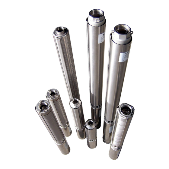
4 Inch (100mm) Submersible Pumps
Installation and
Operation Manual
"SC" Series All Stainless Steel
"SD" Composite/Stainless Steel
General Information and Precautions
Submersible pumps are precision equipment designed for years of
trouble free service, provided that they are properly installed and maintained.
The pump package includes pump, motor, motor tail lead, and cable splicing
kit on all units. A control box (which contains the start capacitor(s) and thermal
overload relay) is shipped as standard equipment on all three wire, single phase
units. The two wire, single phase units do not require a control box as the start
capacitor and thermal overload is built into the motor. Magnetic starters, equipped
with the correct quick trip thermal overloads, are required for three phase units.
Properly grounded lightning arrestors are recommended on all installations that
do not have built-in lightning protection in the motor.
WARNINGS:
1.
working in accordance with National and Local Electrical Codes. Failure
to comply with these codes could result in serious injury or death from
electrical shock, or cause serious damage to the pump unit.
2. The bore must be clean and straight. Submersible pumps are designed
to allow the passage of a small amount of sand; however, pumping sand
for a prolonged period will shorten the life of any pump.
3. The pump should be installed at least 3 metres (10 feet) above the
bottom of the bore to prevent sediment from covering the motor, which
could result in overheating and damage to the motor windings. Where
possible, the pump should be installed at least 4.5 metres (15 feet)
below the lowest pumping water level. A motor cooling shroud is
recommended.
4. Never support the weight of the pump on the electrical cable. Support
it with the rising main or an auxiliary rope during installation. Throughout
installation, take care not to damage the insulation on the cable.
Instructions for Coupling Pump End Assembly to Motor
shaft protrusion. To assemble the pump and motor:
1. Make sure that the pump and motor rotors rotate freely.
2. Carefully clean the surfaces to be joined.
3. For motors with separate leads clean and dry any moisture from both the cavity on the motor and the rubber end
of the electrical cable connection. Insert the cable connection (using no lubrication) and tighten with a torque wrench
set at 27Nm (20 ft.lbs).
4. Align cable with cable protector and push the motor lead through the suction inlet and under the cable guard. Do
not slacken nuts on pump straps (all stainless steel SC Series units).
5. Couple the pump to the motor making sure that the motor shaft freely enters the splined slot on pump coupling.
A layer of waterproof grease should be applied to the coupling splines to help with this operation and to protect
against wear caused by any abrasive particles remaining.
6. Tighten the four motor bolts with a torque wrench set at 18Nm (14 ft.lbs).
Pre-Installation Tests
Complete as many pr e-installation tests as possible prior to taking the pump to the installation site.
1.
Be car eful not to damage the motor, pump, and motor lead. Visually inspect for possible damage. Check the lead
for abrasions or cuts. Make certain the check valve operates freely.
2.
Check the motor, pump, and control equipment to be certain they are matched. If using a three phase motor, check
quick trip thermal overloads in the magnetic starter against motor requir
3. Mount the pump end on the motor, if needed (see previous section). Splice the cable to the furnished lead with
the supplied splice kit, following the splice kit instructions. Use only the size cable recommended in the Cable
Selection Table (Page 6) to assure adequate voltage at the motor.
IMPORTANT
For future reference, record details
of your pump unit here.
Date installed ....../ ....../ ......
Submersible Pump
Model: ......................
Serial No: .................
Q. ...... m
/hr
3
(@BEP)
H. ............ m
(@BEP)
P. ......... kW
RPM ............
A division of Pentair Flow Control
(if not assembled)
........... Hz
Max H .......... m
Pty Ltd
Page 1
Advertisement

Related Manuals for Pentair SC Series


Summary of Contents for Pentair SC Series
- Page 1 4. Align cable with cable protector and push the motor lead through the suction inlet and under the cable guard. Do not slacken nuts on pump straps (all stainless steel SC Series units). 5. Couple the pump to the motor making sure that the motor shaft freely enters the splined slot on pump coupling.
- Page 2 “SC/SD” SERIES 4 Inch Submersible Pump Installation and Operation Manual Remove cover fr om control box on magnetic starter. Do not connect line voltage at this time. Connect cable to control box. Make certain each lead is connected to the proper terminal as indicated in the instruction on the control box (also refer to the section on Wiring the Pump).
- Page 3 “SC/SD” SERIES 4 Inch Submersible Pump Installation and Operation Manual All electrical connections must Wiring the Pump - Single Phase be performed by quali ed personnel working in accor dance with National and a. Three wire installation for FRANKLIN 0.75kW motor and 1.5kW PSC motor. Local Electrical Codes.
- Page 4 “SC/SD” SERIES 4 Inch Submersible Pump Installation and Operation Manual Wiring the Pump - Single Phase All electrical connections must be performed by quali ed e. Thr ee wire installation for COVERCO 0.37kW, 0.55kW, 0.75kW, personnel working in 1.1kW, 1.5kW, 2.2kW, and 3.7kW motors. (CURRENT MODELS) accor dance with National and Local Electrical Codes.
-
Page 5: Lightning Arrestors
“SC/SD” SERIES 4 Inch Submersible Pump Installation and Operation Manual All electrical connections must be performed by quali ed personnel working in accor dance with National and Local Electrical Codes. MAINS L1 L2 ISOLATION SWITCH OR a: Dischar ge method - Connect the leads to the CIRCUIT magnetic starter as in Step 2. - Page 6 “SC/SD” SERIES 4 Inch Submersible Pump Installation and Operation Manual CABLE SELECTION FRANKLIN OVERLOAD PROTECTION MOTOR DA TA CABLE SELECTION 4 INCH FRANKLIN SUBMERSIBLE MOTORS SINGLE PHASE MOTOR - Maximum cable length metres (Motor to service entrance). 2 Wire motors - Cable spec – 2 core with earth, P.V.C. insulated, P.V.C. sheathed, copper conductors. CABLE SIZE SQ.MM Motor kW F.L.A.
- Page 7 “SC/SD” SERIES 4 Inch Submersible Pump Installation and Operation Manual CABLE SELECTION COVERCO OVERLOAD PROTECTION MOTOR DA TA CABLE SELECTION 4 INCH COVERCO SUBMERSIBLE MOTORS SINGLE PHASE MOTOR - Maximum cable length metres (Motor to service entrance) 3 Wire motors - Cable spec – 3 core with earth, P.V.C. insulated, P.V.C. sheathed, copper conductors. CABLE SIZE SQ.MM Motor kW F.L.A.
- Page 8 “SC/SD” SERIES 4 Inch Submersible Pump Installation and Operation Manual MOTOR COOLING The following graph shows the minimum required water ow past motor for cooling. For example a 100mm (4") Franklin motor and pump installed in 200mm inside diameter bor e casing requires a minimum ow past the motor of 1.9 litres per second.
-
Page 9: Troubleshooting Chart
4. Water logged tank. Clean or replace air volume control. Drain and recharge tank. If none of the above remedies the problem please contact your local Southern Cross Dealer or call Pentair Southern Cross on 131 786 WARNINGS & SPECIFICATIONS... - Page 10 “SC/SD” SERIES 4 Inch Submersible Pump Installation and Operation Manual Telephone 131 786 www.southerncross.pentair.com A division of Pentair Flow Control Pacific Pty Ltd A.B.N. 83 000 922 690 Page 10...
Need help?
Do you have a question about the SC Series and is the answer not in the manual?
Questions and answers