
Related Manuals for Schmalz SCTMc


Summary of Contents for Schmalz SCTMc
- Page 1 Mini Compact Terminal SCTMc Operating Instructions WWW.SCHMALZ.COM EN-US · 30.30.01.02041 · 01 · 02/21...
- Page 2 Published by © J. Schmalz GmbH, 02/21 This document is protected by copyright. J. Schmalz GmbH retains the rights established thereby. Repro- duction of the contents, in full or in part, is only permitted within the limits of the legal provisions of copyright law. Any modifications to or abridgments of the document are prohibited without explicit writ- ten agreement from J. Schmalz GmbH.
-
Page 3: Table Of Contents
Contents Contents 1 Important Information ........................... 5 Note on Using this Document ...................... 5 The technical documentation is part of the product ................ 5 Type Plate ............................ 5 1.3.1 Compact Ejector........................... 5 1.3.2 Mini Compact Terminal....................... 6 Warnings in This Document........................ 6 Symbol.............................. - Page 4 Contents Installation ............................ 20 Pneumatic Connection ........................ 20 8.3.1 Connecting the Compressed Air and Vacuum ................. 21 8.3.2 Instructions for the Pneumatic Connection ................ 21 Electrical Connection......................... 22 8.4.1 Pin assignments ......................... 23 9 Operation .............................. 24 General Preparations ........................ 24 10 Troubleshooting............................ 25 10.1 Help with Malfunctions ........................
-
Page 5: Important Information
ð Failure to follow the instructions in these Operating instructions may result in injuries! ð Schmalz is not liable for damage or malfunctions that result from failure to heed these instructions. If you still have questions after reading the technical documentation, contact Schmalz Service at: www.schmalz.com/services... -
Page 6: Mini Compact Terminal
Important Information 1.3.2 Mini Compact Terminal The type plate (1) is permanently attached to the product and must always be clearly legible. The type plate (1) contains the following data: • Designation, incl. individual configuration codes (terminal “XY”, ejector “AAA”) • Permitted pressure range •... -
Page 7: Fundamental Safety Instructions
Fundamental Safety Instructions 2 Fundamental Safety Instructions 2.1 Safety The ejector emits noise due to its use of compressed air. WARNING Noise pollution due to the escape of compressed air Hearing damage! 4 Wear ear protectors. 4 The ejector must only be operated with a silencer. WARNING Uncontrolled movements of system components or falling of objects caused by in- correct activation and switching of the Ejector while persons are in the plant... -
Page 8: Non-Intended Use
2.5 Modifications to the Product Schmalz assumes no liability for consequences of modifications over which it has no control: 1. The product must be operated only in its original condition as delivered. 2. Use only original spare parts from Schmalz. -
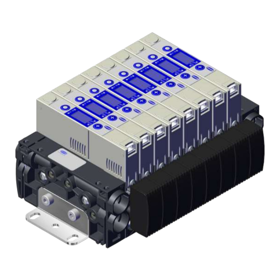
Page 9: Product Description
3.1 Mini compact terminal description The Schmalz mini compact terminal SCTMc, or SCTMc for short, is a compact unit of multiple vacuum gen- erators known as ejectors. Thanks to its modular design, up to 16 individual ejectors can be controlled and configured independently. -
Page 10: Components Of The Mini Compact Terminal
— — 3.4 Description of the Ejector Every SCTMc mini compact ejector has an electrical connection to the voltage supply and to communica- tion with the control for the superordinate machine. The compressed air supply is connected centrally for all ejectors. -
Page 11: Depositing The Workpiece/Part (Blowing Off)
Product Description The venturi nozzle on the ejector is activated and deactivated using the suction command: • In the NO (normally open) variant, the venturi nozzle is deactivated when the suction signal is re- ceived. • In the NC (normally closed) variant, the venturi nozzle is activated when the suction signal is re- ceived. -
Page 12: Ejector Structure
Product Description 3.6 Ejector Structure Vacuum connection (marking 2) Operating and display elements Electrical connector, JST plug, 5-pole Exhaust air collector (marking 3) Valve screw for blow off volume flow Mounting holes 2x Input to compressed air channel — — 3.7 Controls and Displays in Detail The ejector is fitted with the following elements to ensure simple operation: •... - Page 13 Product Description Definition of the LED indicators The “suction” and “blow off” process states are each assigned an LED. Item Meaning Status Description Blow off LED B Ejector not blowing off Ejector blowing off lit up Suction LED S No suction from ejector Suction from ejector lit up The LEDs for the switching points SP1 and SP2 (limit values) indicate the current level of the system vac-...
-
Page 14: Technical Data
Technical Data 4 Technical Data 4.1 Display Parameters Parameter Value Unit Note Display Digit Red 7-segment LED display Resolution ±1 mbar Accuracy ±3 % FS = 25°C, based on FS final value (full-scale) Display refresh rate Only affects the 7-segment display Idle time before the The display mode is accessed automatically when no set- menu is exited tings are made in a menu. -
Page 15: Performance Data
Technical Data 4.4 Performance Data Type Nozzle 07 Nozzle 10 Nozzle size [mm] Degree of evacuation [%] Max. suction rate [l/min] Air consumption for suction [l/min] Air consumption for blow off [l/min] Sound pressure level, unobstructed suction [dB(A)] Sound pressure level, suction [dB(A)] Pressure range [bar] 3...6 Rec. -
Page 16: Dimensions
Technical Data 4.6 Dimensions 165.4 185.2 12.5 66.8 31.5 83.3 42.9 32.5 170.8 167.8 All specifications are in mm. 4.7 Factory Settings Code Parameter Value of the factory setting Switching point SP1 750 mbar Reset point rP1 600 mbar Switching point SP2 550 mbar Reset point rP2 540 mbar Vacuum unit in mbar = bar Vacuum unit... -
Page 17: Operating And Menu Concept
Operating and Menu Concept 5 Operating and Menu Concept The ejector is operated using two buttons on the foil keypad: MENU BUTTON PLUS BUTTON The following information can be shown on the display: • The current vacuum measurement value • The settings •... -
Page 18: Description Of Functions
Description of Functions 6 Description of Functions 6.1 Analog output The integrated sensor measures the vacuum and proportionally outputs an electrical voltage between 0 and 10 V at the analog output (OUT, PIN 4). 0 V corresponds to a vacuum of 0 mbar. 6.2 Displaying the software version The software version indicates the software currently running on the internal controller. -
Page 19: Transport And Storage
1. Compare the entire delivery with the supplied delivery notes to make sure nothing is missing. 2. Damage caused by defective packaging or occurring in transit must be reported immediately to the carrier and J. Schmalz GmbH. EN-US · 30.30.01.02041 · 01 · 02/21... -
Page 20: Installation
Installation 8 Installation 8.1 Installation Instructions CAUTION Improper installation or maintenance Personal injury or damage to property 4 During installation and maintenance, make sure that the ejector is disconnected and depressurized and that it cannot be switched on again without authorization. For safe installation, the following instructions must be observed: 1. -
Page 21: Connecting The Compressed Air And Vacuum
Installation CAUTION Noise pollution due to incorrect installation of the pressure and vacuum connec- tions Hearing damage 4 Correct installation. 4 Wear ear protectors. 8.3.1 Connecting the Compressed Air and Vacuum Compressed air connector (marking 1) 1x vacuum air connection per ejector disc (marking 2) The compressed air connector with the plug connector 10/8 is marked with the number 1 on the end plate. -
Page 22: Electrical Connection
Installation 3. Use only pipes or hoses with the recommended inner diameter to connect the ejector: Use hoses with sufficient internal diameter... Internal Ø Internal Ø for nozzle for nozzle size 0.7 mm size 1 mm on the vacuum side to avoid high flow resistance. 2 mm 4 mm If the internal diameter is too small, the flow resistance and the evacua-... -
Page 23: Pin Assignments
Installation 8.4.1 Pin assignments JST socket Symbol Function 24 V power supply “Suction” signal input Ground Analog output “Blow off” signal input EN-US · 30.30.01.02041 · 01 · 02/21 23 / 36... -
Page 24: Operation
Operation 9 Operation 9.1 General Preparations WARNING Extraction of hazardous media, liquids or bulk material Personal injury or damage to property! 4 Do not extract harmful media such as dust, oil mists, vapors, aerosols etc. 4 Do not extract aggressive gases or media such as acids, acid fumes, bases, biocides, dis- infectants or detergents. -
Page 25: Troubleshooting
Troubleshooting 10 Troubleshooting 10.1 Help with Malfunctions Malfunction Possible cause Solution 4 Make sure device is properly con- Power supply disrupted Electrical connection nected to power 4 Check electrical connection and pin No communication Incorrect electrical connection assignment 4 Check electrical connection and pin Ejector does not re- No power supply spond... -
Page 26: Maintenance
Maintenance 11 Maintenance 11.1 Safety Maintenance work may only be carried out by qualified personnel. WARNING Risk of injury due to incorrect maintenance or troubleshooting 4 Check the proper functioning of the product, especially the safety features, after every maintenance or troubleshooting operation. NOTE Incorrect maintenance work Damage to the ejector! - Page 27 Maintenance 2. To disconnect the disc elements and end plates, pull on the compressed-air distributors in the direction shown. Save the included O-rings. These should be handled with care and reused during mount- ing. 3. Place a small flat screwdriver on the new ejec- tor as shown and loosen the clamp.
- Page 28 Maintenance 5. Then remove the silencer from the ejector. 6. Remove the exhaust air collector on the ejec- tor to be replaced as shown above. 7. Insert it into the holder of the new ejector and fasten it with the clamp .
- Page 29 Maintenance 9. Check that the exhaust air collector is held tightly by pulling on the housing (hand-tight). ð The exhaust air collector is installed. 10. Place the ejector at the desired position in the terminal. Make sure that the O-rings are com- plete and in position.
-
Page 30: Replacing The Silencer
Maintenance 11.4 Replacing the Silencer When the silencer at the end of the exhaust air collector is open, a heavy infiltration of dust, oil, and so on, may contaminate it and reduce the suction capacity. We do not recommend cleaning the silencer be- cause of capillary action in the porous material. -
Page 31: Warranty
Warranty 12 Warranty This system is guaranteed in accordance with our general terms of trade and delivery. The same applies to spare parts, provided that these are original parts supplied by us. We are not liable for any damage resulting from the use of non-original spare parts or accessories. The exclusive use of original spare parts is a prerequisite for the proper functioning of the ejector and for the validity of the warranty. -
Page 32: Spare And Wearing Parts, Accessories
SCPMtc 10 6/4 NC JST-5 B86 O-Rings set, SCTMc-2-10 SEALING (100 x 10.07.08.00040) Center piece set incl. clamp, SCTMc-2-10 SD-M (5x 10.02.02.06030 + 5x 10.02.02.05894) SD element set + end piece incl. clamp (for SCTMc-2...8, 10.02.02.06002 + 10.02.02.06032 + 2x 10.02.02.05894) -
Page 33: Decommissioning And Recycling
Decommissioning and Recycling 14 Decommissioning and Recycling 14.1 Disposing of the Ejector 1. Dispose of the product properly after replacement or decommissioning. 2. Observe the country-specific guidelines and legal obligations for waste prevention and disposal. 14.2 Materials Used Component Material Housing PA6-GF Inner components Aluminum alloy, anodized aluminum alloy, stainless steel, POM Controller housing PC/ABS... -
Page 34: Attachment
Displays the software version Lock Menu locked 15.2 EC Declaration of Conformity EC Declaration of Conformity The manufacturer Schmalz confirms that the product SCTMi described in these operating instructions ful- fills the following applicable EC directives: 2006/42/EC Machinery Directive 2014/30/EU Electromagnetic Compatibility... - Page 35 30.30.01.02041 · 01 · 02/21 35 / 36...
Need help?
Do you have a question about the SCTMc and is the answer not in the manual?
Questions and answers