
Related Manuals for Schmalz SCTMi Series


Summary of Contents for Schmalz SCTMi Series
- Page 1 Schmalz Compact Terminal SCTMi (PROFINET, EtherNet/IP, EtherCAT) Operating Instructions WWW.SCHMALZ.COM EN-US · 30.30.01.01598 · 02 · 01/18...
- Page 2 Published by © J. Schmalz GmbH, 01/18 This document is protected by copyright. J. Schmalz GmbH retains the rights established thereby. Repro- duction of the contents, in full or in part, is only permitted within the limits of the legal provisions of copyright law. Any modifications to or abridgments of the document are prohibited without explicit writ- ten agreement from J. Schmalz GmbH.
-
Page 3: Table Of Contents
3.1 Description of the Compact Terminal .................... 10 3.2 Description of the Ejector ........................ 10 3.3 Variants and Type Key ......................... 11 3.4 Components of the Schmalz Compact Terminal SCTMi.............. 13 3.5 Bus Module Displays.......................... 13 3.6 Ejector Displays and Operating Elements ................... 17 4 Technical Data ............................... 18... - Page 4 Contents 5.2 Process Data............................ 23 5.2.1 Input Process Data ........................ 23 5.2.2 Output Process Data........................ 25 5.3 Parameter data............................. 27 5.4 Near Field Communication NFC...................... 47 6 Functions of the Compact Terminal and the Ejectors ................ 48 6.1 Overview of Functions ......................... 48 6.2 Device Data............................
- Page 5 Contents 7.2 Reusing the Packaging......................... 59 8 Installation.............................. 60 8.1 Installation Instructions........................ 60 8.2 Mounting .............................. 60 8.3 Instructions for the Pneumatic Connection .................. 61 8.4 Recommended Line Cross Sections (Internal Diameters) in mm ............ 61 8.5 Electrical Connection.......................... 62 8.6 Pin Assignments, L-coded M12 Connector for Voltage Supply ............ 63 8.7 Pin Assignments, D-coded M12 Socket for Industrial Ethernet............
-
Page 6: Important Information
3. Pass on the technical documentation to subsequent users. ð Schmalz is not liable for damage or malfunctions that result from failure to heed these instructions. If you still have questions after reading the technical documentation, contact the Customer Service Center www.schmalz.com/services... -
Page 7: Trademark
Important information 1.5 Trademark EtherCAT® is a registered trademark and patented technology, licensed by Beckhoff Automation GmbH, Germany. PROFINET® is a registered trademark of PROFIBUS and PROFINET International (PI). EtherNet/IP is a trademark of ODVA, Inc. EN-US · 30.30.01.01598 · 02 · 01/18 7 / 74... -
Page 8: Fundamental Safety Instructions
4 Do not extract aggressive gases or media such as acids, acid fumes, bases, biocides, dis- infectants or detergents. 4 Do not extract liquids or bulk materials, e.g. granulates. Schmalz accepts no liability for damages caused by non-intended usage of the SCTMi. In particular, the following are considered non-intended use: •... -
Page 9: Personnel Qualification
Fundamental Safety Instructions • Evacuation of objects that are in danger of imploding 2.5 Personnel Qualification Unqualified personnel cannot recognize dangers and are therefore exposed to higher risks! 1. Only instruct qualified personnel to perform the tasks described in this manual. 2. -
Page 10: Product Description
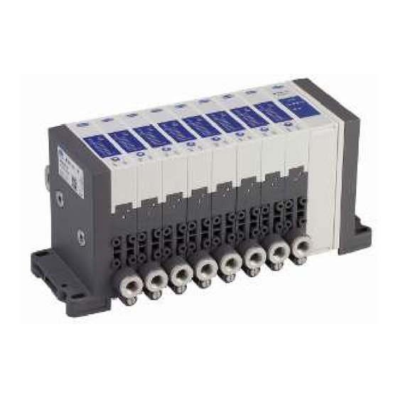
Example: SCTMi with 9 ejectors The Schmalz Compact Terminal SCTMi, or SCTMi for short, is a compact unit of multiple vacuum genera- tors known as ejectors. Thanks to its modular design, up to 16 individual ejectors can be controlled and configured independently. -
Page 11: Variants And Type Key
Product description Air saving function (diagram) Vacuum H1-h1 H2-h2 Time The ejector has an integrated air saving function and automatically regulates the vacuum in Suction mode: • The electronics switch the venturi nozzle off as soon as the set vacuum limit value (switching point H1) is reached. - Page 12 Product description Bus module variants Initials Bus module EtherNet/IP PROFINET EtherCAT The ejectors differ in nozzle size, pneumatic connection and the NO or NC variant. Codes for the different SCPSt ejector types: Code Type of ejector No ejector SCPSt 07 G02 NO SCPSt 10 G02 NO SCPSt 15 G02 NO SCPSt 07 G02 NC...
-
Page 13: Components Of The Schmalz Compact Terminal Sctmi
Product description 3.4 Components of the Schmalz Compact Terminal SCTMi Electrical connection: M12 connector for Electrical connection: M12-D socket for voltage supply (port X03) Ethernet (port X02) Electrical connection: M12-D socket for Bus module with display Ethernet (port X01) Ejector SCPSt (2 to 16 pcs.) - Page 14 Product description Bus module Meaning Status Description PROFINET Sensor volt- No sensor voltage Green Sensor voltage OK Flashing Sensor voltage not OK green Actuator No actuator voltage voltage Green Actuator voltage OK Flashing Actuator voltage not OK green Link port No PROFINET connection X01 and Green...
- Page 15 Product description Bus module Meaning Status Description EtherNet/IP Sensor volt- No sensor voltage Green Sensor voltage OK Flashing Sensor voltage not OK green Actuator No actuator voltage voltage Green Actuator voltage OK Flashing Actuator voltage not OK green Link port No EtherNet/IP connection X01 and Green...
- Page 16 Product description Bus module Meaning Status Description EtherCAT Sensor volt- No sensor voltage Green Sensor voltage OK Flashing Sensor voltage not OK green Actuator No actuator voltage voltage Green Actuator voltage OK Flashing Actuator voltage not OK green Link port No EtherCAT connection X01 and Green...
-
Page 17: Ejector Displays And Operating Elements
Product description 3.6 Ejector Displays and Operating Elements The MANUAL MODE button switches the ejector to manual mode. An LED bar and 4 LEDs are used to indicate the following information: Ejector Item Meaning Status Description Operating mode Green In operation Flashing green 1 Hz: Connection error 2 Hz: local firmware update... -
Page 18: Technical Data
Technical Data 4 Technical Data 4.1 Operation and Storage Conditions Operating medium Air or neutral gas 5 µm filtered Oiled or unoiled Class 3-3-3 compressed air quality acc. to ISO 8573-1 Operating pressure (flow pres- 2 to 6 bar (optimally 4 to 4.5 bar) sure) Working temperature 0 to 50 °C... -
Page 19: Mechanical Data
Technical Data 4.3 Mechanical Data 4.3.1 Performance Data All data is based on the ejector SCPSt: Type Nozzle size Max. vacuum Suction rate Blow-off air Air consump- l/min consumption tion l/min l/min SCPS-07 SCPS-10 SCPS-15 65.5 SCPS-2-07 SCPS-2-09 49.5 40.5 SCPS-2-14 71.5 at 4 bar Type Sound level... -
Page 20: Dimensions
Technical Data 4.3.2 Dimensions Type SCTMi (2) 89.2 123.2 18.5 97.5 13.5 SCTMi (3) 107.7 141.7 18.5 97.5 13.5 SCTMi (4) 126.2 160.2 18.5 97.5 13.5 SCTMi (5) 144.7 178.7 18.5 97.5 13.5 SCTMi (6) 163.2 197.2 18.5 97.5 13.5 SCTMi (7) 181.7 215.7 18.5... -
Page 21: Factory Settings
Technical Data Type m(g) SCTMi (2) 22.5 G1/8-IG G1/4-IG M12x1-AG SCTMi (3) 22.5 G1/8-IG G1/4-IG M12x1-AG SCTMi (4) 22.5 G1/8-IG G1/4-IG M12x1-AG 1120 SCTMi (5) 22.5 G1/8-IG G1/4-IG M12x1-AG 1330 SCTMi (6) 22.5 G1/8-IG G1/4-IG M12x1-AG 1540 SCTMi (7) 22.5 G1/8-IG G1/4-IG M12x1-AG... -
Page 22: Pneumatic Circuit Plans
Technical Data 4.3.4 Pneumatic circuit plans SCPSt...NO... SCPSt...NC... SCPSt 2...NO... SCPSt 2...NC... 22 / 74 EN-US · 30.30.01.01598 · 02 · 01/18... -
Page 23: Interfaces
Interfaces 5 Interfaces 5.1 Industrial Ethernet The industrial Ethernet interface is used to control the entire SCTMi, set all of the parameters and provide a wide variety of measurement and analysis data. The PROFINET, EtherNet/IP or EtherCAT protocol is supported, depending on the design. 5.2 Process Data The cyclical process data is used to control the ejectors and receive current information reported from the Compact Terminal SCTMi. - Page 24 Interfaces Errors in the Control Unit [ro] BYTE [1] Control Unit Error Bit 7 Bit 6 Bit 5 Bit 4 Bit 3 Bit 2 Bit 1 Bit 0 Bit 0 Internal error: data corruption Bit 1 Internal error: bus fault Bit 2 Primary voltage too low Bit 3...
-
Page 25: Output Process Data
Interfaces BYTE [5] (Ejectors 9 to 12) PP12 AS12 PP11 AS11 PP10 AS10 PP09 AS09 Bit 7 Bit 6 Bit 5 Bit 4 Bit 3 Bit 2 Bit 1 Bit 0 BYTE [6] (Ejectors 13 to 16) PP16 AS16 PP15 AS15 PP14 AS14... - Page 26 Interfaces EJECTOR CONTROL [rw] BYTE [1] (Ejectors 1 to 4) Bit 7 Bit 6 Bit 5 Bit 4 Bit 3 Bit 2 Bit 1 Bit 0 Bit 0 S01: Ejector #1 suction Bit 1 B01: Ejector #1 blow-off Bit 2 S02: Ejector #2 suction Bit 3...
-
Page 27: Parameter Data
Interfaces 5.3 Parameter data More precise information regarding the system status can also be retrieved using the acyclical communica- tion channel. All of the settings (e.g. control thresholds, switching points, permitted leakage, and so on) for the SCTMi can also be read or modified. You can access additional identifying information for the SCTMi, such as part number and serial number, and save user-specific information such as the installation or storage loca- tion. - Page 28 Interfaces Name Access Type Description Min. value Determined by at- Minimum value permitted tributes #2, #3 and #9 Default value Determined by at- Default parameter value tributes #2, #3 and #9 Number of sub- Array of UINT8 Number of sub-elements, default value is 1 elements Attribute 5 causes the values of the parameter data to be read or, if permission is granted, written as well.
- Page 29 Interfaces 0x00FC Production date char 0x00FD Installation date char 1 to 16 0x00FE System configuration uint8 Device Settings Offset Index Description Type Length [bytes] (Dec) (Hex) 0x0002 System command uint8 0x005A Extended device locks uint8 0x005B PIN code uint16 0x0064 0 to 15 Setpoint H1 for ejectors #1 to #16 uint16...
- Page 30 Interfaces Device Diagnostics Offset Index Description Type Length [bytes] (Dec) (Hex) 0x0082 0 to 15 Errors in ejectors #1 to #16 uint8 16 x 1 0x0082 Errors in the control unit uint8 0x008A Extended device status – event category uint16 0x008A Extended device status –...
- Page 31 Interfaces Product Name Parameter 18 (0x0012) Description Product name Index Data type char Length 32 bytes Access Read only Value range Default value Unit EEPROM Product Text Parameter 20 (0x0014) Description Product text Index Data type char Length 32 bytes Access Read only Value range...
- Page 32 Interfaces Value range Default value Unit EEPROM Firmware Revision Parameter 23 (0x0017) Description Firmware Revision Index Data type char Length 5 bytes Access Read only Value range Default value Unit EEPROM User ID Parameter 24 (0x0018) Description Application-specific tag Index Data type char Length...
- Page 33 Interfaces Device Features Parameter 241 (0x00F1) Description Device Features Index Data type uint8 Length 11 bytes Access Read only Value range Default value Unit EEPROM Device ID Parameter 242 (0x00F2) Description Equipment identification Index Data type char Length 64 bytes Access Read/Write Value range...
- Page 34 Web Link for NFC APP Parameter 248 (0x00F8) Description NFC web link Index Data type char Length 64 bytes Access Read/Write Value range Default value https://myproduct.schmalz.com/#/ Unit EEPROM Storage ID Parameter 249 (0x00F9) Description Storage location Index Data type char Length 32 bytes Access...
- Page 35 Interfaces Item Index Parameter 251 (0x00FB) Description Article revision Index Data type char Length 2 bytes Access Read only Value range Default value Unit EEPROM Manufacturing date Parameter 252 (0x00FC) Description Production date Index Data type char Length 10 bytes Access Read only Value range...
- Page 36 Interfaces Default value Unit EEPROM System Commands Parameter 2 (0x0002) Description System commands – triggers special features of the device Index Data type uint8 Length 1 bytes Access Write only Value range 0x82: Reset device parameters to factory defaults 0xA5: Calibrate vacuum sensors of all ejectors 0xA7: Reset erasable counters in all ejectors 0xA8: Reset voltage min./max.
- Page 37 Interfaces Default value Unit EEPROM Switching Point Setting H1 for the Ejectors Parameter 100 (0x0064) Description Setpoint H1 for ejectors Index Index 0 to 15 corresponds to ejector #1 to #16 Data type uint16 Length 32 bytes Access Read/Write Value range 998 >= H1 >= (H2+h1) Default value Unit...
- Page 38 Interfaces Hysteresis Setting h2 for the Ejectors Parameter 103 (0x0067) Description Hysteresis h2 for ejectors Index Index 0 to 15 corresponds to ejector #1 to #16 Data type uint16 Length 32 bytes Access Read/Write Value range (H2-2) >= h2 >= 10 Default value Unit mbar...
- Page 39 Interfaces Value range 0 to 999 Default value Unit mbar/s EEPROM Control Mode of the Ejectors Parameter 109 (0x006D) Description Control mode for ejectors Index Index 0 to 15 corresponds to ejector #1 to #16 Data type uint8 Length 16 bytes Access Read/Write Value range...
- Page 40 Interfaces Length 6 bytes Access Read only Value range Default value Unit 0.1 V EEPROM Power supply for actuator Parameter 67 (0x0043) Description Auxiliary supply voltage Index 0: actual value as measured by the device 1: min. value since last power-up 2: max.
- Page 41 Interfaces Air Consumption of the Ejectors Parameter 156 (0x009C) Description Air consumption per cycle for ejectors Index 0 to 15: Air consumption per cycle for ejectors #1 to #16 16: Air consumption per cycle of all ejectors Data type uint32 Length 68 bytes Access...
- Page 42 Interfaces Length 32 bytes Access Read only Value range 0 to 999 Default value Unit mbar EEPROM Vacuum Value of the Ejectors Parameter 515 (0x0203) Description System vacuum for ejectors Index Index 0 to 15 corresponds to ejector #1 to #16 Data type uint16 Length...
- Page 43 Interfaces Bit 6 = Supply pressure too low (<1.9 bar) or too high (>6.3 bar) Bit 7 = Error in one or more ejectors Default value Unit EEPROM Extended Device Status Event Category Parameter 138 (0x008A) Description Extended device status – event category Index 1: Event category of current device status Data type...
- Page 44 Interfaces 0x8D00 to Measurement range overrun, ejectors #1 to Defect/fault, low 8D0F Warning, high 0x8D10 to Valve protection active, ejectors #1 to #16 Warning, low 8D1F Evacuation time t1 is greater than limit, ejec- 0x8D20 to tors #1 to #16 Warning, low 8D2F Leakage rate is greater than limit, ejectors #1...
- Page 45 Interfaces Default value Unit EEPROM Total Valve Cycles Counter for the Ejectors Parameter 141 (0x008D) Description Valve operating counter for ejector Index Index 0 to 15 corresponds to ejector #1 to #16 Data type uint32 Length 64 bytes Access Read only Value range 0 to 999,999,999 Default value...
- Page 46 Interfaces CM of the Ejectors Parameter 146 (0x0092) Description Condition monitoring of ejector Index Index 0 to 15 corresponds to ejector #1 to #16 Data type uint8 Length 16 bytes Access Read only Value range Bit 0 = Valve protection active Bit 1 = Evacuation time greater than limit Bit 2 = Leakage rate greater than limit Bit 3 = H1 not reached in suction cycle...
-
Page 47: Near Field Communication Nfc
The read device only needs to have NFC active and Internet access. • Another option is to communicate using the “Schmalz ControlRoom” control and service app. In ad- dition to pure read access, the app allows you actively write the parameters of the SCTMi via NFC. -
Page 48: Functions Of The Compact Terminal And The Ejectors
Functions of the Compact Terminal and the Ejectors 6 Functions of the Compact Terminal and the Ejectors 6.1 Overview of Functions The SCTMi primarily consists of the bus module and between 2 and 16 ejectors. The various functions re- fer to either the bus module or the individual ejector, depending on the function. The SCTMi bus module has the following general functions, independent of the ejectors: •... -
Page 49: User-Specific Localization
Functions of the Compact Terminal and the Ejectors • Date of manufacture and installation • Location ID • System Configuration • Device ID • Web link for NFC app and device description file • Storage ID 6.3 User-Specific Localization The following parameters are available when saving user-specific information in every individual copy of the SCTMi: •... -
Page 50: Block Access With Extended Device Access Locks (0X005A)
Functions of the Compact Terminal and the Ejectors 6.5 Block Access with Extended Device Access Locks (0x005A) In the extended device access locks parameter, there is an option to completely prevent NFC access or limit it to read-only function. The NFC lock using the extended device access locks parameter has a higher priority than the NFC PIN. That means that this lock also cannot be bypassed by entering a PIN. - Page 51 Functions of the Compact Terminal and the Ejectors Measure Evacuation Time t0 and t1 (0x0094 and 0x0095) Diagram of function for monitoring evacuation time t0 and t1 Vacuum [mbar] Suction ON Time [s] The evacuation time t0 is defined as the time (in ms) from the start of a suction cycle, which is started by the “Suction ON”...
-
Page 52: Device Status
Functions of the Compact Terminal and the Ejectors 6.7.2 Device Status The current status of the SCTMi can be accessed and displayed in a variety of different ways. System states, errors and warning messages are conveyed as follows: • Using the cyclical process Data In •... - Page 53 Functions of the Compact Terminal and the Ejectors To protect the ejector and increase its service life, the ejector automatically deactivates the air saving function and switches to continuous suction if the switching frequency > 6/3 s (more than 6 switching op- erations within 3 seconds).
- Page 54 Functions of the Compact Terminal and the Ejectors Vacuum H-10% Time If the leakage is lower than the set value, the vacuum continues to fall until it reaches the switching point H1-h1. The ejector begins to suck again (normal control mode). The condition monitoring warning is not activated and there is no effect on the system status light.
- Page 55 Functions of the Compact Terminal and the Ejectors Leakage L > permitted value Vacuum H1 - 10% Time If the leakage is higher than the value, the ejector readjusts immediately. If the permitted leakage is ex- ceeded twice, the ejector switches to continuous suction. The condition monitoring warning is activated and the system status light switches to yellow.
-
Page 56: Ejector Scpst Functions
Functions of the Compact Terminal and the Ejectors • Bus module LED flashes If there are undervoltages, the valves are no longer activated and the ejectors return to their basic set- ting: • NO ejectors switch to Suction mode. • NC ejectors switch to Pneumatically OFF mode. -
Page 57: Control Functions (0X006D)
Functions of the Compact Terminal and the Ejectors 6.8.2 Control Functions (0x006D) The ejector allows you to save compressed air or prevent a too powerful vacuum from being generated. Vacuum generation is interrupted once the configured switching point H1 is reached. If leakage causes the vacuum to fall below the hysteresis switching point (H1-h1), vacuum generation resumes. -
Page 58: Set Permitted Evacuation Time T1 (0X006B)
Functions of the Compact Terminal and the Ejectors Internally Time-Controlled Blow-Off After the suction signal is switched off, the ejector switches to blow-off mode automatically for the set time. With this function, the blow-off signal does not have to be additionally controlled. The blow-off signal is given priority over the suction signal. -
Page 59: Transport And Storage
1. Compare the entire delivery with the supplied delivery notes to make sure nothing is missing. 2. Damage caused by defective packaging or in transit must be reported immediately to the carrier and J. Schmalz GmbH. 7.2 Reusing the Packaging The product is delivered in cardboard packaging. The packaging should be reused to safely transport the product at a later stage. -
Page 60: Installation
Installation 8 Installation 8.1 Installation Instructions CAUTION Improper installation or maintenance Personal injury or damage to property 4 Prior to installation and before maintenance work, the compact terminal must be dis- connected from the power supply and secured against unauthorized restart! For safe installation, the following instructions must be observed: 1. -
Page 61: Instructions For The Pneumatic Connection
Installation 8.3 Instructions for the Pneumatic Connection CAUTION Compressed air or vacuum in direct contact with the eye Severe eye injury 4 Wear eye protection 4 Do not look into compressed air openings 4 Do not look into the silencer air stream 4 Do not look into vacuum openings, e.g. -
Page 62: Electrical Connection
Installation 4 For longer hose lengths, the cross sections must also be larger. If the recommended line cross section is too large due to how the line is routed (e.g. an energy chain or robot flange), the alternative compressed air connections can be used to provide additional compressed air. -
Page 63: Pin Assignments, L-Coded M12 Connector For Voltage Supply
Blue Sensor ground Black Power supply for actuator Gray Functional ground (earth) When using a Schmalz connection cable (see accessories) 8.7 Pin Assignments, D-coded M12 Socket for Industrial Ethernet M12-D socket Symbol Thread 8.8 Instructions for Start of Operations To operate the SCTMi, the supply voltage and at least one communication line must be connected. -
Page 64: Operation
Operation 9 Operation 9.1 Zero-Point Adjustment (Calibration) Since the sensors installed in the ejectors are subject to variants based on the manufacturing process, it is recommended to calibrate the sensors in the application environment in which the SCTMi will be used. The vacuum connections of all of the ejectors must be ventilated to the atmospheric pressure before a zero-point adjustment can be made to the sensors. -
Page 65: Changing The Blow-Off Flow Rate On The Ejector
Operation Activating suction in manual mode: ü The Suction and Blow-off LEDs flash. 4 Press the button on the ejector. ð The ejector begins to suck. ð The Suction LED is on and the Blow-Off LED flashes. Activating blow-off in manual mode: ü... -
Page 66: Transferring Sctmi Data With Nfc
Operation 9.4 Transferring SCTMi Data with NFC The reading distance is very short for NFC applications. If necessary, find the position of the NFC antenna in the reading device used. ü Use a suitable read/write device with activated NFC, such as a smartphone or tablet. 1. -
Page 67: Maintenance
Maintenance 10 Maintenance 10.1 Safety Maintenance work may only be carried out by qualified personnel. WARNING Risk of injury due to incorrect maintenance or troubleshooting 4 Check the proper functioning of the product, especially the safety features, after every maintenance or troubleshooting operation. CAUTION Damage due to flying parts Risk of injury or damage to property! -
Page 68: Spare And Wearing Parts, Accessories
Spare and Wearing Parts, Accessories 11 Spare and Wearing Parts, Accessories 11.1 Spare and Wearing Parts Maintenance work may only be carried out by qualified personnel. WARNING Risk of injury due to incorrect maintenance or troubleshooting 4 Check the proper functioning of the product, especially the safety features, after every maintenance or troubleshooting operation. -
Page 69: Troubleshooting
Troubleshooting 12 Troubleshooting 12.1 Help with Malfunctions Malfunction Possible cause Solution No communication Incorrect electrical connection 4 Check electrical connection and pin assignment 4 Check the controller configuration Higher-level controller not cor- rectly configured 4 Check for appropriate GSD GSD connection does not work 4 Hold the reader at the intended po- No NFC communication NFC connection between SCTMi... - Page 70 Troubleshooting Error code Malfunction Possible cause Solution 2. Increase supply voltage Bit 3 Overvoltage U Sensor supply voltage is too 1. Check power supply unit. high. 2. Reduce supply voltage Bit 4 Undervoltage U Actuator supply voltage is 1. Check power supply unit and too low.
-
Page 71: Decommissioning And Recycling
Decommissioning and recycling 13 Decommissioning and recycling 13.1 Disposing of the Compact Terminal 1. Dispose of the product properly after replacement or decommissioning. 2. Observe the country-specific guidelines and legal obligations for waste prevention and disposal. 13.2 Materials Used Component Material Housing PA6-GF, PC-ABS Inner components Aluminum alloy, anodized aluminum alloy, brass, galvanized steel, stainless- steel, PU, POM... - Page 73 30.30.01.01598 · 02 · 01/19 73 / 74...
Need help?
Do you have a question about the SCTMi Series and is the answer not in the manual?
Questions and answers