
Related Manuals for powersoft LiteMod 4HV


Summary of Contents for powersoft LiteMod 4HV
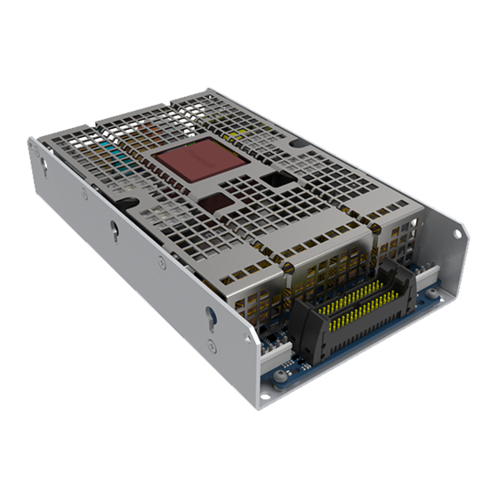
- Page 1 LiteMod 4HV USER GUIDE ©2021 Powersoft Keep this manual DO000XXX.00 for future reference...
- Page 2 Data are subject to change without notice. For latest update please refer to the online version available on www.powersoft-audio.com.
-
Page 3: Table Of Contents
14. Cable Kit - KT000349 6. Electrostatic Discharge (ESD) viii 14 : 1.Mains Cable – CB000727 7. LiteMod 4HV 14 : 2.Output cable, 4 x SE configuration – CB000731 14 : 3.Output cable, 2 x BTL configuration – CB000730 7 : 1.Welcome 14 : 4.Output cable, 2 x PTL configuration –... - Page 4 Page intentionally left blank ii | LiteMod 4HV | User guide...
-
Page 5: Important Safety Instructions
8. Do not defeat the safety purpose of the polarized or grounding- DO NOT USE THE UNIT AT ALTITUDES ABOVE 2000 M. type plug. 9. Only use attachments/accessories specified by Powersoft. DO NOT USE THE UNIT IN TROPICAL ENVIRONMENT. 10. Refer all servicing to qualified service personnel. Servicing is... -
Page 6: Importantes Instructions De Sécurité
CONTACTER LE CENTRE DE SERVICE AUTORISE POUR UN ENTRETIEN ORDINAIRE ET EXTRAORDINAIRE. IL EST ABSOLUMENT NÉCESSAIRE DE VÉRIFIER CES CONDITIONS FONDAMENTALES DE SÉCURITÉ ET, EN CAS DE DOUTE, D'OBTENIR UNE VÉRIFICATION PRÉCISE PAR DU PERSONNEL QUALIFIÉ. iv | LiteMod 4HV | User guide... -
Page 7: Instrucciones De Seguridad Importantes
EQUIPOS ELÉCTRICOS Y ELECTRÓNICOS (WEEE por sus siglas 6. No bloquee las aberturas de ventilación. Realice la instalación de en Inglés). acuerdo con las indicaciones de Powersoft. ENTRE 0°C Y +35°C 7. No instale cerca ninguna fuente de calor como, por ejemplo, DEGRADACIÓN POR ENCIMA DE 35°C. -
Page 8: Importanti Istruzioni Di Sicurezza
CONTATTARE IL CENTRO DI ASSISTENZA AUTORIZZATO PER ESEGUIRE LA MANUTENZIONE ORDINARIA E STRAORDINARIA. E’ ASSOLUTAMENTE NECESSARIO CONTROLLARE QUESTI REQUISITI FONDAMENTALI SULLA SICUREZZA E, IN CASO DI DUBBI, RICHIEDERE UN CONTROLLO ACCURATO DA PERSONALE QUALIFICATO. vi | LiteMod 4HV | User guide... -
Page 9: Regulatory Information
The Waste Electrical and Electronic Equipment Directive (WEEE Directive) aims to minimise the impact of electrical and electronic goods on the en- vironment. Powersoft S.p.A. comply with the Directive 2002/96/EC and 2003/108/EC of the European Parliament on waste electrical finance the cost of treatment and recovery of electronic equipment (WEEE) in order to reduce the amount of WEEE that is being disposed of in land-fill site. -
Page 10: Electrostatic Discharge (Esd)
Electrostatic Discharge Sensitive devices (ESDS) and assemblies are handled outside of full static protection packaging (i.e. within static control areas) should be pro- vided with some form of ground conductive or dissipative flooring. viii | LiteMod 4HV | User guide... -
Page 11: Litemod 4Hv | 1
LiteMod 4HV can be easily integrated into any ap- posal and can normally be recycled. pliance such as active loudspeakers and stand alone rack Rather than just throwing these materials away, please amplifiers. -
Page 12: Thermal Constraints
Module in a separate Be aware of as the highest ambient temperature air leakage vented chamber. as the highest operating temperature 2 | LiteMod 4HV | User guide... -
Page 13: Electromagnetic Compatibility (Emc) & Safety
M4 nut and bolt with proper split washer – grover Reject RF noise from input and output cabling by in- washer – to secure the earth terminal lug. stalling ferrite shields. Powersoft suggests the FAIR RITE 0431164181, or equivalent. Electromagnetic Compatibility (EMC) & Safety | 3... -
Page 14: Mechanical Drawings
Mechanical drawings 108,4 FIGURE 6: LiteMod4HV side and back plate (all dimensions in millimeters). 4 | LiteMod 4HV | User guide... -
Page 15: Connections
Terminals: SVH-41T_P1-1 Fan connector: Molex 22-01-2035 Terminals: KK 254 4809 series POWERSOFT S.p.A. Connections | 5 Via E.Conti, 5 - 50018 Scandicci (FI) - Italy Tel. +39 055 7350230 - fax +39 055 7356235 http://www.powersoft.it... -
Page 16: 2.1. Pl1 Pinout
Disable output stage PWM generator up to +5VDC Regulated -12VDC (+/-10%) supply output -12VDC OUT POWER (for audio circuits) Same as pin 14. Same as Max current available= 0,3A pin 14 and 21 on PL3000 6 | LiteMod 4HV | User guide... - Page 17 Scale Pin# Name Type Description Range Impedance Factor Regulated +12VDC (+/-10%) supply output +12VDC OUT POWER (for audio circuits) Same as pin 13. Same as Max current available= 1A pin 13 and 22 on PL3000 Output stages 1&2 temperature monitor. TEMPMON Highest temperature between channel 1 0-5VDC...
- Page 18 Channel 4 output stage protection monitor. 11VDC< VOH <13VDC / Open Collector - PROTECT 4 Low when output is in protect state 0VDC< VOL <1VDC 100KΩ Pullup VOUT4MON Channel 4 output voltage monitor 0-4,5VDC 20V/V 4,5KΩ POWER 8 | LiteMod 4HV | User guide...
-
Page 19: 2.4. Pl1001, Pl3001 Pinout
Scale Pin# Name Type Description Range Impedance Factor Differential= 3KΩ Channel 4 balanced input (inverting) / Common mode= 3.5KΩ (bal) IN 4- Channel 4 unbalanced input (inverting, 3,5KΩ (unbal) when shorting pin 29 to GND) 3VRMS input for full output Absolute MAX input= 8VRMS Differential= 3KΩ... -
Page 20: 4.Internal Signal Path Polarity
11 : 5.Output Configuration In order to increase the power’s supply energy stor- age efficiency, signals coming from channel pairs 1-2 are LiteMod 4HV can be configured in 5 different output reversed in polarity. type of connections: This ensures a symmetrical use of the voltage rails: if, 4 x SE (Single Ended): 4 indipendent channels. - Page 21 Parallel Parallel Parallel Parallel @ 8 Ω BTL @ 8 Ω BTL Parallel Parallel Parallel Parallel Parallel Parallel Parallel @ 4 Ω Parallel @ 4 Ω @ 8 Ω BTL @ 8 Ω BTL FIGURE 8: Short-circuited pins on the output connector. Parallel Parallel Parallel...
-
Page 22: Fan Installation
1) connettere ventola all'elettronica 2) far passare i componenti in gomma attraverso i fori della ventola lettronica ti in gomma ventola 12 | LiteMod 4HV | User guide REV. DATE DESCRIPTION MATERIAL... - Page 23 Errore: Nessun riferimento Errore: Nessun rife Errore: Nessun riferimento DATE 1: 2 Errore: Nessun riferimento POWERSOFT S.p.A. DRAWING Via E.Conti, 5 - 50018 Scandicci (FI) - Italy Tel. +39 055 7350230 - fax +39 055 7356235 CODE http://www.powersoft.it Fan installation | 13...
-
Page 24: Protections
13 : 2.2. Primary AC mains overvoltage protection several protection mechanisms triggered by harmful signal and temperature. Protection systems and triggers LiteMod 4HV has a 400 VAC temporary tolerant power are independently implemented in the power supply supply. AC mains overvoltage threshold is set to about 280 section (power supply protection) and the amplifier section . -
Page 25: 3.Amplifier Protections
13 : 2.4. Total power limiter described in the table below, and will then cycle the entire process indefinitely. When the module detects a long term output current of >11 A, and an output power grater than 700 W, it will limit the Time Cycle # output power accordingly. -
Page 26: Cable Kit - Kt000349
Cable Kit - KT000349 For module evaluation only. 14 : 1.Mains Cable – CB000727 Bill of Materials Part Description MPN / Specs PowerCon NAC3MPA-1 JST connector VHR-3N JST Contacts SVH-21T-P1.1 (22 ~ 18 AWG), SVH-41T-P1-1 (20 ~ 16 AWG) Fuse Holder SCI R3-32B2 Fuse LITTELFUSE 326 15AT... -
Page 27: 2.Output Cable, 4 X Se Configuration - Cb000731
14 : 2.Output cable, 4 x SE configuration – CB000731 Bill of Materials Part Description MPN / Specs Speakon NL4MP-UC JST Connector VHR-6N JST Contacts SVH-21T-P1.1 (22 ~ 18 AWG), SVH-41T-P1-1 (20 ~ 16 AWG) White Cable 16 AWG Blue Cable 16 AWG Orange Cable 16 AWG... -
Page 28: 3.Output Cable, 2 X Btl Configuration - Cb000730
N.C. N.C. N.C. N.C. N.C. BLUE GREY N.C. N.C. N.C. N.C. N.C. N.C. N.C. N.C. N.C. N.C. N.C. N.C. CH 1 - 3 PIN 1 OUT 1+2 OUT 3+4 CH 2 - 4 18 | LiteMod 4HV | User guide... -
Page 29: 4.Output Cable, 2 X Ptl Configuration - Cb000733
14 : 4.Output cable, 2 x PTL configuration – CB000733 Bill of Materials Part Description MPN / Specs Speakon NL4MP-UC JST Connector VHR-6N JST Contacts SVH-21T-P1.1 (22 ~ 18 AWG), SVH-41T-P1-1 (20 ~ 16 AWG) White Cable 16 AWG Blue Cable 16 AWG Orange Cable 16 AWG... -
Page 30: 5.Output Cable, 1 X Pbtl Configuration - Cb000732
WHITE N.C. N.C. N.C. N.C. N.C. N.C. BLUE BLUE LOOP N.C. N.C. LOOP N.C. N.C. LOOP N.C. N.C. LOOP N.C. N.C. CH 1 - 3 PIN 1 OUT 1 CH 2 - 4 20 | LiteMod 4HV | User guide... -
Page 31: Evaluation Board - Kt000291
15 : 1.Switch functions The KT000291 is a basic evaluation board adapting up to 4 XLR inputs into two Powersoft IDC 34 poles connectors. It includes two switches able to parallel inputs into two paralleled couples. Additional test points help the user to monitor some readout signals and provide some signals to the amplifier. - Page 32 Positive Auxiliary Power Supply -12VDC 1/2 14,21 Negative Auxiliary Power Supply +VCCMON 1/2 16,19 Positive Rail voltage monitor (20V/V) -VCCMON 1/2 17,18 Negative Rail voltage monitor (20V/V) PL2 Signals on PL1/2 connector (channels 1 and 2) 22 | LiteMod 4HV | User guide...
- Page 33 Test Point Name type PL3/4 IDC 34 poles pin # Description 5,8,27,30 Secondary ground MUTE 3/4 15,20 Mute channels 3 and 4 (active low) RX232 3/4 reserved TX232 3/4 reserved +5VDC 3/4 +5V (Max absorption 0,1A) 5,8,27,30 Secondary ground IN+3 Positive input channel 3 IN-3 Negative input channel 3...
-
Page 34: Support And Warranty
Support and warranty This Powersoft product contains no user-serviceable parts. All warranty repairs must be carried by a certified technician operating in a Powersoft Authorized service center. To learn more about warranty terms and conditions, visit powersoft.com/warranty. For any service related enquire, please write to service@powersoft.com. -
Page 35: Specifications
Specifications AC Mains Power Output Power, all channels driven symmetrically Universal input, regulated Switch Mode with Power supply # of channels 4 ch 2 ch 2 ch 1 ch Nominal voltage 100-240 V AC @ 50/60Hz Configuration PBTL Operating Voltage 85-264 V AC 2 Ω... - Page 36 Powersoft S.p.A. Via Enrico Conti, 5 50018 Scandicci (FI) Italy Tel: +39 055 735 0230 Fax: +39 055 735 6235 For questions about sales, application and technical support, service, maintanance, and compliance, please refer to the powersoft website powersoft-audio.com...
Need help?
Do you have a question about the LiteMod 4HV and is the answer not in the manual?
Questions and answers