Table of Contents
Advertisement
Quick Links
This manual contains important safety and operation instructions for correct use of the battery charger.
Read through the manual and pay special attention to the markings and labels of the charger,
Pay special attention to these two types of notices used in this manual.
Failure to heed this warning may cause injury to persons and damage to Equipment.
Failure to observe this warning may result in damage to equipment
WARNING:
●
The charger is not designed for any life saving application.
●
The charger is designed for in-door use. Protect the charger from ingress of water.
●
This charger is made to charge only properly sized lead acid batteries and Lithium Fe PO4 (LFP).
●
Don't recharging non-rechargeable batteries.
●
Charging other types of battery or under-sized lead acid batteries may cause fire
or explosion.
●
Install the charger in accordance with all local codes.
●
Do not use the charger if it has been dropped or damaged.
●
Never attempt to charge a frozen LEAD BASED battery or Lithium FePo4 battery below 0 C.
●
Never attempt to charge a damaged battery.
●
Wear protective goggles and turn your face away when connecting or disconnecting the battery.
●
Never place the charger on top of a battery.
●
Never smoke, use an open flame, or create sparks near battery or charger during normal charging
operation as batteries may give out explosive gas.
●
Do not charge batteries in an enclosure (box- in) due to possible explosion of entrapped explosive gas.
●
If the charger does not work properly or if it has been damaged, unplug all DC connections.
Copy Right
All rights reserved.
No part of this publication may be reproduced, or transmitted in any form or by any means without the written
permission from Manson Engineering Industrial Ltd.
Changes in the manual.
Manson Engineering Industrial Ltd. has the right to update and change the content of this manual without
any prior notice and obligation.
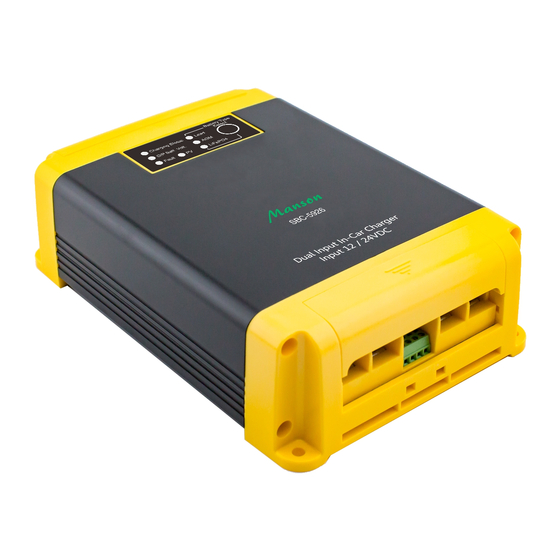
24V In-Car Charger
Dual Input (Solar MPPT & DC)
Operation manual
Keep this manual in a safe place for quick reference at all times.
battery and equipment connected to the battery system.
and improper functioning of the Charger.
SBC-5936
Advertisement
Table of Contents

Related Manuals for Manson Engineering Industrial SBC-5936


Summary of Contents for Manson Engineering Industrial SBC-5936
- Page 1 No part of this publication may be reproduced, or transmitted in any form or by any means without the written permission from Manson Engineering Industrial Ltd. Changes in the manual. Manson Engineering Industrial Ltd. has the right to update and change the content of this manual without any prior notice and obligation.
- Page 2 Disclaimer Exclusions for documentation, Indemnity and Product application. Manson Engineering Industrial Ltd. (Manson) Assumes no warranty to the accuracy, suitability of technical information given in the user manuals or other documentation. Undertakes no responsibility or liability of losses, damages and related expenses whether specific, direct, indirect consequential or accidental which might result from the use of information given in this manual.
-
Page 3: Table Of Contents
Table of content Introduction Features Protections Supplied Accessories Installation Procedure Indicators and controls Battery Type selection Solar panel and DC source dual inputs Charger control modes Connect & Wiring Diagram P.10 Specification P.11 Troubleshooting P.12 Figure index Fig. 1 correct installation direction Fig. -
Page 4: Introduction
Introduction Especially designed for vehicles with Smart Alternator, Start-Stop, Regenerative Braking system This charger is designed to deal with the issue of wide swing of output voltages from the smart alternator, braking regenerative EURO 5/6 vehicles in fully charging the house battery. It is suitable for use with all old alternator system and distant house battery. -
Page 5: Supplied Accessories
Supplied Accessories ● Remote LED Indicator Module (with 2M cable) like the unit front panel. ● 4 heavy duty electrical eye connectors. ● One plastic wire guide. ● Double side sticker tape for the Remote Indicator Module. ● Two thin wires for Pin Connections ●... -
Page 6: Indicators And Controls
Fig. 1: correct installation direction Indicators and Controls Fig. 2: 7 LEDs indicators and one SET button SET button The SET button is for selection of battery & deactivate Ignition Control Mode. 5 second long press for battery selection. 15 second long press to deactivate Ignition Control Mode. Charging Status LED for LEAD ACID Battery –... -
Page 7: Battery Type Selection
PV LED The PV LED is ON when voltage from PV panel is >14.4V. PV LED flickers with the changes of PV voltages. PV LED is off at night time .This is a good way to check for open- circuit in the solar connection in day time. -
Page 8: Charger Control Modes
Charger Control Modes There are 3 automatic charge modes plus one manual ON-OFF to switch on and off the charger to give the optimal charging current to the auxiliary battery. Automatic Ignition Control Mode It synchronizes ON/OFF of the DC-DC charger with the car’s ignition. This mode requires connection to the car’s Ignition Signal Terminal 15 see wiring diagram (page 10) electrical circuit which gives out a positive DC Voltage from the car’s electrical wiring when the ignition is turned on. - Page 9 Cancel Ignition Control Take out connection to the Ignition pin 7.(page 8 ) Press and hold button for around 15 seconds until the 3 LED battery type flash at the same time. Iii) Release button and charger changes to Input Voltage Control. Input Voltage Control Mode This mode requires increased voltage (>13.4V) of the starter battery which is only possible with short thick cable connection and old type alternator with sufficiently high and stable charging voltage.
-
Page 10: Connect & Wiring Diagram
Connect & Wiring Diagram Individual fuse/ breaker is required to be close to starting battery (charger input) and close to house battery (charger output wire). Fuse at the solar panel to the rating of the short circuit current of the solar panel. Fig. -
Page 11: Specification
Specification Rated output power 12A at 27.6VDC Efficiency ≥90% Input Voltage DC Input Voltage Range 9 - 16VDC (12VDC Input) / 18 - 32VDC (24VDC Input) Max. Solar Panel Open Circuit Voltage 30VDC No load input current <25mA Output (Charge) Voltage Battery Type Absorption Float... -
Page 12: Troubleshooting
Trouble Shooting The Fault LED is solid on when a protection is triggered and output of the charger is off. When the cause of the fault has been clear up, Fault LED becomes off and charger returns to normal operation. Almost all the protections are by software design and self recoverable, once the cause of fault has been dealt with.
Need help?
Do you have a question about the SBC-5936 and is the answer not in the manual?
Questions and answers