
Related Manuals for Wheatstone Corporation E-4


Summary of Contents for Wheatstone Corporation E-4
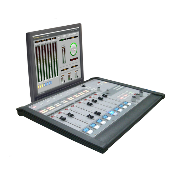
- Page 1 E-4 Digital Control Surface TECHNICAL MANUAL 600 Industrial Drive, New Bern, North Carolina, USA 28562...
- Page 2 E-4 Digital Control Surface Technical Manual E-4 Digital Control Surface Technical Manual E-4 Digital Control Surface Technical Manual E-4 Digital Control Surface Technical Manual E-4 Digital Control Surface Technical Manual ©2009 Wheatstone Corporation WHEATSTONE CORPORATION 600 Industrial Drive New Bern, North Carolina 28562...
- Page 3 Wheatstone could void the user's authority to operate this equipment. R R R R R M M M M M ! ! ! ! ! E-4 / Jan 2009 E A D E A D E A D E A D...
- Page 4 Wheatstone will not be liable for damage resulting from improper cleaning and maintenance. R R R R R M M M M M ! ! ! ! ! E-4 / Jan 2009 E A D E A D E E E E E E A D...
-
Page 5: Table Of Contents
TB BUS- Switch ....................2-5 Bus-Minus Outputs ....................2-5 Fader ........................2-6 Channel ON Switch ..................... 2-6 Channel OFF Switch ................... 2-6 Channel Status Buttons Display ................2-6 page Contents – 1 E-4 / Jan 2009 E-4 / Nov 2009... - Page 6 Machine Logic ......................3-22 Optional Glass E Interface ..................3-23 Network Settings ...................... 3-25 E-4 GUI Main Tab Screen Controls ................. 3-27 E-4 GUI Input Tab Screen Controls ................ 3-28 E-4 GUI MixMinus Tab Screen Controls ..............3-29 E-4 GUI Presets Tab Screen Controls ..............3-30 E-4 GUI Events Tab Screen Controls ..............
- Page 7 MNE-4 Master Panel Switch Card Schematic ......................... 5-7 Load Sheet ....................... 5-11 HC-3 Host Controller Card Schematic ........................ 5-12 Load Sheet ....................... 5-16 PSU-1 Power Supply Schematic ........................ 5-17 Load Sheet ....................... 5-18 page Contents – 3 E-4 / Jan 2009...
- Page 8 Modifying The Options Text File ................A-6 A Simple Example From The File ................A-7 A Second Example ....................A-8 An Example File - Complete ..................A-9 Appendix 3 Replacement Parts List .............. A-15 page Contents – 4 E-4 / Jan 2009...
- Page 9 Failsafe Dual Redundant Supply ................1-5 Energizing ....................... 1-5 I/O Connections ................1-6 Getting Started ................1-8 Log-In ..................1-8 Tabbed Navigation ..............1-9 Surface Software Version ............1-10 page 1 – 1 E-4 / Jan 2009 E-4 / Nov 2009...
-
Page 10: Introduction
A simpler version of our E-6 surface, the E-4 control surface carries less features, keeping the control surface simple to use yet giving the operators the features needed for some of the most demanding shows. -
Page 11: Control Surface Placement
Cutout dimensions (in inches) are shown in the drawings below for 5 available frame sizes. Do not connect the E-4 control surface to its power supply (and do not connect the power supply to the AC power line) until instructed to do so. -
Page 12: Power Supply
Rear view of the PSU-1 rackmount power supply If failsafe redundant sup- The E-4 control surface is powered by a Wheatstone Model PSU-1 plies have been ordered, rackmount power supply. This unit occupies two 19” wide rack spaces you will be installing two PSU-1 units. -
Page 13: Failsafe Dual Redundant Supply
BOTH rackmount supplies powered up and connected to their associ- ated equipment. Energizing Assuming the E-4 control surface mainframe is properly placed, and its PSU-1 power supply (or supplies) correctly rackmounted and connected to the control surface, you may now energize the rackmount power supply by plugging it into the AC mains. -
Page 14: I/O Connections
G E N E R A L I N F O R M A T I O N I/O Connections All user wiring to and from the E-4 control surface is made via connectors located on the control surface’s rear panel. Two 5-pin male connectors at the center of the control surface’s rear are for power supply connections. - Page 15 G E N E R A L I N F O R M A T I O N page 1 – 7 E-4 / Jan 2009 E-4 / Nov 2009...
-
Page 16: Getting Started
G E N E R A L I N F O R M A T I O N Getting Started The E-4 control surface comes with the E-4 Embedded Graphical User Interface (GUI) program, intended to be straightforward in use, controlling and displaying graphics, produc- tion tools, and set up screens. -
Page 17: Tabbed Navigation
Settings are stored as Presets. The Preset Pane allows you to manage and apply presets to Sources and faders. Events Tab - the E-4 can store a “snapshot” of the entire control surface in a file called an EVENT. The Event Pane is divided into two sections. The Event Recall section lets you recall previously saved Events. -
Page 18: Surface Software Version
G E N E R A L I N F O R M A T I O N Surface Software Version In the event that you need to consult the factory about the E-4 control surface, you may need to have the surface software version number available. Click the Wheatstone logo on the top of the start-up screen to display the “INFORMA-... - Page 19 CUE Switch ......................2-5 TB BUS- Switch ....................2-5 Bus-Minus Outputs .................... 2-5 Fader ........................2-6 Channel ON Switch ................... 2-6 Channel OFF Switch ..................2-6 Channel Status Buttons Display ................ 2-6 page 2 – 1 E-4 / Jan 2009...
-
Page 20: Chapter 2 - Input Panel (Ipe-4)
Input Tab located on the VGA monitor. The Input Tab is the center of control for the E-4 surface. Here you find easy access to most of the fader strip’s parameters. The hardware LED indi- cators on the fader strip let the operator know when a particular function is active. -
Page 21: Input Tab Display
This feature is espe- cially useful in large systems with lots of sources. Visibility for input sources can also be set from the surface. This procedure is outlined in Chapter 3. page 2 – 3 E-4 / Jan 2009... -
Page 22: Fader Mode Controls And Indicators
The user can save all adjustments with the SAVE button. Pressing the SAVE button will bring up the “SAVE TO” form that allows all changes to be saved to a channel, a source, an event, or a preset. page 2 – 4 E-4 / Jan 2009... -
Page 23: Other Physical Switches And Leds
Bus-Minus mix outputs for each surface fader appear as Sources in the Surface signal area of XPoint, typically located above source signal ID1001. A typical Bus-Minus output signal name is E1BM01 but the exact name depends on the fader and surface ID number. page 2 – 5 E-4 / Jan 2009... -
Page 24: Fader
Operators should be made aware that logic associated with a signal will not act as expected when the logic lock indicator is ON. page 2 – 6 E-4 / Jan 2009... - Page 25 Control Room Section ..................3-9 Headphone Section ................... 3-9 Studio Section ....................3-10 Talkback to Studio ................... 3-10 E-4 Monitor Options ..................3-10 Events ........................3-11 Enter Button ......................3-12 Help Button ......................3-12 Control Modes - User Permissions ............... 3-13 Presets Tab Functions ..................
- Page 26 M A S T E R P A N E L E-4 GUI Main Tab Screen Controls ..............3-27 E-4 GUI Input Tab Screen Controls ..............3-28 E-4 GUI MixMinus Tab Screen Controls .............. 3-29 E-4 GUI Presets Tab Screen Controls ..............3-30 E-4 GUI Events Tab Screen Controls ..............
-
Page 27: Chapter 3 - Master Panel (Mne-4)
M A S T E R P A N E L Master Panel (MNE-4) Controls and Functions The E-4 digital audio control surface is equipped with one MASTER panel. This panel contains numerous controls, including INPUT SOURCE select, PAN, and CUE... - Page 28 ID1001. All surface inputs (faders, talk back, monitor source selects, etc.) appear as destinations, also beginning at signal ID1001. Surface signals may be routed just like any user i/o. E-4 Mixer Outputs page 3 – 4 E-4 / Jan 2009...
- Page 29 SAVE TO. Creating new presets is covered later in the manual (see page 3-15). page 3 – 5 E-4 / Jan 2009...
-
Page 30: Mxm Assign Switches
LED mode, radio stations tend to operate in the NO mode and TV stations in the YES mode. Set this as required for your facility. Give Inverted Mode a try; it may actually be easier to use. page 3 – 6 E-4 / Jan 2009... -
Page 31: Mxm Talkback
TB input using either XPoint software or the E-4’s built in Route function. The TB signal may be any Source signal in the router, including any MXM bus. The E-4’s TB input signal is a factory defined surface Destination signal with a name similar to E1TBack. The actual name depends on how many surfaces you have. -
Page 32: Monitor Speaker Controls
NOTE: If a monitor output is muted and you turn the level control all the way up, then remove the condition that has the monitor muted, the sound in the monitor speakers (or headphones) will suddenly be VERY LOUD! page 3 – 8 E-4 / Jan 2009... -
Page 33: Source Select Switches
MUTE appears in the center of the monitor’s meter display. The CR level may also be locked to a user defined volume level. See the E-4 Monitor Options section below. Headphone Section The built in HP amp output signal appears at the headphone jack, mounted on the right-hand front of the control surface’s lower mainframe pan. -
Page 34: Studio Section
Destination signal with a name similar to E1TBk. The actual name depends on how many surfaces you have. There is only one TB bus input on the E-4. You can use Programmable Buttons to momentarily route other sources to the Studio output. -
Page 35: Events
M A S T E R P A N E L Events The E-4 includes a snapshot save and recall feature that saves all of the surface’s switch, level, and DSP settings to a unique Event file. These saved Events may be recalled as required at any time. -
Page 36: Enter Button
Help Button Pressing the HELP button opens a HELP menu on screen for when Talent needs help with settings such as a mix- minus, or with surface operation in general. page 3 – 12 E-4 / Jan 2009... -
Page 37: Control Modes - User Permissions
M A S T E R P A N E L Control Modes - User Permissions The E-4 control surface is operated in one of four modes: Intern, Operator, Production, and Engineering. Engineering mode, by default, allows the user to perform all surface functions. - Page 38 (current) passcode and then enter the new passcode twice and click OK to effect the change. Once a given control mode is selected for a surface, that setting will persist through a power cycle or surface reset. page 3 – 14 E-4 / Jan 2009...
-
Page 39: Presets Tab Functions
Press the Input tab and click the LOAD button on the bottom of the Input screen to display the PRESET LOAD screen. Choose the PRESET TYPE, highlight the desired preset, and press LOAD. page 3 – 15 E-4 / Jan 2009... -
Page 40: Save
A METERS set- ting on the Options Tab allows you to turn off Auto-Cue to this meter. page 3 – 16 E-4 / Jan 2009... -
Page 41: Timer Section
(via the GUI) input modules can automatically reset the timer display (located on the upper-left side of the main E-4 GUI screen) to zero and start a new count, allowing the announcer to easily track his own pace. The AUTO button on the Monitor Panel must be lit to enable this function. -
Page 42: Programmable Buttons
XPoint application. See the E-Se- ries Network System manual for details. Some of the spare button programming can be done via the E-4 GUI. Press the Options tab and choose Programmable But- tons from the AVAILABLE OPTIONS scroll down list to display the Program- mable Buttons form. - Page 43 XPoint - the button LED is controlled by a system DIO which is also configured in XPoint • Software Controlled - in this mode the button’s function is set up by the E-4 GUI using the EDIT button, as described below - the LED is controlled by the surface and is on while the button is pressed and off when released •...
-
Page 44: Vdip Settings
You may configure VDip from the E-4 directly or by using the VDip dialog box in XPoint software. It is conve- nient to configure VDip right on the E-4, but you may have to use XPoint if you have other surface models. - Page 45 ON. There are five STUDIO MUTES checkboxes, one for each monitor section plus one for CUE. The checked boxes show which speakers are muted. Note that the Studio 2 mute has no effect on the E-4 surface. STUDIO TALLIES—Turning the channel ON can activate a remote tally indicator.
-
Page 46: Machine Logic
M A S T E R P A N E L Machine Logic The surface’s start/stop logic options can be selected via the E-4 GUI. Press the Options tab and choose Misc Options from the AVAILABLE OPTIONS scroll down list to display MA- CHINE LOGIC choices. -
Page 47: Optional Glass E Interface
Glass E interface to func- tion. In the E-4 GUI press the Op- tions Tab and choose Misc Options from the AVAILABLE OPTIONS... - Page 48 M A S T E R P A N E L Enter the surface’s IP address and the Port, User name, and Password you previously set up at the E-4, and you should then see screens similar to following two screens (shown for E-6...
-
Page 49: Network Settings
You can manually enter this infor- mation by turning off Automatic mode and using the numbered keypad on the screen. Pressing NEXT will advance to the next field. page 3 – 25 E-4 / Jan 2009 E-4 / Apr 2009... - Page 50 Options Tab and select Network Settings from the drop down menu. If all information was entered prop- erly the WheatNet-IP STATUS will display CONNECTED. The E-Series surface has been successfully configured. page 3 – 26 E-4 / Jan 2009 E-4 / Apr 2009...
-
Page 51: Gui Main Tab Screen Controls
Functions display: Clock, timer, current event, and switched meter Program meters Click on EXT windows to choose source Channel Select / Status Monitor Controls Buttons Access Authorization E-4 GUI Main Tab Screen Controls page 3 - 27 E-4 / Jan 2009... -
Page 52: Gui Input Tab Screen Controls
ON/OFF. to lock monitor levels feeding amplifiers. Separate password protected login for engineers, jocks, interns. MUTE labels let you see when speakers are muted. E-4 GUI Input Tab Screen Controls page 3 - 28 E-4 / Jan 2009... -
Page 53: Gui Mixminus Tab Screen Controls
MXM LED is lit, the audio on that fader is NOT going to the bus. It is very easy to see which faders are “minused” out. E-4 GUI MixMinus Tab Screen Controls page 3 - 29 E-4 / Jan 2009... -
Page 54: Gui Presets Tab Screen Controls
Button Bar to save a new preset Shows which fader strips have the selected preset applied to them Shows which sources have the selected preset applied to them E-4 GUI Presets Tab Screen Controls page 3 - 30 E-4 / Jan 2009... -
Page 55: Gui Events Tab Screen Controls
RENAME—3 guesses? Just click on the event name and the virtual keyboard opens up. DELETE—Just click on the event name, click DELETE and confirm. E-4 GUI Events Tab Screen Controls page 3 - 31 E-4 / Jan 2009... -
Page 56: Gui Options Tab Screen Controls
Options Manager tab — Provides access to a whole host of system options. Some are self explanatory, but see the Options Details section for details. E-4 GUI Options Tab Screen Controls page 3 - 32 E-4 / Jan 2009... -
Page 57: Gui Input Tab Screens
Press SET on a fader to open main Choose fader sources INPUT screen Use the Button Bar to navigate various input screens Preset Load Save VDIP E-4 GUI Input Tab Screens page 3 - 33 E-4 / Jan 2009... -
Page 58: Gui Options Tab Screens
User Configuration Programmable Buttons Crosspoint Visibility Miscellaneous Options Network Settings VDIP Settings Source Visibility Monitor Configuration This screen available only for the system with WheatNet-IP engine BLADE. E-4 GUI Options Tab Screens page 3 - 34 E-4 / Apr 2009... - Page 59 “ETH” RJ-45 - Main Ethernet Connector ..............4-4 “CAT5” RJ-45 - Mixer Link Connector ..............4-4 “HEADPHONE” - Headphone Connector ............... 4-4 Typical Ethernet Cable .............. 4-5 Typical Crossover Cable ............4-5 HC-3 Pinouts Drawing ............... 4-6 page 4 – 1 E-4 / Jan 2009...
-
Page 60: Overview
A video port is provided for the user-provided VGA monitor, and a keyboard port is for factory use only. The purpose of the host controller is to provide control of the E-4 control surface. The HC-3 communicates to the XPoint Configuration PC via TCP/IP over Ethernet through a standard ethernet hub or switch. -
Page 61: Mixer Link Wiring
These dipswitch positions are reserved for future use. SW1 Position 4 - CAT5 Enable Position 4 of SW1 must be in the on position in order to activate the CAT5 mixer link connections. page 4 – 3 E-4 / Jan 2009... - Page 62 Pin 7 – HDPN RT HI Pin 8 – HDPN RT SH Pin 3 – HDPN RT LO Pin 1 – N/C Pin 2 – N/C Pin 6 – N/C page 4 – 4 E-4 / Jul 2009 E-4 / Jan 2009...
- Page 63 RXD - Orange Green RXD + TXD + White/Green White/Orange RJ-45 RJ-45 Plug Blue Blue Plug White/Blue White/Blue RXD - TXD - Green Orange White/Brown White/Brown Brown Brown SED FOR MIXER LINK CONNECTOR page 4 – 5 E-4 / Jan 2009...
- Page 64 RXD - RXD - LN LED LK LED "HEADPHONE" Female DB-9 These are line level inputs 5 4 3 2 1 to the internal amplifiers that feed the surface’s head- phone jack. page 4 – 6 E-4 / Jan 2009...
- Page 65 MNE-4 Master Panel Switch Card Schematic ......................... 5-7 Load Sheet ....................... 5-11 HC-3 Host Controller Card Schematic ........................ 5-12 Load Sheet ....................... 5-16 PSU-1 Power Supply Schematic ........................ 5-17 Load Sheet ....................... 5-18 page 5 – 1 E-4 / Jan 2009...
- Page 66 DATE DRAWN 1-30-07 600 Industrial Drive New Bern, NC 28562 CHECKED __________________________ SWITCH LED DRIVE LOW ISSUED SIZE FSCM NO. DWG. NO. 84S0170-1 W# 700886 IPE-6 PCB 1 OF 2 SCALE SHEET page 5 - 2 E-4 / Jan 2009...
- Page 67 DATE MDL_CLK DRAWN FDR_2.5REF 1-30-07 600 Industrial Drive New Bern, NC 28562 FADER 1 CHECKED DS46 ISSUED SIZE FSCM NO. DWG. NO. 84S0170-2 W# 700886 IPE-6 PCB 2 OF 2 SCALE SHEET page 5 - 3 E-4 / Jan 2009...
- Page 69 - SA UR US - Sergey Averin - APPROVALS DATE DRAWN 600 Industrial Drive 10-25-06 New Bern, NC 28562 CHECKED SIZE FSCM NO. DWG. NO. 84S0172 ISSUED W# 700888 SCALE ONSE-6A PCB SHEET 1 OF 1 page 5 - 5 E-4 / Jan 2009...
- Page 70 S C H E M A T I C D R A W I N G S ONSE-4 4 Inputs Panel On/Off Switch Load Sheet page 5 – 3 page 5 – 6 E-4 / Jan 2009...
- Page 71 DRAWN WWP/SA 3-26-07 600 Industrial Drive __________________________ New Bern, NC 28562 SWITCH LED DRIVE LOW CHECKED ISSUED SIZE FSCM NO. DWG. NO. 84S0171-1 W# 700887 SCALE MNE-6B PCB SHEET 1 OF 4 page 5 - 7 E-4 / Jan 2009...
- Page 72 FDR_2.5REF APPROVALS DATE DRAWN AD_ST2 SA/WWP 3-26-07 600 Industrial Drive New Bern, NC 28562 CHECKED 100K ISSUED SIZE FSCM NO. DWG. NO. 84S0171-2 W# 700887 MNE-6B PCB 2 OF 4 SCALE SHEET page 5 - 8 E-4 / Jan 2009...
- Page 73 - SA UR US - Sergey Averin - APPROVALS DATE DRAWN SA/WWP 3-26-07 600 Industrial Drive New Bern, NC 28562 CHECKED ISSUED SIZE FSCM NO. DWG. NO. 84S0171-3 W# 700887 MNE-6B PCB 3 OF 4 SCALE SHEET page 5 - 9 E-4 / Jan 2009...
- Page 74 - SA UR US - Sergey Averin - APPROVALS DATE DRAWN SA/WWP 3-26-07 600 Industrial Drive New Bern, NC 28562 CHECKED ISSUED SIZE FSCM NO. DWG. NO. 84S0171-4 W# 700887 MNE-6B PCB 4 OF 4 SCALE SHEET page 5 - 10 E-4 / Jan 2009...
- Page 75 MNE-4 Master Panel Switch Card - Load Sheet page 5 – 11 E-4 / Jan 2009...
- Page 76 C100 C104 C109 C110 C112 CHECKED CUE_I_LO GLOBAL_ARB CUE_I_HI 0.1uF 100uF 0.01uF 0.1uF 0.1uF 0.1uF 0.1uF ISSUED SIZE FSCM NO. DWG. NO. 84S01xx W# 700790 HC-3B PCB 1 OF 4 SCALE SHEET page 5 - 12 E-4 / Jan 2009...
- Page 77 - SA UR US - Sergey Averin - APPROVALS DATE DRAWN 10-19-06 600 Industrial Drive New Bern, NC 28562 CHECKED ISSUED SIZE FSCM NO. DWG. NO. 84S01xx W# 700790 HC-3B PCB 2 OF 4 SCALE SHEET page 5 - 13 E-4 / Jan 2009...
- Page 78 R4 47 AT_P4 0.01uF 0.01uF 0.01uF 0.01uF 0.01uF 0.01uF 0.01uF 0.01uF 0.01uF 0.01uF 0.01uF 0.01uF ISSUED SIZE FSCM NO. DWG. NO. 84S01xx 8952_RX+ AT_P3 W# 700790 HC-3B PCB 3 OF 4 SCALE SHEET page 5 - 14 E-4 / Jan 2009...
- Page 79 2.5V 0.1uF 100uF 47uF 0.01uF 0.01uF 0.01uF 0.01uF 0.01uF 0.01uF 0.01uF 0.01uF 0.01uF 0.01uF 0.01uF 0.01uF ISSUED SIZE FSCM NO. DWG. NO. 84S01xx W# 700790 HC-3B PCB 4 OF 4 SCALE SHEET page 5 - 15 E-4 / Jan 2009...
- Page 80 HC-3 Host Controller Card - Load Sheet page 5 – 16 E-4 / Jan 2009...
- Page 81 - SA UR US - Sergey Averin - APPROVALS DATE 600 Industrial Drive DRAWN 2-3-06 New Bern, NC 28562 CHECKED SIZE FSCM NO. DWG. NO. 00S0034 ISSUED W# 700828 PSU-1B PCB 1 OF 1 SCALE SHEET page 5 - 17 E-4 / Jan 2009...
- Page 82 S C H E M A T I C D R A W I N G S PSU-1 Power Supply Load Sheet page 5 – 4 page 5 – 18 E-4 / Jan 2009...
- Page 83 Modifying The Options Text File ................A-6 A Simple Example From The File ................A-7 A Second Example ....................A-8 An Example File - Complete ..................A-9 Appendix 3 Replacement Parts List .............. A-15 page A – 1 E-4 / Jan 2009...
- Page 84 A P P E N D I C E S Appendix 1 Contents Control Surface Clock ..............A-3 Setting the Time ......................A-3 Update Options ......................A-3 Synchronize ......................A-3 Battery Backup ......................A-4 page A – 2 E-4 / Jan 2009...
-
Page 85: Control Surface Clock
A P P E N D I C E S Control Surface Clock The main E-4 GUI screen includes the digi- tal and analog displays of a time of day clock. Setting the Time Setting the time of the control surface’s... -
Page 86: Battery Backup
(it will do this for 3 to 4 weeks). To activate battery backup of the control surface’s clock simply pull out the yellow strip from the HC-3 board, as shown on the picture below. page A – 4 E-4 / Jan 2009... - Page 87 Options Text File ................A-6 Introduction ....................... A-6 Modifying The Options Text File ................A-6 A Simple Example From The File ................A-7 A Second Example ....................A-8 An Example File - Complete ..................A-9 page A – 5 E-4 / Jan 2009...
-
Page 88: Options Text File
Options Text File Introduction There are a number of operational features on the E-4 surface that are controlled by the contents of the Options Text File (E4_OPTS.TXT) that resides on the surface's flash drive. In order to configure these features it is necessary to modify this file. -
Page 89: A Simple Example From The File
The edited line must follow the established syntax precisely or the surface may not behave as expected. page A – 7 E-4 / Jan 2009... -
Page 90: A Second Example
You may have fewer or greater modes available depending on the surface model and vintage. In any event you can select the same or a different mode from the available modes for each programmable button on the surface. page A – 8 E-4 / Jan 2009... -
Page 91: An Example File - Complete
MM2:0 MM3:0 MM4:0 // -------------------------------- // BUS MINUS OPTIONS // -------------------------------- // Syntax: DIRECT_OUT#:? // # is the input fader number (1 - 40) // ? is the mode (default = 0)... page A – 9 E-4 / Jan 2009... - Page 92 3 = Momentary, Button is active when held down, LED controlled by DIO 4 = Automation, Button & LED are controlled by automation interface 5 = Preset Select, Button selects pre-configured preset, LED controlled by Surface SPARE1:2 SPARE2:2 SPARE3:2 page A – 10 E-4 / Jan 2009...
- Page 93 INVERT_MM:0 // Syntax: CUE_DEFEAT_STU1:? // Syntax: CUE_DEFEAT_STU2:? // Syntax: CUE_DEFEAT_HDPN:? // Syntax: CUE_DEFEAT_CR:? // ? 1 = cue defeat to this monitor, 0 cue enabled to this monitor. CUE_DEFEAT_STU1:1 CUE_DEFEAT_STU2:1 CUE_DEFEAT_HDPN:1 CUE_DEFEAT_CR:1 page A – 11 E-4 / Jan 2009...
- Page 94 2 = supress machine start/stop DIOs when input channels on/off via remote on/off DIO. 3 = supress machine start/stop DIOs when input channels on/off via ACI and/or DIO. ACI_DISABLE_MSS:0 // Syntax: PCI_NORMAL:0xRRGGBB // 0x848484 (default) = Color for dialog backgrounds. PCI_NORMAL:0x848484 page A – 12 E-4 / Jan 2009...
- Page 95 // Syntax: INACTIVE_TAB_TEXT:0xRRGGBB // 0x333333 (default) = Color for text on inactive tabs INACTIVE_TAB_TEXT:0x333333 DEBUG_FLAGS:0x00000000 CLOCK_MODE:12 CLOCK_SECONDS_COUNTDOWN:20 CR_LEVEL_LOCK:-1 HDPN_LEVEL_LOCK:-1 STU1_LEVEL_LOCK:-1 STU2_LEVEL_LOCK:-1 PGMA_LABEL:PGM A PGMB_LABEL:PGM B PGMC_LABEL:PGM C PGMD_LABEL:PGM D EVENTS_SAVE_ON_OFF:0 STARTUP_CHANNELS_OFF:0 VISIBILITIES_SHOWS_LOCATIONS:1 page A – 13 E-4 / Jan 2009...
-
Page 96: Appendix 3
Replacement Parts List .............. A-15 For the most part there are no user-replaceable parts in the E-4 control surface. Exceptions are those controls and components that in the course of normal use may need maintenance (i.e., faders, pots, ON switches, etc.). A complete list of available components is shown on the next page. - Page 97 A P P E N D I C E S REPLACEMENT PARTS — E-4 CONTROL SURFACE COMPONENT DESCRIPTION WS P/N IPE-4 PANEL COMPLETE INPUT PANEL "009504" "009505" MNE-4 PANEL COMPLETE MASTER PANEL BK-E6 PANEL BLANK PANEL "009529" IPE-4 LOADED CARD INPUT PANEL LOADED CARD ASSEMBLY "009507"...
- Page 98 A P P E N D I C E S REPLACEMENT PARTS — E-4 CONTROL SURFACE COMPONENT DESCRIPTION WS P/N ENCODER 11MM ROTARY ENCODER WITH THREADED BUSHING "560002" ENCODER KNOB 15MM GRAY COLLET KNOB FOR 1/8" SHAFT "520022" "520105" ENCODER KNOB...
Need help?
Do you have a question about the E-4 and is the answer not in the manual?
Questions and answers