
Related Manuals for Wheatstone Corporation A-7000


Summary of Contents for Wheatstone Corporation A-7000
- Page 1 A-7000 Audio Console TECHNICAL MANUAL 600 Industrial Drive, New Bern, North Carolina, USA 28562...
- Page 2 A-7000 Audio Console Technical Manual - 1st Edition A-7000 Audio Console Technical Manual - 1st Edition A-7000 Audio Console Technical Manual - 1st Edition A-7000 Audio Console Technical Manual - 1st Edition A-7000 Audio Console Technical Manual - 1st Edition ©2002 Wheatstone Corporation...
- Page 3 E X T R A C T O R T O O L S Module Removal Tools Your Wheatstone A-7000 audio console is equipped with two "module extractor tools" which are mounted in the front panel of the console mainframe (underneath and to the right, just behind the console’s armrest).
-
Page 4: Table Of Contents
Axiliary Assign ......................2-6 Utility Assign ......................2-6 MXM/Send Assign ....................2-7 CUE and Solo Dropout ................... 2-7 Mutes ........................2-7 Tally ........................2-7 Timer Restart ......................2-8 Phantom Power ...................... 2-8 page Contents – 1 A-7000 / Sep 2002... - Page 5 AUDIO CONNECTIONS ................... 3-8 CONTROL CONNECTIONS ..................3-9 ON & OFF Switch ....................3-10 On Tally ........................3-10 External START & STOP ..................3-10 Ready ........................3-11 DB Connector Pinout Drawing ............ 3-12 page Contents – 2 A-7000 / Sep 2002...
- Page 6 Internal Programming Options ............ 6-3 Hook-ups ..................6-4 Upper DB-25 Connector — AUDIO OUTPUTS ............6-4 Lower DB-25 Connector — AUDIO INPUTS ............6-4 DB-9 Connector — TALKBACK ................6-5 DB Connector Pinout Drawing ............. 6-6 page Contents – 3 A-7000 / Sep 2002...
- Page 7 DB-9 Connector—Audio Outputs ................9-4 DB Connector Pinout Drawing ............. 9-5 Chapter 10 - Tape Remote Module Module Overview ................10-2 DB Connector Pinout Drawing Full-Function Control ....................10-3 START/STOP Function Control ................10-4 page Contents – 4 A-7000 / Sep 2002...
- Page 8 LED-1 Loaded Card ....................12-40 A7000-42 Frame ..................... 12-41 A7000-36 Frame ..................... 12-43 A7000-32 Frame ..................... 12-45 A7000-28 Frame ..................... 12-47 A7000-25 Frame ..................... 12-49 A-7000 Console ...................... 12-51 A-7000 Spare Parts Kit ................... 12-52 page Contents – 5 A-7000 / Sep 2002...
- Page 9 UTS-7000 Switch Card Schematic ................. 13-50 UTS-7000 Switch Card Load Sheet ............... 13-51 MMS-7000 Schematic and Load Sheet see pages 13-45 & 13-46 Superphone SPN-7000 Module Schematic ................13-52 SPN-7000 Module Load Sheet ................13-54 page Contents – 6 A-7000 / Sep 2002...
- Page 10 Balanced versus Unbalanced Input/Output Connections ..A-2 Level Measurement ..............A-3 Troubleshooting ................A-4 Basic Procedure ....................... A-4 Testing a “Live” Console - Precautions ..............A-4 Integrated Circuits ..................... A-4 Other Details ................. A-5 page Contents – 7 A-7000 / Sep 2002...
- Page 11 Audio and Control Wiring ............1-7 The Insulation Displacement Connector System ........... 1-7 Connection Procedures ..................1-8 Analog Insert Points ....................1-8 Unbalanced Connections ..................1-8 Wiring Procedure - Double Connection to One Pin ..........1-9 page 1 – 1 A-7000 / Sep 2002...
-
Page 12: Unpacking The Console
Begin by unpacking and locating these items. Do not connect the A-7000 console to its power supply (and do not connect the power supply to the AC power line) until instructed to do... -
Page 13: System Ground
The first step is to ground the console. Note that as supplied from the factory, console rackmount power supply common, audio ground, and the A-7000 mainframe are con- nected together at the console, but are NOT connected to electrical ground and the chassis of the power supply. Safety requirements dictate that a positive connection from the console mainframe to electrical ground be made in the completed installation. -
Page 14: Power Supplies
Once the system is properly grounded, proceed with the console power supply installation and connection (next section). Power Supplies The A-7000 console is powered by a Wheatstone Model PSC-6008 If failsafe redundant sup- rackmount power supply. This heavy duty unit occupies five 19” wide rack... -
Page 15: The Psc-6008 Power Supply
Note that while the AC power cord ground wire terminates at the power supply chassis, it does NOT connect to the A-7000 console common; the console itself must be grounded separately. (See previous section,"System Ground".) -
Page 16: Failsafe Dual Redundant Supply
BOTH rackmount supplies powered up and connected to their associated equipment. Energizing Assuming the A-7000 console mainframe is properly placed and grounded, and its PSC-6008 power supply (or supplies) correctly rackmounted and connected to the console, you may now energize the PSC-6008 rackmount power supply by plugging it into the AC mains and turning it on, using its front panel circuit breaker/switch. -
Page 17: Audio And Control Wiring
I N S T A L L A T I O N a n d P O W E R Audio and Control Wiring All audio and control I/O connections to the A-7000 console are made through multipin connectors (DB-25 and DB-9) located on the bottom of the console mainframe. -
Page 18: Connection Procedures
If the machine has a -10 dBu output, don’t hesitate to turn module input gain as high as is needed. OUTPUTS — A-7000 consoles use a balanced output circuit which behaves exactly like the secondary of a high-quality transformer, with no center tap—this output is both balanced and floating. -
Page 19: Wiring Procedure - Double Connection To One Pin
4) A short piece of heatshrink tubing (pictured here before being slid into place) completes the connection. 5) Re-insert the pin into the DB-25 shell, spreading the vee apart to lock it in place. page 1 – 9 A-7000 / Sep 2002... - Page 20 CONTROL CONNECTIONS ................... 2-9 ON & OFF Switch ....................2-9 Cough ........................2-9 Talkback to Control Room ..................2-10 On Tally ......................... 2-10 Off Tally ......................... 2-10 DB Connector Pinout Drawing ..........2-11 page 2 – 1 A-7000 / Sep 2002...
-
Page 21: Module Overview
LINE B POST MXM B MXM C INSERT MXM D IN/OUT POLARITY POST PRESET SW IFB OUT NULL 2 MONO OR (ADD/ POST 1 STEREO SUBTRACT) BUS-MINUS DIR OUT MONO MIC/LINE INPUT page 2 – 2 A-7000 / Sep 2002... -
Page 22: Controls And Functions
PHANTOM POWER – Internal dipswitches allow you to independently select phantom power for both A and B mic inputs. MIX-MINUS (internal) – The A-7000 console is equipped with four separate mix-minus busses, individually accessible via internal dipswitch programming at each input module. - Page 23 STUDIO 2 to STUDIO 1). The talkback signal is taken pre fader/channel on-off. Talkback (TB TO CR) can be remotely activated via the module's control ports (follows A & B source select). page 2 – 4 A-7000 / Sep 2002...
-
Page 24: Internal Programming Options
SW18 – PGM LT (RT is speech, LT is music) SW19 – PGM RT (RT is speech, LT is music) SW20 – AUD LT (RT is speech, LT is music) SW21 – AUD RT (RT is speech, LT is music) page 2 – 5 A-7000 / Sep 2002... -
Page 25: Insert Bypass
SW3 – LT: Utility assign function follows channel on switch, RT: Utility assign will override (activate) channel on audio FET switch (channel on tally/mute/timer functions are not activated, module is still effectively OFF for other bus assigns). page 2 – 6 A-7000 / Sep 2002... -
Page 26: Mxm/Send Assign
Mutes When a microphone is live in a room, that room’s monitor speakers must be muted to prevent feedback. The A-7000 console has five mute control lines: control room and studio 1-4. Each of these may be activated by either an A or B microphone input. -
Page 27: Timer Restart
Pin 2 – Insert In SH connector Pin 1 – Insert In HI Pin 14 – Insert In LO Note the insert points are normally bypassed by PCB-mounted slide SW17 (see page 2-6). page 2 – 8 A-7000 / Sep 2002... -
Page 28: Control Connections
17 or 23). This will turn the module OFF. Note this is a non-latching mode; the module will turn ON again as soon as the closure stops. (User-supplied momentary contact switch required.) page 2 – 9 A-7000 / Sep 2002... -
Page 29: Talkback To Control Room
30 milliamps. Off Tally Identical to “On Tally” (preceding), only this tally is active when the module is OFF. Off Tally A is Pin 2; Off Tally B is Pin 8. page 2 – 10 A-7000 / Sep 2002... - Page 30 A +5VDC A DIGITAL COMMON A DIGITAL COMMON A ON SWITCH A OFF SWITCH A ON TALLY A OFF TALLY A TB-TO-CR A COUGH Lower DB-25 Connector Mono Input Module I/O Connector Pinouts page 2 – 11 A-7000 / Sep 2002...
- Page 31 AUDIO CONNECTIONS ..................3-8 CONTROL CONNECTIONS ................... 3-9 ON & OFF Switch ....................3-10 On Tally ......................... 3-10 External START & STOP ..................3-10 Ready ........................3-11 DB Connector Pinout Drawing ..........3-12 page 3 – 1 A-7000 / Sep 2002...
-
Page 32: Module Overview
IFB OUT NULL MONO (ADD/ POST SUBTRACT) PRESET PRE POST ON FET SW BUS-MINUS STEREO DIR OUT LINE INPUT ALTERNATE TO MODE SELECT: STEREO EQ Stereo Line Input Module Signal Flow Diagram page 3 – 2 A-7000 / Sep 2002... -
Page 33: Controls And Functions
The ste- reo direct output signal is taken post fader/balance/channel on-off. MIX-MINUS ASSIGN (internal) – The A-7000 con- sole is equipped with four separate mix-minus busses, indi- vidually accessible via internal dipswitch programming at each input module. - Page 34 (CR and Studio 1), the on-air tally, and timer restart. They control separate A and B opto-isolated controls ports for START and STOP. Dipswitch-selected logic modes are available for both A and B ports. START can be either pulse page 3 – 4 A-7000 / Sep 2002...
-
Page 35: Internal Programming Options
The slide switch SW18 allows the module's insert patch points (see upper DB-25 input/output connector pinouts) to be internally bypassed (LT position is ON and activates the bypass; RT is OFF and places the insert patch points into the signal path). page 3 – 5 A-7000 / Sep 2002... -
Page 36: Mix-Minus Assign
OFF for other bus assigns). Remote ON/OFF - Start/Stop Disable SW6 - Disables the SL-7000's machine START/STOP outputs when this SL-7000 module is remotely turned ON or OFF. page 3 – 6 A-7000 / Sep 2002... -
Page 37: External - Pulse/Constant
A or B sources. SW17 Position 5 mutes the Studio 1 when source A is ON SW17 Position 6 mutes the Control Room when source A is ON page 3 – 7 A-7000 / Sep 2002... -
Page 38: Tally
Pin 20 – Line B Rt In LO Pin 19 – Insert Lt Out SH Pin 18 – Insert Lt Out HI Typical DB-25 Pin 6 – Insert Lt Out LO connector page 3 – 8 A-7000 / Sep 2002... -
Page 39: Control Connections
Pin 12 – On Tally Pin 13 – +5VDC Pin 14 - A On- Pin 15 - A On+ Typical DB-25 Pin 16 – A Off- connector Pin 17 – A Off+ page 3 – 9 A-7000 / Sep 2002... - Page 40 (START A, pin 3; START B, pin 8; STOP A, pin 4; STOP B, pin 7) are the opto collectors. Correct polarity must be observed in wiring to these connections. page 3 – 10 A-7000 / Sep 2002...
- Page 41 1 (READY A) and pin 9 positive with respect to pin 8 (READY B). As long as the voltage is present in the correct polarity, the OFF switch LED will be illuminated. page 3 – 11 A-7000 / Sep 2002...
-
Page 42: On Tally
A START/STOP COMMON A OFF + A STOP+ A OFF – A START+ A ON + A READY + A ON – A READY – Lower DB-25 Connector Stereo Input Module I/O Connector Pinouts page 3 – 12 A-7000 / Sep 2002... -
Page 43: Db Connector Pinout Drawing
Audio Outputs ......................4-3 Program Insert Points ..................... 4-4 Master Output B ....................4-5 Audio Outputs ......................4-5 Audition Insert Points ....................4-6 DB Connector Pinout Drawing Master A ........................4-7 Master B ........................4-8 page 4 – 1 A-7000 / Sep 2002... -
Page 44: Module Overview
Output Module (OM-7000) Module Overview Each A-7000 console has two output master modules: Master A handles Program and Auxiliary, Mix-Minus A & B, Send 1 and Mono 1; Master B handles Audition and Utility, Mix-Minus C & D, Send 2 and Mono 2. -
Page 45: Internal Programming Options
Handles Program, Auxiliary, Send 1 and Mono 1 outputs. All signals are +4dBu balanced. Pin 25 – PGM 1 Lt Out SH Pin 24 – PGM 1 Lt Out HI Typical DB-25 Pin 12 – PGM 1 Lt Out LO connector page 4 – 3 A-7000 / Sep 2002... -
Page 46: Program Insert Points
Pin 20 – SPEECH INS Rt Out LO Pin 19 – MUSIC INS Lt In SH Typical DB-25 Pin 18 – MUSIC INS Lt In HI connector Pin 6 – MUSIC INS Lt In LO page 4 – 4 A-7000 / Sep 2002... -
Page 47: Master Output B
Pin 7 – MXM C Out HI Pin 3 – MXM C Out LO Pin 2 – MXM D Out SH Pin 1 – MXM D Out HI Typical DB-9 Pin 6 – MXM D Out LO connector page 4 – 5 A-7000 / Sep 2002... - Page 48 Pin 3 – SPEECH INS Lt In LO Pin 2 – SPEECH INS Rt In SH Pin 1 – SPEECH INS Rt In HI Pin 14 – SPEECH INS Rt In LO page 4 – 6 A-7000 / Sep 2002...
- Page 49 SPEECH INSERT IN LEFT LOW SPEECH INSERT IN LEFT HIGH SPEECH INSERT IN RIGHT SHIELD SPEECH INSERT IN RIGHT LOW SPEECH INSERT IN RIGHT HIGH Lower DB-25 Connector Master Output A Module I/O Connector Pinouts page 4 – 7 A-7000 / Sep 2002...
- Page 50 SPEECH INSERT IN LEFT LOW SPEECH INSERT IN LEFT HIGH SPEECH INSERT IN RIGHT SHIELD SPEECH INSERT IN RIGHT LOW SPEECH INSERT IN RIGHT HIGH Lower DB-25 Connector Master Output B Module I/O Connector Pinouts page 4 – 8 A-7000 / Sep 2002...
- Page 51 Internal Programming Options ........... 5-4 Hook-ups ..................5-5 Upper DB-25 Connector — AUDIO ................5-5 Lower DB-25 Connector — AUDIO ................5-5 DB-9 Connector — CONTROL ................. 5-6 DB Connector Pinout Drawing ............ 5-7 page 5 – 1 A-7000 / Sep 2002...
-
Page 52: Module Overview
Module Overview The CR-7000 module is the heart of the console's monitoring systems. It enables the console operator to monitor all of the A-7000's outputs: Sends 1 & 2, the four Mix-Minus feeds (A, B, C & D), Mono 1 & 2, PGM, AUD, AUX and UTL, plus four external stereo line inputs. -
Page 53: Controls And Functions
External headphone jacks are provided on the left and right sides of the console mainframe (just below counter height, to keep cords away from the work surface). CONTROL ROOM – A conductive plastic level pot (with on/off switch) controls CR monitor signals. page 5 – 3 A-7000 / Sep 2002... -
Page 54: Internal Programming Options
SW5: Left - STEREO (factory default), Right - MONO - Affects CUE only in the console’s Cue Mode (2-position slide switch) cue speakers. SW3: Up - MONO, Down - STEREO (factory default)Cue Interrupt page 5 – 4 A-7000 / Sep 2002... -
Page 55: Hook-Ups
Pin 12 – Ext 1 Lt In LO Pin 11 – Ext 1 Rt In SH Pin 10 – Ext 1 Rt In HI Pin 23 – Ext 1 Rt In LO page 5 – 5 A-7000 / Sep 2002... -
Page 56: Connector - Control
Pin 1 – Tally 1 Collector Pin 7 – Tally 2 Emitter Pin 2 – Tally 2 Collector Pin 8 – Tally 3 Emitter Typical DB-9 Pin 3 – Tally 3 Collector connector Pin 5 – Ground page 5 – 6 A-7000 / Sep 2002... - Page 57 EXT 4 IN LEFT LOW EXT 4 IN LEFT HIGH EXT 4 IN RIGHT SHIELD EXT 4 IN RIGHT LOW EXT 4 IN RIGHT HIGH Lower DB-25 Connector Control Room Module I/O Connector Pinouts page 5 – 7 A-7000 / Sep 2002...
- Page 58 Internal Programming Options ........... 6-3 Hook-ups ..................6-4 Upper DB-25 Connector — AUDIO OUTPUTS ............6-4 Lower DB-25 Connector — AUDIO INPUTS ............6-4 DB-9 Connector — TALKBACK ................6-5 DB Connector Pinout Drawing ............ 6-6 page 6 – 1 A-7000 / Sep 2002...
-
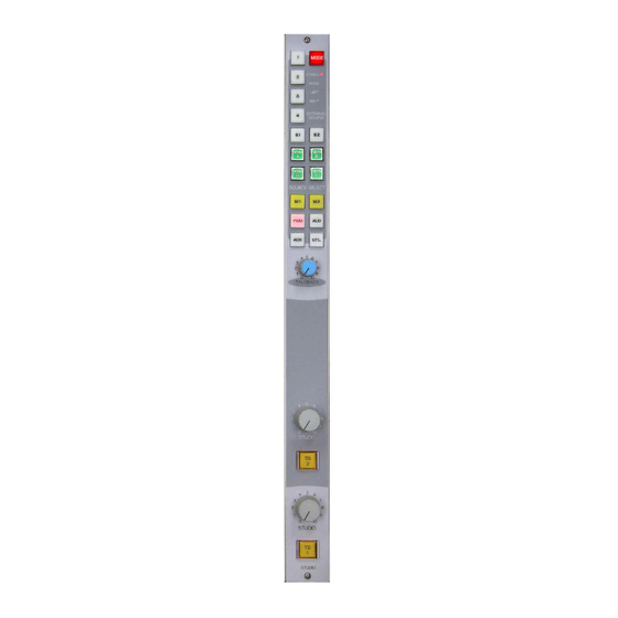
Page 59: Module Overview
MONO PANEL MXM C SWITCHES STUDIO SEND MXM D MONITOR DIP SW STU 1 MUTE STU 3 MUTE STU 2 MUTE STU 4 MUTE (TALLY 4) Studio Monitor Module Signal Flow Diagram page 6 – 2 A-7000 / Sep 2002... -
Page 60: Controls And Functions
Studio Mute Functions SW4 Position 4 – STUDIO 1 MUTE SW4 Position 3 – STUDIO 2 MUTE SW4 Position 2 – STUDIO 3 MUTE SW4 Position 1 – STUDIO 4 MUTE (TALLY 3) page 6 – 3 A-7000 / Sep 2002... -
Page 61: Hook-Ups
Pin 12 – Ext 1 Lt In LO Pin 11 – Ext 1 Rt In SH Pin 10 – Ext 1 Rt In HI Pin 23 – Ext 1 Rt In LO page 6 – 4 A-7000 / Sep 2002... -
Page 62: Connector - Talkback
Pin 1 – Talkback 2 Control Pin 2 – Talkback 2 Control Common Pin 3 – Studio 1 to Studio 2 Talkback Typical DB-9 Pin 6 – Studio 2 to Studio 1 Talkback connector page 6 – 5 A-7000 / Sep 2002... - Page 63 EXT 4 IN LEFT LOW EXT 4 IN LEFT HIGH EXT 4 IN RIGHT SHIELD EXT 4 IN RIGHT LOW EXT 4 IN RIGHT HIGH Lower DB-25 Connector Studio Control Module I/O Connector Pinouts page 6 – 6 A-7000 / Sep 2002...
- Page 64 M E T E R O U T P U T M O D U L E Meter Output Module (MO-7000) Chapter Contents Module Overview ................ 7-2 Flow Diagram ......................7-2 Internal Programming Options ..........7-3 Hook-ups ..................7-3 DB Connector Pinout Drawing ..........7-4 page 7 – 1 A-7000 / Sep 2002...
-
Page 65: Module Overview
(OPTIONAL) SWITCHED MONO SEND FRONT PANEL SWITCHES CUE/SOLO EXT1 EXT2 EXT1 MXM A MXM B EXT2 MXM C MXM D CUE LOGIC SOLO LOGIC METER MODULE Meter Output Module Signal Flow Diagram page 7 – 2 A-7000 / Sep 2002... -
Page 66: Internal Programming Options
Pin 3 – Ext 2 Lt In LO Pin 2 – Ext 2 Rt In SH Pin 1 – Ext 2 Rt In HI Pin 14 – Ext 2 Rt In LO Typical DB-25 connector page 7 – 3 A-7000 / Sep 2002... - Page 67 EXT 2 INPUT LEFT LOW EXT 2 INPUT LEFT HIGH EXT 2 INPUT RIGHT SHIELD EXT 2 INPUT RIGHT LOW EXT 2 INPUT RIGHT HIGH Lower DB-25 Connector Meter Output Module Connector Pinouts page 7 – 4 A-7000 / Sep 2002...
- Page 68 Cue Enable ......................8-4 Timer Restart ......................8-4 Hook-ups ..................8-5 Upper DB-25 Connector—Audio Inputs ..............8-5 Lower DB-25 Connector—Audio Outputs .............. 8-5 Lower DB-25 Connector—Control Connections ............ 8-6 DB Connector Pinout Drawing ..........8-7 page 8 – 1 A-7000 / Sep 2002...
-
Page 69: Module Overview
FEED SUM OF BACK CALLER FEEDS TO MULTITRACK LOCK ("MIC SUM") TO TRK 1 FET SW TRIM SUM OF CALLERS TO SUPERPHONE INPUT TRKS 3 & 4 Superphone Module Signal Flow Diagram page 8 – 2 A-7000 / Sep 2002... -
Page 70: Controls And Functions
When SW2 is ON, AUX assign operates independently of channel ON. Utility Enable When slide switch SW3 is OFF, UTL assign follows channel ON. When SW3 is ON, UTL assign operates independently of channel ON. page 8 – 3 A-7000 / Sep 2002... -
Page 71: Mics To Assign
When the module is turned ON, the console’s digital timer can be programmed to automatically reset to zero and begin counting up. SW11 position 7 activates timer restart when the phone module’s ON/START switch is pressed. page 8 – 4 A-7000 / Sep 2002... -
Page 72: Hook-Ups
Pin 20 – Feed To Hybrid 1 Out LO Pin 19 – Feed To Hybrid 2 Out SH Pin 18 – Feed To Hybrid 2 Out HI Pin 6 – Feed To Hybrid 2 Out LO page 8 – 5 A-7000 / Sep 2002... - Page 73 Typical DB-25 recording phone segments. connector When the RECORD READY switch is activated, pressing the module’s ON button generates a closure that can be used to start the machine in record mode. page 8 – 6 A-7000 / Sep 2002...
- Page 74 OUTPUT TO HYBRID 2 HI TAPE START/STOP COMMON TAPE START/STOP COMMON TAPE STOP TAPE STOP TAPE START TAPE START TAPE RECORD READY TAPE RECORD READY Lower DB-25 Connector Superphone Module I/O Connector Pinouts page 8 – 7 A-7000 / Sep 2002...
- Page 75 Flow Diagram ......................9-2 Internal Programming Options ............9-3 Hook-ups ..................9-3 Upper DB-25 Connector—Audio Inputs 1-4 ............. 9-3 Lower DB-25 Connector—Audio Inputs 5-8 ............. 9-3 DB-9 Connector—Audio Outputs ................9-4 DB Connector Pinout Drawing ............. 9-5 page 9 – 1 A-7000 / Sep 2002...
- Page 76 FRONT PANEL SWITCHES EXT1 EXT2 EXT3 EXT4 LOGIC EXT5 SOURCE SELECT LOGIC EXT6 EXT7 EXT8 PRESELECTOR Signal Flow Diagram page 9 – 2 A-7000 / Sep 2002...
-
Page 77: Upper Db-25 Connector-Audio Inputs
Pin 12 – Line 5 Lt In LO Pin 11 – Line 5 Rt In SH Pin 10 – Line 5 Rt In HI Pin 23 – Line 5 Rt In LO page 9 – 3 A-7000 / Sep 2002... -
Page 78: Connector-Audio Outputs
Pin 7 – Line Lt Out HI Pin 3 – Line Lt Out LO Pin 2 – Line Rt Out SH Pin 1 – Line Rt Out HI Pin 6 – Line Rt Out LO Typical DB-9 connector page 9 – 4 A-7000 / Sep 2002... - Page 79 LINE 8 LT IN LO LINE 8 LT IN HI LINE 8 RT IN SH LINE 8 RT IN LO LINE 8 RT IN HI Lower DB-25 Connector Line Selector Module I/O Connector Pinouts page 9 – 5 A-7000 / Sep 2002...
-
Page 80: Db Connector Pinout Drawing
T A P E R E M O T E M O D U L E Tape Remote Module (TR-7000; optional) Chapter Contents Module Overview ................10-2 DB Connector Pinout Drawings Full-Function Control I/O ....................10-3 START/STOP Function Control I/O .................. 10-4 page 10 – 1 A-7000 / Sep 2002... - Page 81 LED indicators in each switch function as tallyback indicators and are powered by the source machine. There are no internal connections between the tape remote panel and the console’s power rails. page 10 – 2 A-7000 / Sep 2002...
- Page 82 SW3 (FF) COMMON SW3 (FF) N.O. SW3 (FF) LED- SW3 (FF) LED+ SW2 (REW)COMMON SW2 (REW) N.O. SW2 (REW) LED- SW2 (REW) LED+ SW1 (RTZ) COMMON SW1 (RTZ) N.O. SW1 (RTZ)LED- SW1 (RTZ) LED+ page 10 – 3 A-7000 / Sep 2002...
- Page 83 SW3 (START) N.O. SW3 (START) LED- SW3 (START) LED+ SW2 (STOP) COMMON SW2 (STOP) N.O. SW2 (STOP) LED- SW2 (STOP) LED+ SW1 (START) COMMON SW1 (START) N.O. SW1 (START)LED- SW1 (START) LED+ page 10 – 4 A-7000 / Sep 2002...
- Page 84 M E T E R B R I D G E Meterbridge Chapter Contents Overview ..................11-2 Digital Timer ................11-2 Console Clock ................11-2 Controls ........................11-3 Setting the Time ....................... 11-3 Capacitor Backup ....................11-3 Operational Modes ....................11-3 page 11 – 1 A-7000 / Sep 2002...
-
Page 85: Overview
There are two basic parts to the clock: a main PCB containing the clock circuits and clock set controls (also may include capacitor backup) and a second PCB containing displays. Clock set controls may be accessed by opening the meterbridge cover. page 11 – 2 A-7000 / Sep 2002... -
Page 86: Controls
12/24 hour mode (Off - 12 hour, On - 24 hour). The clock can also be programmed to count in either 12 hour or 24 hour modes, controlled by SW3 position 4. page 11 – 3 A-7000 / Sep 2002... - Page 87 LED-1 Loaded Card ....................12-40 A7000-42 Frame ..................... 12-41 A7000-36 Frame ..................... 12-43 A7000-32 Frame ..................... 12-45 A7000-28 Frame ..................... 12-47 A7000-25 Frame ..................... 12-49 A-7000 Console ...................... 12-51 A-7000 Spare Parts Kit ................... 12-52 page 12 – 1 A-7000 / Sep 2002...
-
Page 88: Ml-7000 Main Pcb
YELLOW LED FOR R5 ON/OFF SWITCH 600031 PCB_IPS6000 PRINTED CIRCUIT BOARD 700049 PCB_SW2 700 PRINTED CIRCUIT BOARD 700688 4-40 X .375 HEX BRASS M/F SPACER 823034 440 X 3/16" HEX X 11/16" LONG S/Z MALE/FEMALE 823082 STANDOFF A-7000 / Sep 2002 page 12 - 2... - Page 89 YELLOW LED FOR R5 ON/OFF SWITCH 600031 PCB_IPS6000 PRINTED CIRCUIT BOARD 700049 PCB_SW2 700 PRINTED CIRCUIT BOARD 700688 4-40 X .375 HEX BRASS M/F SPACER 823034 440 X 3/16" HEX X 11/16" LONG S/Z MALE/FEMALE 823082 STANDOFF A-7000 / Sep 2002 page 12 - 3...
- Page 90 40.2 KOHM 1% .25W MC1206 RESISTOR 435039 CR1-CR3 10K POT, DUAL CONCENTRIC LINEAR, 12mm 500010 PAN POT DUAL 10K LINEAR POT, 1/8" SHAFT WITH DETENT 500023 388 SERIES DUAL 10K AUDIO CONCENTRIC W/LONG SEND POT 500062 SHAFT A-7000 / Sep 2002 page 12 - 4...
- Page 91 PRINTED CIRCUIT BOARD 700037 PCB_EQ/M6000 PRINTED CIRCUIT BOARD 700206 PCB_SW2 700 PRINTED CIRCUIT BOARD 700688 4-40 X .375 HEX BRASS M/F SPACER 823034 440 X 3/16" HEX X 11/16" LONG S/Z MALE/FEMALE 823082 STANDOFF A-7000 / Sep 2002 page 12 - 5...
- Page 92 C17, C18, C30, C31, C33-C44 CAPACITOR, 1µF 35V ELECTROLYTIC SMT TANTALUM 405005 TRIMMER CAPACITOR 410001 C2, C4, C6, C7, C48, C51, C56, C58, C60, C64, CAPACITOR, 10pF 100V CERAMIC SMT 415001 C73, C79, C80, C109, C117 A-7000 / Oct 2002 page 12 - 6...
- Page 93 515002 SW2-SW5, SW7-SW13, SW17-SW25 DPDT SMT SLIDE SWITCH 515003 PCB_ML6000SC PRINTED CIRCUIT BOARD SMT 700240 PEM FASTENERS 821009 HEATSINK FOR T-220 WITH MOUNTING PIN 825010 F1-F3 FUSE/ POLYSWITCH .3AMP SMT RESETABLE 835001 A-7000 / Oct 2002 page 12 - 7...
-
Page 94: 7000 Main Pcb
HIGH INTENSITY GREEN LED 600072 PCB_IPS6000 PRINTED CIRCUIT BOARD 700049 PCB_SW2 700 PRINTED CIRCUIT BOARD 700688 4-40 X .375 HEX BRASS M/F SPACER 823034 440 X 3/16" HEX X 11/16" LONG S/Z MALE/FEMALE 823082 STANDOFF A-7000 / Sep 2002 page 12 - 8... - Page 95 HIGH INTENSITY GREEN LED 600072 PCB_IPS6000 PRINTED CIRCUIT BOARD 700049 PCB_SW2 700 PRINTED CIRCUIT BOARD 700688 4-40 X .375 HEX BRASS M/F SPACER 823034 440 X 3/16" HEX X 11/16" LONG S/Z MALE/FEMALE 823082 STANDOFF A-7000 / Sep 2002 page 12 - 9...
- Page 96 2 POLE PUSHBUTTON SWITCH, ALTERNATE ACTION 510051 SW2-SW4 4 POLE PUSHBUTTON SWITCH, ALTERNATE ACTION 510085 A/AUD SWITCH LED PUSHBUTTON SWITCH GREEN LED/ NO CAP 510094 ON/PGM/CUE SWITCH LED PUSHBUTTON SWITCH RED LED/ NO CAP 510095 A-7000 / Oct 2002 page 12 - 10...
- Page 97 700341 PCB_SW2 700 PRINTED CIRCUIT BOARD 700688 4-40 X .625 RND NYLON 823013 4-40 X .375 HEX BRASS M/F SPACER 823034 440 X 3/16" HEX X 11/16" LONG S/Z MALE/FEMALE 823082 STANDOFF A-7000 / Oct 2002 page 12 - 11...
- Page 98 C2, C3, C5, C6, C15, C30, C52, C57, C60, C64, CAPACITOR, 10pF 100V CERAMIC SMT 415001 C65, C67, C73, C75, C83, C87, C88, C92, C96 C97, C100, C123, C124 CAPACITOR, 10pF 100V CERAMIC SMT 415001 A-7000 / Oct 2002 page 12 - 12...
- Page 99 SW1, SW2, SW4-SW8, SW10-SW16, SW18-SW26 DPDT SMT SLIDE SWITCH 515003 PCB_SL6000SF PRINTED CIRCUIT BOARD SMT 700242 PEM FASTENERS 821009 HEATSINK FOR T-220 WITH MOUNTING PIN 825010 F1-F3 FUSE/ POLYSWITCH .3AMP SMT RESETABLE 835001 A-7000 / Oct 2002 page 12 - 13...
- Page 100 220 OHM 5% .25W CARBON FILM RESISTOR 430214 R6, R7 (PCB_OMSW6000) 4.7 KOHM 5% .25W CARBON FILM RESISTOR 430233 R2, R4, R5, R8-R10, R12 (PCB_OMSW6000) 10 KOHM 5% .25W CARBON FILM RESISTOR 430239 A-7000 / Sep 2002 page 12 - 14...
- Page 101 DPDT SLIDE SWITCH 510082 PGM/AUX SWITCH CAP WHITE SWITCH CAP 530004 PCB_OMSW6000 PRINTED CIRCUIT BOARD 700141 PCB_OM/1_6000 PRINTED CIRCUIT BOARD 700142 PEM FASTENERS 821009 4-40 X .20 HEX BRASS M/F SPACER 823025 A-7000 / Sep 2002 page 12 - 15...
- Page 102 220 OHM 5% .25W CARBON FILM RESISTOR 430214 R6, R7 (PCB_OMSW6000) 4.7 KOHM 5% .25W CARBON FILM RESISTOR 430233 R2, R4, R5, R8-R10, R12 (PCB_OMSW6000) 10 KOHM 5% .25W CARBON FILM RESISTOR 430239 A-7000 / Sep 2002 page 12 - 16...
- Page 103 DPDT SLIDE SWITCH 510082 AUD/UTL SWITCH CAP WHITE SWITCH CAP 530004 PCB_OMSW6000 PRINTED CIRCUIT BOARD 700141 PCB_OM/2_6000 PRINTED CIRCUIT BOARD 700171 PEM FASTENERS 821009 4-40 X .20 HEX BRASS M/F SPACER 823025 A-7000 / Sep 2002 page 12 - 17...
-
Page 104: Cr-7000 Control Room Module
5.1V SMT ZENER DIODE C5V1 355002 D1, D3-D19 1N4148 FAST SWITCHING SMT DIODE 355003 U25-U29 74VHC4053 380008 C3, C5, C6, C8, C38, C41, C75, C76, C86, C87, C88 CAPACITOR, 22µF 25V ELECTROLYTIC SMT 405002 A-7000 / Sep 2002 page 12 - 18... - Page 105 10K DUAL AUDIO POT W/ 1/8" SHAFT 500026 1/MXMA/MXMB/MXMC/MXMD/AUD SWITCH PUSHBUTTON SWITCH GREEN LED/ NO CAP 510094 MODE/S1/S2/PGM/EQ IN SWITCH PUSHBUTTON SWITCH RED LED/ NO CAP 510095 2-4/M1/M2/AUX/UTL/REV SWITCH PUSHBUTTON SWITCH YELLOW LED/ NO CAP 510096 A-7000 / Sep 2002 page 12 - 19...
- Page 106 440 X 3/16" HEX X 11/16" LONG S/Z MALE/FEMALE 823082 STANDOFF U37, U42-U44 HEATSINK FOR T-220 WITHOUT MOUNTING PIN 825004 F1-F3, F13 FUSE/ POLYSWITCH .17 AMP RESETABLE 830043 F4-F12 FUSE/ POLYSWITCH .3AMP SMT RESETABLE 835001 A-7000 / Sep 2002 page 12 - 20...
-
Page 107: Sc-7000 Studio Control Module
C2-C4, C7, C8, C14, C16, C17, C21-C23, C27, C28, CAPACITOR, .1µF 50V MONOLITHIC CERAMIC 410005 C35, C36, C38-C43, C47, C49-C53, C56 C59, C64, C75, C76, C78, C80-C88, C91, C92, C94, CAPACITOR, .1µF 50V MONOLITHIC CERAMIC 410005 A-7000 / Oct 2002 page 12 - 21... - Page 108 OFF SW ORANGE TRANSP CAP WHITE BASE WHITE INS 530098 STEREO LED RED LED FOR R5 ON/OFF SWITCH 600027 LT/RT/TB1/TB2 LED YELLOW LED FOR R5 ON/OFF SWITCH 600031 MONO LED HIGH INTENSITY GREEN LED 600072 A-7000 / Oct 2002 page 12 - 22...
- Page 109 4-40 X .625 RND NYLON 823013 4-40 X .20 HEX BRASS M/F SPACER 823025 440 X 3/16" HEX X 11/16" LONG S/Z MALE/FEMALE 823082 STANDOFF HEATSINK FOR T-220 WITHOUT MOUNTING PIN 825004 A-7000 / Oct 2002 page 12 - 23...
- Page 110 R17, R18, R21, R22, R27-R30 10.0 KOHM 1% .25W MC1206 RESISTOR 435028 R19, R20 1.0 MOHM 5% .25W MC1206 RESISTOR 435049 PCB_SS6000 PRINTED CIRCUIT BOARD SMT 700279 F1, F2 FUSE/ POLYSWITCH .3AMP SMT RESETABLE 835001 A-7000 / Sep 2002 page 12 - 24...
-
Page 111: Mo-7000 Meter Output Module
100 OHM 5% .25W CARBON FILM RESISTOR 430212 R1, R3-R14, R21 220 OHM 5% .25W CARBON FILM RESISTOR 430214 330 OHM 5% .25W CARBON FILM RESISTOR 430215 470 OHM 5% .25W CARBON FILM RESISTOR 430216 A-7000 / Sep 2002 page 12 - 25... - Page 112 600004 PCB_MMS6000 PRINTED CIRCUIT BOARD 700072 PCB_UTS6000 PRINTED CIRCUIT BOARD 700129 PCB_MO6000 PRINTED CIRCUIT BOARD 700151 PEM FASTENERS 821009 4-40 X .375 HEX BRASS M/F SPACER 823034 FUSE/ POLYSWITCH 1.1AMP RESETABLE 830027 A-7000 / Sep 2002 page 12 - 26...
-
Page 113: Spn-7000 Superphone Module
C2, C3, C5, C6, C11, C12, C24, C26, C48-C57, C59, CAPACITOR, .1µF 50V MONOLITHIC CERAMIC 410005 C66-C70, C74-C82, C85, C88, C90, C91 C16-C21, C39, C40, C47, C58, C83, C84, C86, C87 CAPACITOR, 10pF 50V CERAMIC 410007 A-7000 / Oct 2002 page 12 - 27... - Page 114 OFF SW ORANGE TRANSP CAP WHITE BASE WHITE INS 530098 FADER 10K FADER,SINGLE AUDIO TAPER, 3000 SERIES 540020 RECTANGULAR RED DIFFUSED LED, TRANSPARENT READY LED 600001 SIDES ON-AIR LED RECTANGULAR RED LED 600004 A-7000 / Oct 2002 page 12 - 28...
- Page 115 700182 PCB_SW2-700 PRINTED CIRCUIT BOARD 700688 PEM FASTENERS 821009 4-40 X .20 HEX BRASS M/F SPACER 823025 4-40 X .20 HEX BRASS M/F SPACER 823082 HEATSINK FOR T-220 WITHOUT MOUNTING PIN 825004 A-7000 / Oct 2002 page 12 - 29...
- Page 116 R9-R15 220 OHM 5% .25W MC1206 RESISTOR 435009 R2-R6, R8 1.00 KOHM 1% .25W MC1206 RESISTOR 435015 R1, R7 4.99 KOHM 1% .25W MC1206 RESISTOR 435023 PCB_SL1X6000 PRINTED CIRCUIT BOARD SMT 700230 A-7000 / Sep 2002 page 12 - 30...
- Page 117 CAPACITOR, .22µF 50V CERAMIC SMT 415009 R11-R19 220 OHM 5% .25W MC1206 RESISTOR 435009 R1-R9 1.00 KOHM 1% .25W MC1206 RESISTOR 435015 4.99 KOHM 1% .25W MC1206 RESISTOR 435023 PCB_SPH2X6000 PRINTED CIRCUIT BOARD SMT 700233 A-7000 / Sep 2002 page 12 - 31...
- Page 118 PUSHBUTTON SWITCH RED LED/ NO CAP 510095 1-8 BUTTONS WHITE SWITCH CAP 530004 PCB_UTS6000 PRINTED CIRCUIT BOARD 700129 PCB_LS6000 PRINTED CIRCUIT BOARD 700179 PEM FASTENERS 821009 4-40 X .375 HEX BRASS M/F SPACER 823034 A-7000 / Sep 2002 page 12 - 32...
- Page 119 RTZ/FF/REW BUTTON WHITE SWITCH CAP 530004 REC BUTTON YELLOW SWITCH CAP 530005 PCB_UTS6000 PRINTED CIRCUIT BOARD 700129 PCB_TR6000 PRINTED CIRCUIT BOARD 700178 PEM FASTENERS 821009 4-40 X .375 HEX BRASS M/F SPACER 823034 A-7000 / Sep 2002 page 12 - 33...
- Page 120 STOP BUTTON GREEN SWITCH CAP 530001 START BUTTON YELLOW SWITCH CAP 530005 PCB_UTS6000 PRINTED CIRCUIT BOARD 700129 PCB_TR6000 PRINTED CIRCUIT BOARD 700178 PEM FASTENERS 821009 4-40 X .375 HEX BRASS M/F SPACER 823034 A-7000 / Sep 2002 page 12 - 34...
-
Page 121: Clock
R2-R8, R10, R26, R29, R30, R32, R33, R36 53.6 KOHM 1% .25W MC1206 RESISTOR 435060 R9, R12 100 KOHM 1% .25W MC1206 RESISTOR 435061 R11, R16, R17 10 MOHM 5% .25W MC1206 RESISTOR 435062 A-7000 / Sep 2002 page 12 - 35... - Page 122 4 POSITION SMT DIP SWITCH, TAPE SEALED 515001 GREEN SWITCH CAP 530001 CLEAR BUTTON WITH WHITE FRAME 530266 PCB_CLK220E PRINTED CIRCUIT BOARD SMT 700575 HEATSINK FOR T-220 WITHOUT MOUNTING PIN 825004 FUSE/ POLYSWITCH 1.0AMP SMT RESETABLE 835002 A-7000 / Sep 2002 page 12 - 36...
-
Page 123: Clock Display
220 OHM 5% .25W MC1206 RESISTOR 435009 R1, R4 22.1 KOHM 1% .25W MC1206 RESISTOR 435036 DS1-DS6 SINGLE DIGIT LED DISPLAY 610004 DS7-DS10 SINGLE SEGMENT GREEN LED DISPLAY 610018 PCB_CLD220D PRINTED CIRCUIT BOARD 700590 A-7000 / Aug 2003 page 12 - 37... - Page 124 220 OHM 5% .25W CARBON FILM RESISTOR 430214 410_PCB RT: R16 410_PCB RT: R1 330 OHM 5% .25W CARBON FILM RESISTOR 430215 410_PCB LT: R5, R9, R16 470 OHM 5% .25W CARBON FILM RESISTOR 430216 A-7000 / Sep 2002 page 12 - 38...
- Page 125 6-32 X 1.625 HEX ALUM. M/F 823019 #4 X 3/4" ALUMINUM HEX SPACER 823036 POWER SUPPLY HANDLE 824015 EXTRUDED ALUMINUM HEATSINK, L=8.25" 825011 CERAMIC FILM INSULATOR 825012 8 AMP CIRCUIT BREAKER 830001 FUSE/ POLYSWITCH .4AMP RESETABLE 830018 A-7000 / Sep 2002 page 12 - 39...
- Page 126 R5, R6 39 OHM 5% .25W MC1206 RESISTOR 435004 R1, R2 4.99 KOHM 1% .25W MC1206 RESISTOR 435023 DS1-DS8 HIGH INTENSITY YELLOW SMT LED VERTICAL 605013 PCB_LED1 PRINTED CIRCUIT BOARD SMT 700273 A-7000 / Sep 2002 page 12 - 40...
- Page 127 A-7000-42 FRAME PARTS LIST ITEM# DESCRIPTION CARD GUIDE BRACKET FOR A6000-42 001625 CARD GUIDE BRACKET FOR A6000-42 001629 CLK-70 LOADED CLK/TMR CARD 002749 FACEPLATE SIDE SHIM - A7000 003840 Clock/Timer Bracket for A7000 003847 FRAME PAN FOR A7000-42 003910 METER BRIDGE COVER FOR A7000-42 w/OVB...
- Page 128 A-7000-42 FRAME PARTS LIST ITEM# DESCRIPTION MALE SCREW RETAINER KIT 200035 MALE SCREW RETAINER KIT 200035 9 PIN HDE FEMALE SUBMINIATURE D CONNECT 200045 120 PIN CARDEDGE CONNECTOR FOR A6000 220023 120 PIN BOARD-TO-BOARD MALE CONNECTOR 220024 120 PIN BOARD-TO-BOARD FEMALE CONNECTOR...
- Page 129 A-7000-36 FRAME PARTS LIST ITEM# DESCRIPTION CARD GUIDE BRACKET FOR A6000-36 001496 HAT CHANNEL BRACKET FOR A6000-36 001498 CLK-70 LOADED CLK/TMR CARD 002749 FACEPLATE SIDE SHIM - A7000 003840 Clock/Timer Bracket for A7000 003847 METAL SIDEPLATE FOR A7000 003849 FRAME PAN FOR A7000-36...
- Page 130 A-7000-36 FRAME PARTS LIST ITEM# DESCRIPTION METAL PANEL MOUNT MILITARY CONNECTOR 230008 10 PIN PLUG 230020 3 PIN .098" PLUG FOR #26 AWG 230028 8 PIN DIP CONNECTOR 250010 DB9 PC MOUNT UP CONNECTOR 250032 RTS JACK 260005 VU METER...
- Page 131 A-7000-32 FRAME PARTS LIST ITEM# DESCRIPTION CARD GUIDE BRACKET FOR A6000-32 001475 HAT CHANNEL BRACKET FOR A6000-32 001477 CLK-70 LOADED CLK/TMR CARD 002749 FACEPLATE SIDE SHIM - A7000 003840 Clock/Timer Bracket for A7000 003847 METAL SIDEPLATE FOR A7000 003849 FRAME PAN FOR A7000-32...
- Page 132 A-7000-32 FRAME PARTS LIST ITEM# DESCRIPTION METAL PANEL MOUNT MILITARY CONNECTOR 230008 10 PIN PLUG 230020 3 PIN .098" PLUG FOR #26 AWG 230028 8 PIN DIP CONNECTOR 250010 DB9 PC MOUNT UP CONNECTOR 250032 RTS JACK 260005 VU METER...
- Page 133 A-7000-28 FRAME PARTS LIST ITEM# DESCRIPTION CARD GUIDE BRACKET FOR A6000-28 001615 HAT CHANNEL BRACKET FOR A6000-28 001639 CLK-70 LOADED CLK/TMR CARD 002749 FACEPLATE SIDE SHIM - A7000 003840 Clock/Timer Bracket for A7000 003847 METAL SIDEPLATE FOR A7000 003849 FRAME PAN FOR A7000-28...
- Page 134 A-7000-28 FRAME PARTS LIST ITEM# DESCRIPTION METAL PANEL MOUNT MILITARY CONNECTOR 230008 10 PIN PLUG 230020 3 PIN .098" PLUG FOR #26 AWG 230028 8 PIN DIP CONNECTOR 250010 DB9 PC MOUNT UP CONNECTOR 250032 RTS JACK 260005 VU METER...
- Page 135 A-7000-25 FRAME PARTS LIST ITEM# DESCRIPTION CARD GUIDE BRACKET FOR A6000-25 001605 HAT CHANNEL BRACKET FOR A6000-25 001628 CLK-70 LOADED CLK/TMR CARD 002749 FACEPLATE SIDE SHIM - A7000 003840 Clock/Timer Bracket for A7000 003847 METAL SIDEPLATE FOR A7000 003849 FRAME PAN FOR A7000-25...
- Page 136 A-7000-25 FRAME PARTS LIST ITEM# DESCRIPTION METAL PANEL MOUNT MILITARY CONNECTOR 230008 10 PIN PLUG 230020 3 PIN .098" PLUG FOR #26 AWG 230028 8 PIN DIP CONNECTOR 250010 DB9 PC MOUNT UP CONNECTOR 250032 RTS JACK 260005 VU METER...
-
Page 137: Psc-6008 Power Supply
A-7000 CONSOLE PARTS LIST ITEM# DESCRIPTION BK-500 SUPPORT UNIVERSAL BRACKET 001240 EXT-6000 RIBBON EXTENDER RIBBON 001392 ML-7000A MODULE 003800 SL-7000B MODULE 003801 SL-7000BN MODULE 003802 SL-7000BZ MODULE 003803 ML-7000AF MODULE 003804 OM-7000/1 MODULE 003805 OM-7000/2 MODULE 003806 MO-7000 MODULE 003807... - Page 138 PUSHBUTTON SWITCH GREEN LED/ NO CAP 510094 PUSHBUTTON SWITCH RED LED/ NO CAP 510095 PUSHBUTTON SWITCH YELLOW LED/ NO CAP 510096 RED LED FOR R5 ON/OFF SWITCH 600027 YELLOW LED FOR R5 ON/OFF SWITCH 600031 A-7000 / Sep 2002 page 12 - 52...
Need help?
Do you have a question about the A-7000 and is the answer not in the manual?
Questions and answers