
Related Manuals for Wheatstone Corporation D-9


Summary of Contents for Wheatstone Corporation D-9
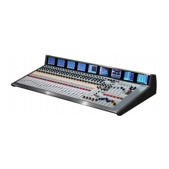
- Page 1 D-9 Digital Control Surface TECHNICAL MANUAL 600 Industrial Drive, New Bern, North Carolina, USA 28562...
- Page 2 D-9 Digital Control Surface Technical Manual - 1st Edition D-9 Digital Control Surface Technical Manual - 1st Edition D-9 Digital Control Surface Technical Manual - 1st Edition D-9 Digital Control Surface Technical Manual - 1st Edition D-9 Digital Control Surface Technical Manual - 1st Edition ©2003 Wheatstone Corporation...
- Page 3 This equipment must be installed and wired properly in order to assure compliance with FCC regulations. Caution! Any modifications not expressly approved in writing by Wheatstone could void the user's authority to operate this equipment. D-9 / Oct 2003...
- Page 4 IMPORTANT! Cleaning the Acrylic Surface An acrylic surface is a beautiful, lustrous material that is outstanding in durability and break resistance. With proper care, it will retain its attractive appearance for many years to come. This care should include precautions against scratching or contact with objects of high temperature that might mar the surface.
-
Page 5: Table Of Contents
Channel ON Switches ....................2-6 Fader ......................... 2-6 LCD Display ......................2-6 Input Level ......................2-7 Selected Source ....................2-7 Preset Source ...................... 2-7 Channel Status ....................2-7 Channel Number ....................2-7 page Contents – 1 D-9 / Oct 2003... - Page 6 Naming an Event ..................... 3-14 Control Modes ....................3-14 EQ Section ......................3-15 High-Pass Filter ....................3-15 Low-Pass Filter ....................3-15 Equalizer ......................3-16 Phase ....................... 3-16 Function Lock ....................... 3-16 page Contents – 2 D-9 / Jan 2006 D-9 / Oct 2003...
- Page 7 Chapter 6 - Host CPU (HC-9) Overview ..................6-2 HC-9 BIOS Settings/Format ............6-2 Ethernet IP Addressing ..............6-2 Ethernet Interface Wiring .............6-2 Mixer Link Wiring ................6-3 Internal Programming Options ............6-3 page Contents – 3 D-9 / Oct 2003 D-9 / Jan 2006...
- Page 8 Schematic ........................ 7-23 Load Sheet ....................... 7-26 HC-9 Host Controller Card Schematic ........................ 7-27 Load Sheet ....................... 7-34 BP-9 Back Plane Card Schematic ........................ 7-35 Load Sheet ....................... 7-36 page Contents – 4 D-9 / Jul 2009 D-9 / Oct 2003...
- Page 9 A Sample Example From The File ................A-7 A Second Example ....................A-8 An Example File - Complete..................A-9 Appendix 3 Replacement Parts List .............. A-14 Spare Parts Kit ................A-17 page Contents – 5 D-9 / Oct 2003 D-9 / Jan 2007...
- Page 10 Power Supply ................1-4 Failsafe Dual Redundant Supply ................1-5 Energizing ....................... 1-5 I/O Connections ................1-6 The Insulation Displacement Connector System ..........1- 6 Wiring Procedure - Double Connection to One Pin ..........1-8 page 1 – 1 D-9 / Oct 2003...
-
Page 11: Introduction
Designed to integrate flawlessly with the Wheatstone BRIDGE digital audio network router, the D-9 control surface allows you to easily create large or small platform-based systems that are exceptionally user-friendly and flexible. Wheat- stone BRIDGE network cages house all I/O ports and engine cards, and may be... -
Page 12: Control Surface Placement
The three available frame sizes dimensions (in inches) are shown in the drawings below. Do not connect the D-9 control surface to its power supply (and do not connect the power supply to the AC power line) until instructed to do so. -
Page 13: Power Supply
Rear view of the Rear view of the SPS-400 unit SPS-180 unit The D-9 control surface is powered by an SPS-180, or SPS-400 power supply installed in a Wheatstone Model PSR rackmount unit. Each PSR If failsafe redundant supplies have been ordered, you will houses up to four SPS-180, or up to two SPS-400 power supply units. -
Page 14: Failsafe Dual Redundant Supply
BOTH rackmount supplies powered up and connected to their associ- ated equipment. Energizing Assuming the D-9 control surface mainframe is properly placed, and its PSR power supply (or supplies) correctly rackmounted and connected to the control surface, you may now energize the PSR rackmount power supply by plugging it into the AC mains. -
Page 15: I/O Connections
G E N E R A L I N F O R M A T I O N I/O Connections All user wiring to and from the D-9 control surface is made via connectors located on the control surface’s rear panel. There are also two RJ-45 connectors for main (ENET A) and failsafe (ENET B - only used if the surface has a redundant CPU) ethernet connections. - Page 16 Note that mating hoods for each connector are also supplied with the system. These have locking screws that hold the connectors securely to their mates. page 1 – 7 D-9 / Oct 2003 D-9 / Jan 2006...
-
Page 17: Wiring Procedure - Double Connection To One Pin
4) A short piece of heatshrink tubing (pictured here before being slid into place) completes the connection. 5) Re-insert the pin into the DB-25 shell, spreading the vee apart to lock it in place. page 1 – 8 D-9 / Oct 2003... - Page 18 Channel ON Switches ..................... 2-6 Fader ........................2-6 LCD Display ......................2-6 Input Level ......................2-7 Selected Source ....................2-7 Preset Source ....................2-7 Channel Status ....................2-7 Channel Number ....................2-7 page 2 – 1 D-9 / Oct 2003...
-
Page 19: Controls And Functions
I N P U T P A N E L Input Panel (IS-D9) X Controllers Controls and Functions Each input panel of the D-9 digital audio control surface has four identical strips representing four input channels. Input Sources Each input panel controls four stereo sources. By... -
Page 20: Gain Control
The PHAN On/Off switch applies phantom voltage to any selected microphone. The phantom power attribute stays ON even when the microphone is not selected on the control surface. The D-9 Control Surface has (2) AUX encoders, (2) bank select switches (AUX 1/2 and AUX 3/4),... -
Page 21: Bus Minus
These 8 indicators (GROUPS) show which group(s) the channel has been assigned to using control switches in the BUS ASSIGN section of the EFS panel (page 3-5). The output assigns are accessed by means of the channel SET button. page 2 – 4 D-9 / Oct 2003... -
Page 22: Set Button
Channels are assigned to these DCMs in the following manner: press the channel SET button on the input fader section and then press the desired DCM SET assign button, located in the center of the EFS panel. page 2 – 5 D-9 / Oct 2003 D-9 / Jan 2006... -
Page 23: Pfl (Cue) Switch
NULL LED indicates which direction to move the fader to regain level control. Once the fader has been moved to the matching level the LED will turn off. The D-9 control surface can be ordered with optional touch sensitive, long-throw motorized faders for automated level control. LCD Display Each input section has an associated LCD display located above the input section in the control surface meterbridge. -
Page 24: Input Level
The bargraph itself consists of a moving “DOT” over a solid “COLUMN” where the “DOT” indicates the peak value of the signal, and the “COLUMN” indicates the average value. On the D-9 control surface the average value column has been set to VU timing characteristics. - Page 25 Modifying the Currently Selected Event ............. 3-14 Control Modes ....................3-14 EQ Section ....................... 3-15 High-Pass Filter ....................3-15 Low-Pass Filter ....................3-16 Equalizer ......................3-16 Phase ........................3-16 Function Lock ......................3-16 page 3 – 1 D-9 / Aug 2004 D-9 / Oct 2003...
-
Page 26: Controls And Functions
C O N T R O L P A N E L Control Panel (EFS-D9) Controls and Functions The D-9 digital audio control surface is equipped with one CONTROL panel. This panel contains MONITOR, BUS ASSIGN, AFL/PFL, SOLO, TALKBACK, EQ, 5,1... -
Page 27: Control Room Section
SPKR A, SPKR B - these two switches are used to determine which of two outputs will be fed by the CR signal. Each feed may have its mode pro- grammed separately (see Selecting Output Mix Destinations on page 3-11). page 3 – 3 D-9 / Oct 2003 D-9 / Jan 2007... -
Page 28: Studio Section
DIM BUTTON - lets the operator “dim” the headphone output signal (drop in level). Actual DIM level is set by the DIM encoder at the top of this panel. page 3 – 4 D-9 / Oct 2003... -
Page 29: Mode Control And Indicators
SUR/CTR, and CTR/LFE knobs. The meterbridge display will also show a multi-color graphic representation of this system. The system can generate 5.1 signals from MONO or STEREO sources, and can modify the 5.1 signal of existing 5.1 input sources. page 3 – 5 D-9 / Oct 2003... -
Page 30: Solo(Afl)/Mute/Dim/Cue(Pfl) Section
TB signal. The dim defeat switch allows for temporarily overriding the attenuation to bring all DIMmed signals back to their normal level. page 3 – 6 D-9 / Oct 2003 D-9 / Jan 2007... -
Page 31: Clear Afl/Pfl
SET button will illuminate, and the current mode setting for that channel will be displayed on the MODE switches. MODE can be reconfigured by pressing any allowable button. page 3 – 7 D-9 / Oct 2003 D-9 / Jan 2006... -
Page 32: Aux/Mxm Master Outputs
SET button of the target module you wish to copy to. It will begin to flash in concert with the PASTE button, and the TAKE button will light. To accomplish the copy, press the TAKE button. page 3 – 8 D-9 / Oct 2003... -
Page 33: To Copy Groups
Then press the PASTE button and the target channel SET buttons, which will flash in concert with the PASTE button. To execute, press the TAKE button. page 3 – 9 D-9 / Oct 2003... -
Page 34: To Copy One To All
The HOLD button allows you to hold the display for a longer viewing duration, while still allowing the counter to continue in the background. Releasing the button will then display the current count. page 3 – 10 D-9 / Oct 2003... -
Page 35: Time Of Day Clock
EXAMPLE: An example might be a MXM feed routed to several listeners participating in the program, or an AUD bus routed to multiple recording devices. page 3 – 11 D-9 / Aug 2004 D-9 / Oct 2003 D-9 / Jan 2006... -
Page 36: Changing Output Mix Destinations
To overwrite an existing event with the current settings, turn the PREVIEW SCROLL knob until the desired event is displayed in the PRO- GRAM/PREVIEW window, then quickly press MODIFY, then SAVE. page 3 – 12 D-9 / Dec 2004 D-9 / Oct 2003... -
Page 37: Taking An Event
Pressing the PREVIEW button a second time will cancel the preview. It should be noted that no audio signals are changed in any way by the preview feature. page 3 – 13 D-9 / Dec 2004 D-9 / Oct 2003... -
Page 38: Event Default Button
Control Modes The D-9 control surface is operated in one of three modes. In Administrator mode access is allowed to all surface functions. In User mode a limited set of user functions is allowed. The set of functions allowed in User mode is set independently for each console using the Bridge XPoint software (see the Bridge Router manual for details). -
Page 39: Eq Section
(air-conditioning rumble, line hum, traffic or footstep impacts) with minimal effect on the required program. page 3 – 15 D-9 / Dec 2004 D-9 / Oct 2003... -
Page 40: Low-Pass Filter
EFS panel. The control surface operator can lock out functions that may be undesirable to accidentally activate. To lock out a function, first press the FUNCTION LOCK button. This causes the page 3 – 16 D-9 / Aug 2004 D-9 / Oct 2003 D-9 / Jan 2006... - Page 41 If you fail to press the FUNCTION LOCK button within about five seconds of pressing the locked control, the operation will time out and the control will remain locked. page 3 – 17 D-9 / Aug 2004 D-9 / Oct 2003...
- Page 42 Groups Output Display ..................4-5 DCM Group Displays ..................4-5 ON (G1-G8) Switch ................... 4-6 PFL (Cue) ......................4-6 AFL (Solo) ......................4-6 Submix (Group) Faders ..................4-6 Page Buttons ......................4-6 page 4 – 1 D-9 / Oct 2003...
-
Page 43: Controls And Functions
M A S T E R P A N E L Master Panel (MFS-D9) Controls and Functions The D-9 digital audio control surface is equipped with one MASTER panel. This panel houses four master pro- gram outputs and eight submixes group outputs. -
Page 44: Master Mix Destinations
EQ section of the EFS panel. When any knob of the EQ section is rotated, the LCD displays a graphical representation of the EQ settings. EFS-D9 Panel page 4 – 3 D-9 / Oct 2003... -
Page 45: Dcm Master Displays
The lit NULL LED indicates which direction to move the fader to regain level control. Once the fader has been moved to the matching level the LED will turn off. page 4 – 4 D-9 / Oct 2003... -
Page 46: Submixes (Groups) Outputs
DCMS display group. Channels are assigned to these DCMs by pressing the group’s SET button and then pressing the desired DCM ASSIGN button, located in the EFS-D9 panel. page 4 – 5 D-9 / Oct 2003... -
Page 47: On (G1-G8) Switch
A mode, the PAGE B button places all input channels in B Mode, and the FLIP ALL button toggles each individual input channel page button to its opposite state (i.e., A becomes B, B becomes A). Useful for instant LIVE to BREAK setups. page 4 – 6 D-9 / Oct 2003... - Page 48 Ratio ........................5-4 Release ......................5-4 Makeup Gain ..................... 5-4 MXM Confidence Feed ................... 5-4 Talkback Preselects ....................5-5 Display Buttons ....................... 5-6 Programmable Buttons ................... 5-6 Mute Groups ......................5-7 Fader ........................5-7 page 5 – 1 D-9 / Oct 2003...
-
Page 49: Controls And Functions
This panel also contains the MXM confidence feed section, the talkback preselects section, the display buttons, the program- mable buttons and the DCM section. Compressor/Limiter The compressor algorithm used in the D-9 control surface is designed to: - allow smooth, inaudible, and unobtrusive level control on uneven sources;... -
Page 50: Dyn In
This control determines how quickly (between nominally 0.1mS and 330mS) the compressor reacts to signals. Faster attack times result in “tighter” and more obvious control; longer attack times lend them- selves well to gentler automatic volume control. page 5 – 3 D-9 / Oct 2003... -
Page 51: Ratio
SOURCE display, at which time the TAKE button will light. Pressing that TAKE button will now program the corresponding MXM to receive the selected source. Repeat page 5 – 4 D-9 / Oct 2003... -
Page 52: Talkback Preselects
When EVENTS are stored, the four TB preselects as displayed at the time of the EVENT SAVE action will be also stored and can be recalled with that EVENT. DCM-D9 Panel EFS-D9 Panel page 5 – 5 D-9 / Oct 2003... -
Page 53: Display Buttons
Logic card output ports, and the LEDs on the Spare buttons may also be lit by a remote device connected to a Logic card input port. See the Bridge Router manual for details. page 5 – 6 D-9 / Aug 2004 D-9 / Oct 2003... -
Page 54: Mute Groups
The lit NULL LED indicates which direction to move the fader to regain level control. Once the fader has been moved to the matching level the LED will turn off. page 5 – 7 D-9 / Oct 2003... - Page 55 Typical Crossover Cable ............6-5 Optical Fiber Interface ............... 6-6 Optical Transceiver ....................6-6 Connectors Type ....................6-6 Optical Fiber Cable ....................6-6 HC-9 Pinouts Drawing ............... 6-7 page 6 – 1 D-9 / Jul 2009 D-9 / Jan 2006...
-
Page 56: Overview
Keyboard, floppy controller and video ports are for factory use only. The purpose of the host controller is to provide control of the D-9 control surface. The HC-9 communicates to the XPoint Configuration PC via TCP/IP over Ethernet through a standard ethernet hub or switch. It also communicates to the Bridge Router system via a special mixer link connection. -
Page 57: Mixer Link Wiring
44.1kHz and on for a sample rate of 48kHz. set to the same sample rate! SW12 Position 2 - Not Used This dipswitch position is reserved for future use. page 6 – 3 D-9 / Jul 2009 D-9 / Jan 2006... -
Page 58: Sw12 Position 3 - Redundant Cpu
Pin 2 – TXD - Pin 3 – RXD + Pin 4 – N/C Pin 5 – N/C Pin 6 – RXD - Pin 7 – N/C Pin 8 – N/C page 6 – 4 D-9 / Mar 2008 D-9 / Jan 2006... - Page 59 RXD - Orange Green RXD + TXD + White/Green White/Orange RJ-45 RJ-45 Plug Blue Blue Plug White/Blue White/Blue RXD - TXD - Green Orange White/Brown White/Brown Brown Brown SED FOR MIXER LINK CONNECTOR page 6 – 5 D-9 / Jan 2006...
-
Page 60: Optical Fiber Interface
Optical Fiber Interface The D-9 control surface supports an optional fiber con- nection to the Bridge Router. The D-9 surface uses an SFP module interface with integral LC connectors. Note that the QOT-2001 rear panel on the Bridge router uses SC connec- tors, so a patch cable fitted with LC connectors on one end and SC connectors on the other end is required. - Page 61 LN LED LN LED LK LED LK LED Mixer Link Connections CAT5 Optional Optical Connector FIBER (RJ-45) (LC Connector) TXD + TXD - RXD + (crossover) RXD - page 6 – 7 D-9 / Mar 2008 D-9 / Jan 2006...
-
Page 62: Schematic
VU-9 VU Receiver Card Schematic ........................ 7-41 Load Sheet ....................... 7-42 SW1-700 Switch Card Schematic ........................ 7-43 Load Sheet ....................... 7-44 PWI-5.1 Power Interface Card Schematic ........................ 7-45 Load Sheet ....................... 7-46 page 7 – 1 D-9 / Oct 2003... - Page 63 D-9/May 2005 page 7 - 2...
- Page 64 7 - 3 D-9/May 2005...
- Page 65 D-9/May 2005 page 7 - 4...
- Page 66 D-9/May 2005 page 7 - 5...
- Page 67 7 - 6 D-9/May 2005...
- Page 68 7 - 7 D-9/May 2005...
- Page 69 IP-9 4 Inputs Panel Switch Card Load Sheet page 7 – 8 D-9 / May 2005...
- Page 70 7 - 9 D-9 / Oct 2003...
- Page 71 S C H E M A T I C D R A W I N G S IQ-9 IQ Card Load Sheet page 7 – 2 page 7 – 10 D-9 / Oct 2003...
- Page 72 D-9 / Oct 2003 page 7 - 11...
- Page 73 7 - 12 D-9 / Oct 2003...
- Page 74 7 - 13 D-9 / Oct 2003...
- Page 75 7 - 14 D-9 / Oct 2003...
- Page 76 7 - 15 D-9 / Oct 2003...
- Page 77 MN-9 Control Panel Switch Card Load Sheet page 7 – 16 D-9 / Oct 2003...
- Page 78 D-9/May 2005 page 7 - 17...
- Page 79 7 - 18 D-9/May 2005...
- Page 80 MFS-9 4 Master Panel Switch Card Load Sheet page 7 – 19 D-9 / May 2005...
- Page 81 New Bern, NC 28562 CHECKED 0.1uF 0.1uF 0.1uF 0.1uF 0.1uF 0.1uF 0.1uF 0.1uF 0.1uF 0.1uF 0.1uF 0.1uF 0.1uF L293DD ISSUED SIZE FSCM NO. DWG. NO. 84S0146 W# 700752 IQO-9A PCB 1 OF 2 SCALE SHEET page 7 - 20 D-9/May 2005...
- Page 82 11-5-03 600 Industrial Drive LM317 LM317 LM317 New Bern, NC 28562 0.1uF 0.1uF 0.1uF CHECKED +G56 +G12 +M12 ISSUED SIZE FSCM NO. DWG. NO. 84S0147 W# 700752 IQO-9A PCB 2 OF 2 SCALE SHEET page 7 - 21 D-9/May 2005...
- Page 83 S C H E M A T I C D R A W I N G S IQO-9 Master Panel IQ Card Load Sheet page 7 – 3 page 7 – 22 D-9 / Oct 2003 D-9 / May 2005...
- Page 84 7 - 23 D-9 / Oct 2003...
- Page 85 7 - 24 D-9 / Oct 2003...
- Page 86 7 - 25 D-9 / Oct 2003...
- Page 87 DCM-9 DCM Panel Switch Card Load Sheet page 7 – 26 D-9 / Oct 2003...
- Page 88 10.0K 0.01uF 0.1uF 0.1uF 0.1uF 0.1uF ____ R191 1.00K BP_BD_ID[7]_U R208 10.0K BP_BD_ID[7]_L 1.00K BP_BD_ID[7]_M ISSUED SIZE FSCM NO. DWG. NO. 84S0193-1 XC18V04 W# 700740 HC-9E PCB 1 OF 7 SCALE SHEET page 7 - 27 D-9 / Apr 2008...
- Page 89 8-6-07 600 Industrial Drive New Bern, NC 28562 C250 C249 CHECKED 0.1uF 0.1uF 0.01uF 0.01uF 0.01uF ISSUED SIZE FSCM NO. DWG. NO. 84S0193-2 W# 700740 HC-9E PCB 2 OF 7 SCALE SHEET page 7 - 28 D-9 / Apr 2008...
- Page 90 C183 C185 CHECKED FIB2_RX+ 0.01uF 0.01uF 0.01uF 0.01uF 0.01uF 0.01uF 0.01uF 0.01uF 0.01uF 0.01uF 0.01uF 0.01uF ISSUED SIZE FSCM NO. DWG. NO. 84S0193-3 W# 700740 HC-9E PCB 3 OF 7 SCALE SHEET page 7 - 29 D-9 / Apr 2008...
- Page 91 2.5V 0.1uF 100uF 47uF 0.01uF 0.01uF 0.01uF 0.01uF 0.01uF 0.01uF 0.01uF 0.01uF 0.01uF 0.01uF 0.01uF 0.01uF ISSUED SIZE FSCM NO. DWG. NO. 84S0193-4 W# 700740 HC-9E PCB 4 OF 7 SCALE SHEET page 7 - 30 D-9 / Apr 2008...
- Page 92 2.5V 0.1uF 100uF 47uF 0.01uF 0.01uF 0.01uF 0.01uF 0.01uF 0.01uF 0.01uF 0.01uF 0.01uF 0.01uF 0.01uF 0.01uF ISSUED SIZE FSCM NO. DWG. NO. 84S0193-5 W# 700740 HC-9E PCB 5 OF 7 SCALE SHEET page 7 - 31 D-9 / Apr 2008...
- Page 93 47uF 0.01uF 0.01uF 0.01uF 0.01uF 0.01uF 0.01uF 0.01uF 0.01uF 0.01uF 0.01uF 0.01uF 0.01uF 0.01uF 0.01uF 0.01uF ISSUED SIZE FSCM NO. DWG. NO. 84S0193-6 W# 700740 HC-9E PCB 6 OF 7 SCALE SHEET page 7 - 32 D-9 / Apr 2008...
- Page 94 - SA UR US - Sergey Averin - +5_LCD_SW_2 APPROVALS DATE +5_LCD_SW_3 DRAWN 8-6-07 600 Industrial Drive New Bern, NC 28562 1.00K 1.00K 1.00K CHECKED ISSUED SIZE FSCM NO. DWG. NO. 84S0193-7 W# 700740 HC-9E PCB 7 OF 7 SCALE SHEET page 7 - 33 D-9/Aug 2007...
- Page 95 HC-9 Host Controller Card Load Sheet page 7 – 34 D-9 / Apr 2008...
- Page 96 7 - 35 D-9 / Oct 2003...
- Page 97 BP-9 Back Plane Card Load Sheet page 7 – 36 D-9 / Oct 2003...
- Page 98 7 - 37 D-9 / Oct 2003...
- Page 99 S C H E M A T I C D R A W I N G S BPR-9 Back Plane Repeater Card Load Sheet page 7 – 4 page 7 – 38 D-9 / Oct 2003...
- Page 100 7 -39 D-9 / Oct 2003...
- Page 101 S C H E M A T I C D R A W I N G S 32VC5-5 +5V DC to DC Converter Card Load Sheet page 7 – 5 page 7 – 40 D-9 / Oct 2003...
- Page 102 7 - 41 D-9 / Oct 2003...
- Page 103 S C H E M A T I C D R A W I N G S VU-9 VU Receiver Card Load Sheet page 7 – 6 page 7 – 42 D-9 / Oct 2003...
- Page 104 7 - 43 D-9 / Oct 2003...
- Page 105 S C H E M A T I C D R A W I N G S SW1-700 Switch Card - Load Sheet page 7 – 7 page 7 – 44 D-9 / Oct 2003...
- Page 106 7 - 45 D-9 / Oct 2003...
- Page 107 S C H E M A T I C D R A W I N G S PWI-5.1 Power Interface Card Load Sheet page 7 – 8 page 7 – 46 D-9 / Oct 2003...
- Page 108 Modifying The Options Text File................A-6 A Sample Example From The File ................A-7 A Second Example ....................A-8 An Example File - Complete..................A-9 Appendix 3 Replacement Parts List .............. A-14 Spare Parts Kit ................A-17 page A – 1 D-9 / Jan 2007...
- Page 109 A P P E N D I C E S Appendix 1 Contents Control Surface Clock ..............A-3 Setting the Time ......................A-3 Update Options ......................A-3 Synchronize ......................A-3 Battery Backup ......................A-4 page A – 2 D-9 / Jan 2007...
-
Page 110: Control Surface Clock
The Options form gives you different auto update options. Select the appropriate option for your application. Synchronize For the best accuracy synchronize the PC’s clock to a master clock system. Refer to your master clock documentation for more information. page A – 3 D-9 / Jan 2007... -
Page 111: Battery Backup
(it will do this for 3 to 4 weeks). To activate battery backup of the control surface’s clock simply pull out the yellow strip from the HC-9 board, as shown on the picture below. page A – 4 D-9 / Jan 2007... - Page 112 Options Text File ................A-6 Introduction ....................... A-6 Modifying The Options Text File ................A-6 A Sample Example From The File ................A-7 A Second Example ....................A-8 An Example File - Complete ..................A-9 page A – 5 D-9 / Jan 2007...
-
Page 113: Options Text File
Options Text File Introduction There are a number of operational features on the D-9 surface that are controlled by the contents of the Options Text File (D9_OPTS.TXT) that resides on the surface's flash drive. In order to configure these features it is necessary to modify this file. - Page 114 The edited line must follow the established syntax precisely or the surface may not behave as expected. page A – 7 D-9 / Jan 2007...
-
Page 115: A Second Example
You may have fewer or greater modes available depending on the surface model and vintage. In any event you can select the same or a different mode from the available modes for each programmable button on the surface. page A – 8 D-9 / Jan 2007... -
Page 116: An Example File - Complete
4 = Automation, Button & LED are controlled by automation interface 5 = Preset Select, Button selects pre-configured preset, LED controlled by Surface SPARE1:2 SPARE2:2 SPARE3:2 SPARE4:2 SPARE5:2 SPARE6:2 SPARE7:2 SPARE8:2 SPARE9:2 SPARE1Ø:2 SPARE11:2 SPARE12:2 page A – 9 D-9 / Jan 2007... - Page 117 DIRECT_OUT9:Ø DIRECT_OUT1Ø:Ø DIRECT_OUT11:Ø DIRECT_OUT12:Ø DIRECT_OUT13:Ø DIRECT_OUT14:Ø DIRECT_OUT15:Ø DIRECT_OUT16:Ø DIRECT_OUT17:Ø DIRECT_OUT18:Ø DIRECT_OUT19:Ø DIRECT_OUT2Ø:Ø DIRECT_OUT21:Ø DIRECT_OUT22:Ø DIRECT_OUT23:Ø DIRECT_OUT24:Ø DIRECT_OUT25:Ø DIRECT_OUT26:Ø DIRECT_OUT27:Ø DIRECT_OUT28:Ø DIRECT_OUT29:Ø DIRECT_OUT3Ø:Ø DIRECT_OUT31:Ø DIRECT_OUT32:Ø DIRECT_OUT33:Ø DIRECT_OUT34:Ø DIRECT_OUT35:Ø DIRECT_OUT36:Ø DIRECT_OUT37:Ø DIRECT_OUT38:Ø DIRECT_OUT39:Ø DIRECT_OUT4Ø:Ø page A – 10 D-9 / Jan 2007...
- Page 118 // or Ø-9 LCD panel for rightmost popup (Ø right most LCD). POPUP_BASE_LCD:-1 // Syntax: SURROUND_UNFOLD:? // ? Ø = disable surround unfold // ? 1 = (default) enable surround unfold SURROUND_UNFOLD:1 page A – 11 D-9 / Jan 2007...
- Page 119 1 = supress machine start/stop DIOs when input channels on/off via ACI. 2 = supress machine start/stop DIOs when input channels on/off via remote on/off DIO . 3 = supress machine start/stop DIOs when input channels on/off via ACI and/or DIO. ACI_DISABLE_MSS:Ø page A – 12 D-9 / Jan 2007...
-
Page 120: Appendix 3
Spare Parts Kit ................A-17 For the most part there are no user-replaceable parts in the D-9 control surface. Exceptions are those controls and components that in the course of normal use may need maintenance (i.e., faders, pots, ON/ OFF switches, etc.). A complete list of available components is shown on the next page. - Page 121 A P P E N D I C E S REPLACEMENT PARTS — D-9 CONTROL SURFACE COMPONENT DESCRIPTION WS P/N IS-D9 PANEL COMPLETE INPUT PANEL WITH STANDARD FADERS "005214" IS-D9M PANEL COMPLETE INPUT PANEL WITH MOTORIZED FADERS "005210" EFS-D9 PANEL COMPLETE CONTROL PANEL "005211"...
- Page 122 A P P E N D I C E S REPLACEMENT PARTS — D-9 CONTROL SURFACE COMPONENT DESCRIPTION WS P/N REPLACEMENT FADER ASSEMBLY WIRED NON-MOTORIZED FADER "005296" REPLACEMENT FADER ASSEMBLY WIRED MOTORIZED FADER "005297" REPLACEMENT FADER KNOB BLACK FADER KNOB "520001"...
- Page 123 A P P E N D I C E S REPLACEMENT PARTS — D-9 CONTROL SURFACE COMPONENT DESCRIPTION WS P/N LUMA BUTTON STYRENE WITH UV INHIBITOR BUTTON PRINTED "1" "530297" LUMA BUTTON STYRENE WITH UV INHIBITOR BUTTON PRINTED "2" "530298"...
- Page 124 A P P E N D I C E S SPARE PARTS KIT — D-9 CONTROL SURFACE W# 055275 w/NON-MOTORIZED FADER W# 055276 w/MOTORIZED FADER COMPONENT DESCRIPTION WS P/N SW1-700/RED LOADED CARD LOADED SWITCH CARD "001977" EI-5.1 LOADED CARD ENCODER LOADED CARD "005030"...
Need help?
Do you have a question about the D-9 and is the answer not in the manual?
Questions and answers