
Related Manuals for Wheatstone Corporation D-5.1


Summary of Contents for Wheatstone Corporation D-5.1
- Page 1 D-5.1 Digital Television Control Surface TECHNICAL MANUAL 600 Industrial Drive, New Bern, North Carolina, USA 28562...
- Page 2 D-5.1 Digital Television Control Surface Technical Manual - 1st Edition D-5.1 Digital Television Control Surface Technical Manual - 1st Edition D-5.1 Digital Television Control Surface Technical Manual - 1st Edition D-5.1 Digital Television Control Surface Technical Manual - 1st Edition D-5.1 Digital Television Control Surface Technical Manual - 1st Edition...
- Page 3 This equipment must be installed and wired properly in order to assure compliance with FCC regulations. Caution! Any modifications not expressly approved in writing by Wheatstone could void the user's authority to operate this equipment. D-5.1 / Sep 2003...
- Page 4 IMPORTANT! Cleaning the Acrylic Surface An acrylic surface is a beautiful, lustrous material that is outstanding in durability and break resistance. With proper care, it will retain its attractive appearance for many years to come. This care should include precautions against scratching or contact with objects of high temperature that might mar the surface.
-
Page 5: Table Of Contents
AFL (Solo) ......................... 2-7 Dynamics ........................2-7 EQ ..........................2-8 Output Assign Displays .................... 2-8 Channel ON Switches ....................2-8 DCM Displays ......................2-9 VU ..........................2-9 GR ..........................2-9 Fader ......................... 2-9 page Contents – 1 D-5.1 / Sep 2003... - Page 6 Modifying the Currently Selected Event ............. 4-10 Deleting an Event ....................4-11 Previewing an Event ................... 4-11 Event Default Button ................... 4-11 Establishing the Default Setting ................. 4-11 Naming an Event ....................4-11 page Contents – 2 D-5.1 / Dec 2004 D-5.1 / Sep 2003...
- Page 7 Mixer Link Wiring ................6-3 Internal Programming Options ............6-3 Switch Settings ................6-3 SW5-SW8 - CAT5 vs. Fiber & Transceiver Select ............6-3 SW9 - Master Reset ....................6-3 page Contents – 3 D-5.1 / Mar 2008 D-5.1 / Sep 2003 D-5.1 / Jan 2006...
- Page 8 DCM-5.1 Dynamics Fader Panel Switch Card Schematic ........................ 7-47 Load Sheet ....................... 7-50 HC-5.1 Host Controller Card Schematic ........................ 7-51 Load Sheet ....................... 7-57 page Contents – 4 D-5.1 / Jul 2009 D-5.1 / Jan 2006 D-5.1 / Sep 2003...
- Page 9 Modifying The Options Text File................A-3 A Sample Example From The File ................A-4 A Second Example ....................A-5 An Example File - Complete..................A-6 Appendix 2 Replacement Parts List ............... A-9 page Contents – 5 D-5.1 / Sep 2003 D-5.1 / Jan 2007...
- Page 10 Power Supply ................1-4 Failsafe Dual Redundant Supply ................1-5 Energizing ....................... 1-5 I/O Connections ................1-6 The Insulation Displacement Connector System ..........1- 6 Wiring Procedure - Double Connection to One Pin ..........1-8 page 1 – 1 D-5.1 / Sep 2003...
-
Page 11: Introduction
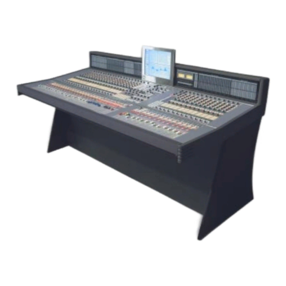
Wheatstone’s proven BRIDGE tech- nology. Designed to integrate flawlessly with the Wheatstone BRIDGE digital audio network router, the D-5.1 control surface allows you to easily create large or small platform-based systems that are exceptionally user- friendly and flexible. -
Page 12: Control Surface Placement
29-30 inches from the floor. The D-5.1 control surface 4-bay frame size is shown below. Do not connect the D-5.1 control surface to its power supply (and do not connect the power supply to the AC power line) until instructed to do 16-3/4"... -
Page 13: Power Supply
Rear view of the Rear view of the SPS-400 unit SPS-180 unit The D-5.1 control surface is powered by an SPS-180, SPS-400 or SPS-40 power supply installed in a Wheatstone Model PSR rackmount If failsafe redundant sup- plies have been ordered, unit. -
Page 14: Failsafe Dual Redundant Supply
BOTH rackmount supplies powered up and connected to their associ- ated equipment. Energizing Assuming the D-5.1 control surface mainframe is properly placed, and its PSR power supply (or supplies) correctly rackmounted and connected to the control surface, you may now energize the PSR rackmount power supply by plugging it into the AC mains. -
Page 15: I/O Connections
G E N E R A L I N F O R M A T I O N I/O Connections All user wiring to and from the D-5.1 control surface is made via connectors located on the control surface’s rear panel. There are two RJ-45 connectors for main and failsafe ethernet connections. - Page 16 Note that mating hoods for each connector are also supplied with the system. These have locking screws that hold the connectors securely to their mates. page 1 – 7 D-5.1 / Sep 2003 D-5.1 / Jan 2006...
-
Page 17: Wiring Procedure - Double Connection To One Pin
4) A short piece of heatshrink tubing (pictured here before being slid into place) completes the connection. 5) Re-insert the pin into the DB-25 shell, spreading the vee apart to lock it in place. page 1 – 8 D-5.1 / Sep 2003... - Page 18 AFL (Solo) ....................... 2-7 Dynamics ........................ 2-7 EQ ........................... 2-8 Output Assign Displays ..................2-8 Channel ON Switches ..................... 2-8 DCM Displays ......................2-9 VU ........................... 2-9 GR ........................... 2-9 Fader ........................2-9 page 2 – 1 D-5.1 / Sep 2003...
-
Page 19: Controls And Functions
Input Section (IS-D5.1 & IFS-5.1) Controls and Functions Each input section of the D-5.1 digital audio control surface consist of two panels (IS-5.1 and IFS-5.1with non-motorized faders, or IFSM-5.1 with motorized faders), and has four identical strips representing four input channels. -
Page 20: Aux
AUX 1 status for that channel. Remember, changing the global settings for an AUX send will reprogram all channels to follow the global setting for that AUX, overriding any individual programming. page 2 – 3 D-5.1 / Sep 2003... -
Page 21: Mode Selector
Solo TB-5.1 Panel A SOLO switch allows the operator to solo monitor the individual channel’s IFB feed. page 2 – 4 D-5.1 / Sep 2003 D-5.1 / Mar 2006... -
Page 22: Destination Display
All mix-minuses are mono signals appropriately derived from the channel’s mono/stereo/5.1 source. To toggle a channel into or out of a mix-minus, simply press the button. page 2 – 5 D-5.1 / Sep 2003... -
Page 23: Presets A & B
TAKE has not been pressed after the SOURCE knob has been idle for 5 seconds. NOTE 2: The GUI must provide a means of restricting possible sources for each channel. MS-5.1 Panel page 2 – 6 D-5.1 / Sep 2003... -
Page 24: Set
DYN IN button automatically shows the proper setting units and parameters for the active knob. The DS-5.1 Panel display is updated as the settings are changed by rotating the knob. page 2 – 7 D-5.1 / Sep 2003 D-5.1 / Jan 2006... -
Page 25: Output Assign Displays
EFS-5.1 Panel Channel ON Switches The CHANNEL ON switch turns the channel signal ON and OFF and fires the channel ON (START)/OFF(STOP) logic. The switch LED lights to indicate the channel is ON. page 2 – 8 D-5.1 / Sep 2003... -
Page 26: Dcm Displays
LED indicates which direction to move the fader to regain level control. Once the fader has been moved to the matching level the LED will turn off. The D-5.1 control surface can be ordered with optional touch sensitive, long-throw motorized faders for automated level control. - Page 27 Output Destinations Group 1 Example ..............3-8 PFL (Cue) ....................... 3-8 AFL (Solo) ....................... 3-8 Bus Assign Displays ....................3-9 Mute/ON-OFF Switch ..................... 3-9 DCM Master Displays ..................... 3-9 Submix/Group Fader ....................3-9 page 3 – 1 D-5.1 / Sep 2003...
-
Page 28: Controls And Functions
Controls and Functions EFS-5.1 Panel The D-5.1 digital audio control surface is equipped with one CONTROL section which consist of two panels (EFS-5.1 and SFS-5.1 with non-motorized faders, or SFSM-5.1 with motor- ized faders). This section houses AUX/MXM MASTER OUT-... -
Page 29: Mode Select Section
TB signal, press any of the eight AUX SET or eighteen MIX-MINUS SET buttons and then press the TB button. PRE/POST settings are all accomplished in the same manner. page 3 – 3 D-5.1 / Sep 2003 D-5.1 / Mar 2006... -
Page 30: Insert Section
UNDO. If you do a copy operation, then do another copy operation, then press UNDO to go back to the status before the last copy, pressing UNDO again will have no effect. page 3 – 4 D-5.1 / Sep 2003... -
Page 31: To Copy Groups
Then press PASTE ALL, which will commence flashing. To execute the global paste, press TAKE. NOTE: If the TAKE button is not pressed within a timeout period of 10 seconds, the entire copy/paste operation will cancel out. page 3 – 5 D-5.1 / Sep 2003... -
Page 32: Dcm Set Section
(“HPF” switch). The relatively high order of filter is pass band and a rounded amplitude response near necessary to allow definite and decisive removal of unwanted low- the cutoff frequency. frequency artifacts (air-conditioning rumble, line hum, traffic or foot- page 3 – 6 D-5.1 / Sep 2003... -
Page 33: Notch Filter
NOTE: Normal operation would illuminate a mix-minus that has been DE-assigned. However, GUI option allows a reversal of that convention. page 3 – 7 D-5.1 / Sep 2003 D-5.1 / Jan 2006... -
Page 34: Output Destinations Group 1 Example
PFL (Cue) This switch lets the console operator monitor the submix channel’s pre-fader signal. AFL (Solo) This switch lets the console operator monitor the submix channel’s post-fader signal. page 3 – 8 D-5.1 / Sep 2003... -
Page 35: Bus Assign Displays
Once the fader has been moved to the matching level the LED will turn off. The D-5.1 control surface can be ordered with optional touch sensitive, long-throw motorized faders for automated level control. - Page 36 PFL (Cue) ......................4-14 AFL (Solo) ......................4-14 DCM Displays ....................... 4-14 Channel Master ON/OFF ..................4-15 5.1 Master Faders ....................4-15 GM (Grand Master) Assign ................... 4-15 page 4 – 1 D-5.1 / Sep 2003 D-5.1 / Dec 2004...
- Page 37 M A S T E R S E C T I O N Grand Master ON/OFF ..................4-15 Function Lock ....................... 4-15 Clear PFL/AFL ...................... 4-16 Page Buttons ......................4-16 Timer Section ......................4-16 page 4 – 2 D-5.1 / Sep 2003...
-
Page 38: Controls And Functions
Master Section (MS-5.1 & MFS-5.1) Controls and Functions The D-5.1 digital audio control surface is equipped with one MASTER section which consists of two panels (MS-5.1 and MFS-5.1 with non-motorized faders, or MFSM-5.1 with motorized faders). This section houses MONITORS, CUE, MS-5.1... -
Page 39: Studio Section
If that signal is the one being monitored with the studio speakers, feedback will occur. To prevent this, the studio mic faders are usually set to MUTE the studio output in the page 4 – 4 D-5.1 / Sep 2003 D-5.1 / Mar 2006... -
Page 40: Headphone Section
TB (talkback) button - takes the assigned TB signal and feeds it to the headphone output, allowing direct communication between the operator and talent. The normal headphone feed falls to a level set by the DIM control. page 4 – 5 D-5.1 / Sep 2003 D-5.1 / Mar 2006... -
Page 41: Programming Monitor Section
SET switch for the desired destination, then press the ASSIGN button. The test signal can be assigned to multiple outputs. Once the desired assignments have been made, press the ON button to turn the test generator on. page 4 – 6 D-5.1 / Sep 2003... -
Page 42: Cue (Pfl)/Solo (Afl)/Mute/Dim Section
DEFEAT buttons as described above. To defeat these functions, activate the monitor’s SET button and press the AFL/SOLO DEFEAT, MUTE/DIM DEFEAT or the PFL/CUE DEFEAT button as desired. page 4 – 7 D-5.1 / Sep 2003... -
Page 43: Surround/Pan System
5.1 signal of existing 5.1 input sources. Switched Meters Section The D-5.1 control surface has provision for two switched meter arrays: Array A and Array B. Each array includes six meter columns, so they may display 5.1 Surround program. When a two- channel program is selected, of course only two of the six columns will illuminate with the program content (and so on). -
Page 44: Xy Controller Section
TION knob to step thtough all of the currently routed destinations. an encoder knob. EXAMPLE: An example might be a MXM feed routed to several listeners participating in the program, or an OUTPUT MIX bus routed to multiple recording devices. page 4 – 9 D-5.1 / Sep 2003... -
Page 45: Event Controller Section
If SAVE is not pressed within about 10 seconds of pressing MODIFY, the operation will time out. page 4 – 10 D-5.1 / Sep 2003 D-5.1 / Dec 2004 D-5.1 / Jan 2006... -
Page 46: Deleting An Event
In this way events can be saved quickly without having to name them. However, an event may be custom named when saved, or at a later time. To rename the displayed event, press the ALPHA SCROLL knob. The CURSOR page 4 – 11 D-5.1 / Sep 2003 D-5.1 / Dec 2004... -
Page 47: Mute Groups
5.1 Surround, with occasional references to other sections. Control descriptions for one section also apply to identical controls at the other four destinations on the MFS-5.1 panel. MS-5.1 Panel EFS-5.1 Panel page 4 – 12 D-5.1 / Sep 2003 D-5.1 / Dec 2004... -
Page 48: Output Destination, 5.1 Master Example
5.1 destination, or press the CLEAR button when lit to delete that output as a 5.1 destination. Destinations for the remaining master outputs are handled in a like manner. page 4 – 13 D-5.1 / Sep 2003... -
Page 49: Set
DCM SET control switches. Outputs are assigned to these DCMs by pressing the output SET button and then pressing the desired DCM SET assign button. EFS-5.1 Panel DCM-5.1 Panel page 4 – 14 D-5.1 / Sep 2003... -
Page 50: Channel Master On/Off
LED indicates which direction to move the fader to regain level control. Once the fader has been moved to the matching level the LED will turn off. The D-5.1 control surface can be ordered with optional touch sensitive, long-throw motorized faders for automated level control. -
Page 51: Clear Pfl/Afl
The HOLD button allows you to hold the display for a longer viewing duration, while still allowing the counter to continue in the background. Releasing the button will then display the current count. page 4 – 16 D-5.1 / Sep 2003... - Page 52 Talkback Preselects ....................5-5 MXM Confidence Feed ..................... 5-6 Audio Delay ......................5-6 DCM Section ......................5-7 DCM ON ......................5-7 Fader ........................5-7 Programmable Buttons ..................... 5-7 Display Buttons ......................5-8 page 5 – 1 D-5.1 / Sep 2003...
-
Page 53: Controls And Functions
Control Section (DS-5.1 & DCM-5.1) Controls and Functions DS-5.1 The D-5.1 digital audio control surface is equipped with one Panel DYNAMICS PROCESSING CONTROL section which consist of two panels (DS-5.1 and DCM-5.1 with non-motorized faders, or DCMM-5.1 with motorized faders). This section houses DY-... -
Page 54: Dyn In
This control determines how quickly (between nominally 0.1mS and 330mS) the compressor reacts to signals. Faster attack times result in “tighter” and more obvious control; longer attack times lend them- selves well to gentler automatic volume control. page 5 – 3 D-5.1 / Sep 2003... -
Page 55: Ratio
GATE THRES level. Turning the knob while pressing it determines how long the gate will stay open after the signal falls below the GATE THRES level before it begins to close. page 5 – 4 D-5.1 / Sep 2003... -
Page 56: Talkback Preselects
When EVENTS are stored, the eight TB preselects as displayed at the time of the EVENT SAVE action will be also stored and can be recalled with that EVENT. MS-5.1 Panel DS-5.1 Panel page 5 – 5 D-5.1 / Sep 2003... -
Page 57: Mxm Confidence Feed
667.5) or frames (0.0 to 20.0 in 0.5 frame steps) by means of the MICRO SECS/FRAMES button. Delay settings are vitally important, permitting audio time delay adjust- ments to allow for video processor delays or satellite-to-terrestrial link audio/ video timing discrepancies. page 5 – 6 D-5.1 / Sep 2003... -
Page 58: Dcm Section
Once the fader has been moved to the matching level the LED will turn off. The D-5.1 control surface can be ordered with optional touch sensitive, long-throw motorized faders for automated level control. Programmable Buttons These 10 momentary switches and indicating LEDs are designed for user accessible external functions (GPIs). -
Page 59: Display Buttons
By pressing the lower left INFO Display button, the VGA monitor panel will change to INFO and show information about the CPU, installed surface and DSP software revisions, and memory use. BLANK - not used at this time. page 5 – 8 D-5.1 / Sep 2003... - Page 60 Typical Crossover Cable ............6-5 Optical Fiber Interface ............... 6-6 Optical Transceiver ....................6-6 Connectors Type ....................6-6 Optical Fiber Cable ....................6-6 HC-9 Pinouts Drawing ............... 6-7 page 6 – 1 D-5.1 / Jul 2009 D-5.1 / Jan 2006...
-
Page 61: Overview
Keyboard, floppy controller and video ports are for factory use only. The purpose of the host controller is to provide control of the D-5.1 control surface. The HC-5.1 communicates to the XPoint Configuration PC via TCP/ IP over Ethernet through a standard ethernet hub or switch. It also communi- cates to the Bridge Router system via a special mixer link connection. -
Page 62: Mixer Link Wiring
44.1kHz and on for a sample rate of 48kHz. system must be set to the same sample rate! SW11 Position 2 - Not Used This dipswitch position is reserved for future use. page 6 – 3 D-5.1 / Jul 2009 D-5.1 / Jan 2006... -
Page 63: Sw11 Position 3 - Redundant Cpu
Pin 2 – TXD - Pin 3 – RXD + Pin 4 – N/C Pin 5 – N/C Pin 6 – RXD - Pin 7 – N/C Pin 8 – N/C page 6 – 4 D-5.1 / Mar 2008 D-5.1 / Jan 2006... - Page 64 RXD - Orange Green RXD + TXD + White/Green White/Orange RJ-45 RJ-45 Plug Blue Blue Plug White/Blue White/Blue RXD - TXD - Green Orange White/Brown White/Brown Brown Brown SED FOR MIXER LINK CONNECTOR page 6 – 5 D-5.1 / Jan 2006...
-
Page 65: Optical Fiber Interface
Optical Fiber Interface The D-5.1 control surface supports an optional fiber con- nection to the Bridge Router. The D-5.1 surface uses an SFP module interface with integral LC connectors. Note that the QOT-2001 rear panel on the Bridge router uses SC connec- tors, so a patch cable fitted with LC connectors on one end and SC connectors on the other end is required. - Page 66 LN LED LN LED LK LED LK LED Mixer Link Connections CAT5 Optional Optical Connector FIBER (RJ-45) (LC Connector) TXD + TXD - RXD + (crossover) RXD - page 6 – 7 D-5.1 / Mar 2008 D-5.1 / Jan 2006...
- Page 67 HC-5.1 Host Controller Card Schematic ........................ 7-51 Load Sheet ....................... 7-57 MG-5.1 Main Gate Card Schematic ........................ 7-58 Load Sheet ....................... 7-60 BP-5.1 Back Plane Card Schematic ........................ 7-61 Load Sheet ....................... 7-62 page 7 – 1 D-5.1 / Sep 2003...
- Page 68 BPR-5.1 Back Plane Repeater Card Schematic ........................ 7-63 Load Sheet ....................... 7-64 LVU-5.1 LED VU Card Schematic ........................ 7-65 Load Sheet ....................... 7-74 PWI-5.1 Power Interface Card Schematic ........................ 7-75 Load Sheet ....................... 7-76 page 7 – 2 D-5.1 / Sep 2003...
- Page 69 7 - 3 D-5.1/Sep 2003...
- Page 70 7 - 4 D-5.1/Sep 2003...
- Page 71 7 - 5 D-5.1/Sep 2003...
- Page 72 7 - 6 D-5.1/Sep 2003...
- Page 73 7 - 7 D-5.1/Sep 2003...
- Page 74 7 - 8 D-5.1/Sep 2003...
- Page 75 7 - 9 D-5.1/Sep 2003...
- Page 76 7 - 10 D-5.1/Sep 2003...
- Page 77 IS-5.1 4 Inputs Panel Switch Card Load Sheet page 7 – 11 D-5.1 / Sep 2003...
- Page 78 7 - 12 D-5.1/Jul 2004...
- Page 79 7 - 13 D-5.1/Jul 2004...
- Page 80 7 - 14 D-5.1/Jul 2004...
- Page 81 7 - 15 D-5.1/Jul 2004...
- Page 82 IFS-5.1 4 Inputs Fader Panel Switch Card Load Sheet page 7 – 16 D-5.1 / Jul 2004...
- Page 83 7 - 17 D-5.1/Sep 2003...
- Page 84 7 - 18 D-5.1/Sep 2003...
- Page 85 7 - 19 D-5.1/Sep 2003...
- Page 86 7 - 20 D-5.1/Sep 2003...
- Page 87 7 - 21 D-5.1/Sep 2003...
- Page 88 7 - 22 D-5.1/Sep 2003...
- Page 89 7 - 23 D-5.1/Sep 2003...
- Page 90 EFS-5.1 Control Panel Switch Card Load Sheet page 7 – 24 D-5.1 / Sep 2003...
- Page 91 7 - 25 D-5.1/Sep 2003...
- Page 92 7 - 26 D-5.1/Sep 2003...
- Page 93 7 - 27 D-5.1/Sep 2003...
- Page 94 SFS-5.1 4 Outputs Fader Panel Switch Card Load Sheet page 7 – 28 D-5.1 / Sep 2003...
- Page 95 0.1uF 0.1uF 0.1uF 0.1uF 0.1uF 0.1uF 0.1uF 47uF 47uF 47uF 47uF 47uF 47uF 47uF 47uF 47uF ISSUED SIZE FSCM NO. DWG. NO. 84S0122 W# 700711 SCALE MS-5.1B PCB SHEET 1 OF 6 page 7 - 29 D-5.1 / Apr 2007...
- Page 96 DRAWN 4-20-07 600 Industrial Drive DS36 DS112 DS43 DS44 DS392 DS395 New Bern, NC 28562 CHECKED ISSUED SIZE FSCM NO. DWG. NO. 84S0123 W# 700711 MS-5.1B PCB 2 OF 6 SCALE SHEET page 7 - 30 D-5.1 / Apr 2007...
- Page 97 APPROVALS DATE DRAWN 4-20-07 600 Industrial Drive DS353 DS355 DS357 DS210 New Bern, NC 28562 CHECKED ISSUED SIZE FSCM NO. DWG. NO. 84S0124 W# 700711 SCALE MS-5.1B PCB SHEET 3 OF 6 page 7 - 31 D-5.1 / Apr 2007...
- Page 98 APPROVALS DATE DRAWN 4-20-07 600 Industrial Drive DS394 DS214 DS109 DS41 New Bern, NC 28562 CHECKED ISSUED SIZE FSCM NO. DWG. NO. 84S0125 W# 700711 SCALE MS-5.1B PCB SHEET 4 OF 6 page 7 - 32 D-5.1 / Apr 2007...
- Page 99 - SA UR US - Sergey Averin - APPROVALS DATE DRAWN 4-20-07 600 Industrial Drive New Bern, NC 28562 CHECKED ISSUED SIZE FSCM NO. DWG. NO. 84S0126 W# 700711 MS-5.1B PCB 5 OF 6 SCALE SHEET page 7 - 33 D-5.1 / Apr 2007...
- Page 100 600 Industrial Drive New Bern, NC 28562 CHECKED 47uF 47uF 47uF 47uF 47uF 0.1uF 0.1uF 0.1uF ISSUED SIZE FSCM NO. DWG. NO. 84S0127 W# 700711 MS-5.1B PCB 6 OF 6 SCALE SHEET page 7 - 34 D-5.1 / Apr 2007...
- Page 101 MS-5.1 Master Panel Switch Card Load Sheet page 7 – 35 D-5.1 / Apr 2007...
- Page 102 7 - 36 D-5.1/Jan 2004...
- Page 103 7 - 37 D-5.1/Jan 2004...
- Page 104 7 - 38 D-5.1/Jan 2004...
- Page 105 MFS-5.1 Master Fader Panel Switch Card Load Sheet page 7 – 39 D-5.1 / Jan 2004...
- Page 106 7 - 40 D-5.1/Sep 2003...
- Page 107 7 - 41 D-5.1/Sep 2003...
- Page 108 7 - 42 D-5.1/Sep 2003...
- Page 109 7 - 43 D-5.1/Sep 2003...
- Page 110 7 - 44 D-5.1/Sep 2003...
- Page 111 7 - 45 D-5.1/Sep 2003...
- Page 112 DS-5.1 Dynamics Panel Switch Card Load Sheet page 7 – 46 D-5.1 / Sep 2003...
- Page 113 7 - 47 D-5.1/Sep 2003...
- Page 114 7 - 48 D-5.1/Sep 2003...
- Page 115 7 - 49 D-5.1/Sep 2003...
- Page 116 S C H E M A T I C D R A W I N G S DCM-5.1 Dynamics Fader Panel Switch Card Load Sheet page 7 – 3 page 7 – 50 D-5.1 / Sep 2003...
- Page 117 0.01uF 0.1uF 0.1uF 0.1uF 0.1uF ____ R178 100 BP_BD_ID[7]_U R213 100 BP_BD_ID[7]_L R21 100 BP_BD_ID[7]_M ISSUED SIZE FSCM NO. DWG. NO. 84S0133 XC18V04 W# 700718 HC-5.1C PCB 1 OF 6 SCALE SHEET page 7 - 51 D-5.1 / Mar 2008...
- Page 118 8-14-07 600 Industrial Drive New Bern, NC 28562 C235 C234 CHECKED 0.1uF 0.1uF 0.01uF 0.01uF 0.01uF ISSUED SIZE FSCM NO. DWG. NO. 84S0134 W# 700718 HC-5.1C PCB 2 OF 6 SCALE SHEET page 7 - 52 D-5.1 / Mar 2008...
- Page 119 C171 C173 CHECKED FIB2_RX+ 0.01uF 0.01uF 0.01uF 0.01uF 0.01uF 0.01uF 0.01uF 0.01uF 0.01uF 0.01uF 0.01uF 0.01uF ISSUED SIZE FSCM NO. DWG. NO. 84S0135 W# 700718 HC-5.1C PCB 3 OF 6 SCALE SHEET page 7 - 53 D-5.1 / Mar 2008...
- Page 120 2.5V 0.1uF 100uF 47uF 0.01uF 0.01uF 0.01uF 0.01uF 0.01uF 0.01uF 0.01uF 0.01uF 0.01uF 0.01uF 0.01uF 0.01uF ISSUED SIZE FSCM NO. DWG. NO. 84S0136 W# 700718 HC-5.1C PCB 4 OF 6 SCALE SHEET page 7 - 54 D-5.1 / Mar 2008...
- Page 121 2.5V 0.1uF 100uF 47uF 0.01uF 0.01uF 0.01uF 0.01uF 0.01uF 0.01uF 0.01uF 0.01uF 0.01uF 0.01uF 0.01uF 0.01uF ISSUED SIZE FSCM NO. DWG. NO. 84S0137 W# 700718 HC-5.1C PCB 5 OF 6 SCALE SHEET page 7 - 55 D-5.1 / Mar 2008...
- Page 122 2.5V 0.1uF 100uF 47uF 0.01uF 0.01uF 0.01uF 0.01uF 0.01uF 0.01uF 0.01uF 0.01uF 0.01uF 0.01uF 0.01uF 0.01uF ISSUED SIZE FSCM NO. DWG. NO. 84S0138 W# 700718 HC-5.1C PCB 6 OF 6 SCALE SHEET page 7 - 56 D-5.1 / Mar 2008...
- Page 123 HC-5.1 Host Controller Card Load Sheet page 7 – 57 D-5.1 / Mar 2008...
- Page 124 7 - 58 D-5.1/Jul 2004...
- Page 125 7 - 59 D-5.1/Jul 2004...
- Page 126 S C H E M A T I C D R A W I N G S Bottom MG-5.1 Main Gate Card Load Sheet page 7 – 4 page 7 – 60 D-5.1 / Jul 2004 D-5.1 / Sep 2003...
- Page 127 7 - 61 D-5.1/Sep 2003...
- Page 128 BP-5.1 Back Plane Card Load Sheet page 7 – 62 D-5.1 / Sep 2003...
- Page 129 7 - 63 D-5.1/Sep 2003...
- Page 130 S C H E M A T I C D R A W I N G S BPR-5.1 Back Plane Repeater Card Load Sheet page 7 – 5 page 7 – 64 D-5.1 / Sep 2003...
- Page 131 7 - 65 D-5.1/Sep 2003...
- Page 132 7 - 66 D-5.1/Sep 2003...
- Page 133 7 - 67 D-5.1/Sep 2003...
- Page 134 7 - 68 D-5.1/Sep 2003...
- Page 135 7 - 69 D-5.1/Sep 2003...
- Page 136 7 - 70 D-5.1/Sep 2003...
- Page 137 7 - 71 D-5.1/Sep 2003...
- Page 138 7 - 72 D-5.1/Sep 2003...
- Page 139 7 - 73 D-5.1/Sep 2003...
- Page 140 LVU-5.1 LED VU Card Load Sheet page 7 – 74 D-5.1 / Sep 2003...
- Page 141 7 - 75 D-5.1/Sep 2003...
- Page 142 S C H E M A T I C D R A W I N G S PWI-5.1 Power Interface Card Load Sheet page 7 – 6 page 7 – 76 D-5.1 / Sep 2003...
- Page 143 Modifying The Options Text File................A-3 A Sample Example From The File ................A-4 A Second Example ....................A-5 An Example File - Complete..................A-6 Appendix 2 Replacement Parts List ............... A-9 page Appendix – 1 D-5.1 / Jan 2007...
- Page 144 Options Text File ................A-3 Introduction ....................... A-3 Modifying The Options Text File ................A-3 A Sample Example From The File ................A-4 A Second Example ....................A-5 An Example File - Complete ..................A-6 page Appendix – 2 D-5.1 / Jan 2007...
-
Page 145: Introduction
Options Text File Introduction There are a number of operational features on the D-5.1 surface that are controlled by the contents of the Options Text File (DTV_OPTS.TXT) that resides on the surface's flash drive. In order to configure these features it is necessary to modify this file. - Page 146 The edited line must follow the established syntax precisely or the surface may not behave as expected. page Appendix – 4 D-5.1 / Jan 2007...
-
Page 147: A Second Example
You may have fewer or greater modes available depending on the surface model and vintage. In any event you can select the same or a different mode from the available modes for each programmable button on the surface. page Appendix – 5 D-5.1 / Jan 2007... -
Page 148: An Example File - Complete
// ? Ø = do not allow X visibility disable, 1 (default) allow X visibility disable. XCHAN_VIS_DISABLE:1 // -------------------------------- // STUDIO OPTIONS // -------------------------------- // Syntax: MUTE_METHOD:? // ? Ø = ON button, 1 (default) = ON AIR. MUTE_METHOD:1 page Appendix – 6 D-5.1 / Jan 2007... - Page 149 3 = supress machine start/stop DIOs when input channels on/off via ACI and/or DIO. ACI_DISABLE_MSS:Ø // Syntax: ENABLE_IFB_CONF:? // ? Ø (default) = do not enable IFB (Bus-Minus) conference mode, 1 = enable IFB (Bus-Minus) conference mode. ENABLE_IFB_CONF:Ø page Appendix – 7 D-5.1 / Jan 2007...
-
Page 150: Appendix 2
Replacement Parts List ............... A-9 For the most part there are no user-replaceable parts in the D-5.1 control surface. Exceptions are those controls and components that in the course of normal use may need maintenance (i.e., faders, pots, switches, etc.). A complete list of available components is shown on the next page. - Page 151 A P P E N D I X REPLACEMENT PARTS — D-5.1 CONTROL SURFACE COMPONENT DESCRIPTION WS P/N IS-5.1 PANEL COMPLETE INPUT PANEL "005000" IFS-5.1 PANEL COMPLETE INPUT FADER PANEL "005001" IFSM-5.1 PANEL COMPLETE INPUT FADER PANEL WITH MOTORIZED FADER "005011"...
- Page 152 A P P E N D I X REPLACEMENT PARTS — D-5.1 CONTROL SURFACE COMPONENT DESCRIPTION WS P/N PSR POWER SUPPLY RACK UNIT RACK CAGE FOR SPS POWER SUPPLIES "007232" SPS-400 POWER SUPPLY UNIT FOR USE IN PSR RACK "007233"...
- Page 153 A P P E N D I X REPLACEMENT PARTS — D-5.1 CONTROL SURFACE COMPONENT DESCRIPTION WS P/N LUMA BUTTON STYRENE WITH UV INHIBITOR BUTTON PRINTED "11" "530307" LUMA BUTTON STYRENE WITH UV INHIBITOR BUTTON PRINTED "12" "530308" LUMA BUTTON STYRENE WITH UV INHIBITOR BUTTON PRINTED "13"...
Need help?
Do you have a question about the D-5.1 and is the answer not in the manual?
Questions and answers