Nuova Simonelli OSCAR II Service Manual
Hide thumbs
Also See for OSCAR II:
- User handbook manual (72 pages) ,
- Quick start manual (4 pages) ,
- User handbook manual (22 pages)
Table of Contents
Advertisement
Quick Links
Advertisement
Table of Contents

Related Manuals for Nuova Simonelli OSCAR II


Summary of Contents for Nuova Simonelli OSCAR II
- Page 1 AUTORYZOWANY DYSTRYBUTOR w w w . s i m o n e l l i g r o u p . p l SERVICE MANUAL...
- Page 2 SErvIcE Manual Edition Date Modifications 12/2015 First Edition 09/2016 Wiring diagram tank version updated Ed. 02 of 09/2016...
- Page 3 SErvIcE Manual MacHInE DEScrIPTIOn FIrST InSTallaTIOn anD PrElIMInarY OPEraTIOnS rEMOval OF THE EXTErnal SurFacE InFuSIOn unIT HEaTEr HYDraulIc cIrcuIT ElEcTrIc cOMPOnEnTS TrOuBlESHOOTInG DIaGraMS MaInTEnancE cHEcKInG SParE ParT caTalOGuE AUTORYZOWANY DYSTRYBUTOR w w w . s i m o n e l l i g r o u p . p l Ed.
- Page 5 SErvIcE Manual InDEX MacHInE DEScrIPTIOn ..1.1 6. HYDraulIc cIrcuIT ... 6.1 DEScrIPTIOn ....1.2 PuMP DISaSSEMBlY .
- Page 6 SErvIcE Manual Ed. 02 of 09/2016...
- Page 7 SErvIcE Manual MacHInE DEScrIPTIOn InDEX MacHInE DEScrIPTIOn ..1.1 DEScrIPTIOn ....1.2 KEYBOarD DEScrIPTIOn (Standard configuration)... 1.3 SaFETY rEGulaTIOnS .
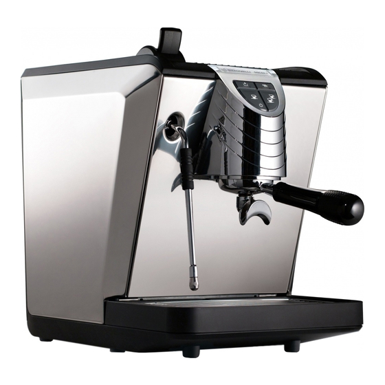
- Page 8 SErvIcE Manual DEScrIPTIOn Fig. 1 lEGEnD Steam lever Cup warming grill Water reservoir Water reservoir hatch Main switch Dispensing unit Water drain tank Cup support grill Filter holder 10 Steam wand 11 Steam wand insulating rubber 12 Control panel AUTORYZOWANY DYSTRYBUTOR w w w .
- Page 9 SErvIcE Manual cOnTrOl PanEl DEScrIPTIOn (configuration standard) Fig. 2 lEGEnD Water level warning light Heating resistance on warning light Two coffee dispensing button / programming entry One coffee dispensing button / Standby AUTORYZOWANY DYSTRYBUTOR w w w . s i m o n e l l i g r o u p . p l Ed.
- Page 10 SErvIcE Manual The manufacturer cannot be held respon- SaFETY InDIcaTIOnS sible for any damages incurred if the sys- The present manual is an integral and essen- tem is not grounded. tial part of the product and is to be delivered For electrical safety, this machine requires to the user.
- Page 11 SErvIcE Manual The appliance is not to be used by children Fig. 5 or persons with reduced physical, sensory or mental capabilities, or lack of experi- ence and knowledge, unless they have been given supervision or instruction. children must not play with the appliance. cleaning and maintenance must not be carried out by children unless supervised.
- Page 12 SErvIcE Manual To prevent dangerous overheating, it is WarnInG advisable to fully extend the power supply DanGEr OF POlluTIOn cord. Fig. 9 never block the intake and/or heat dis- sipation grills, in particular those for the cup warmer. Fig. 7 DanGEr OF InTOXIcaTIOn Once started the washing machine, do not interrupt, the detergent residue may...
- Page 13 Serial InFOrMaTIOn TO THE uSErS Date of number production under the senses of art. 13 of Mod. OSCAR II S.N. SERIALE Date 01/01/0001 QR code QR code 220 - 240 V ~ P= 1200 W law Decree 25th July 2005,...
- Page 14 SErvIcE Manual TranSPOrT The machine is transported on pallets which also contain other machines - all boxed and secured to the pallet with supports. Before carrying out any transport or handling operation, the operator must: • put on work gloves and protective footwear, as well as a set of overalls which must be elasticated at the wrists and ankles.
- Page 15 Service Manual FirST inSTallaTiOn anD PreliMinarY OPeraTiOnS inDeX FirST inSTallaTiOn anD PreliMinarY OPeraTiOnS ..2.1 FirST inSTallaTiOn ... . . 2.2 2.1.1 WeiGHT anD DiMenSiOnS..2.2 2.1.2 cOnnecTiOn TO THe WaTerline anD DrainaGe...
- Page 16 Service Manual FirST inSTallaTiOn riSK OF POlluTiOn 2.1.1 WeiGHT anD DiMenSiOnS DO nOT DiSPOSe PacKaGinG in the environ- NET WEIGHT 14 kg 31 lb ment. Prior to installation please carefully read the GROSS WEIGHT 17 kg 37 lb safety instructions in this manual. The company cannot be held responsible for damage to per- POWER 1200 W...
- Page 17 Service Manual 2.1.2 cOnnecTiOn TO THe WaTerline anD DrainaGe SYSTeM The machine requires stringent specifications to prevent the formation of limescale and to ensure quality beverages. The main features required to achieve high standards of performance are the following: 50 -60 ppm Total hardness Waterline pressure 2-4 bar, cold water...
- Page 18 Service Manual 2.1.3 TecHnical SPeciFicaTiOnS 2.1.5 PrOceDure OF FirST inSTallaTiOn The machine is available in the following ver- sions: Before carrying out the installation carefully read • single-phase 120 V 60 Hz (tank and waterline) the safety instructions at the beginning of this •...
- Page 19 Service Manual acceSSOrieS BOX nOTe Machine is supplied with an accessories box consisting of: In the absence of load water at first boot: Single filter Double filter Could be created air bubble between the Spring pump and reservoir and is preventing the Filter holder passage of water.
- Page 20 Service Manual PrOGraMMinG DOSeS Fig. 18 Carry out the following operations to enter into programming mode: nOTe Operation to be carried out with the machine switched on. To enter into programming mode, press the two coffee dispensing button for 5 seconds. The dispensing buttons start to flash.
- Page 21 SERVICE MANUAL REMOVAL OF THE EXTERNAL SURFACE INDEX TOOLS NEEDED: REMOVAL OF THE EXTERNAL SURFACE ... 3.1 REMOVAL OF WATER TANK ..3.2 REMOVAL OF THE CUp HOLDER SURFACE .
- Page 22 SERVICE MANUAL CUTTING Fig. 22 DANGER Use gloves to protect against sharp or hot surfaces that you can bump against involun- tarily during operations. SURFACES NOTE Before proceeding with the removal of the panels it is advisable to clean and free up enough space where the machine parts will rest so that they are not be unintentionally damaged.
- Page 23 SERVICE MANUAL Pull the water tank upward. Fig. 23 REMOVAL OF THE CUp HOLDER SURFACE To remove the bearing surface of the cup, pro- ceed as follows: Unscrew the screws "A" with a screwdriver. Fig. 24 Lift the panel and pull upwards. Fig.
- Page 24 SERVICE MANUAL REMOVAL OF THE SIDE pANELS Fig. 26 NOTE To remove the side panels, it is necessary to remove the cup holding surface first. Unscrew the "A" present on each panel using a Phillips screwdriver. Fig. 27 Move outside the top of the panel and pull NOTE perform the same steps for the other side panel.
- Page 25 SERVICE MANUAL REMOVAL OF THE FRONT pANEL NOTE To remove the front panel, you must remove the top panels and water from the drain pan. Disconnect the connection to the panel. Fig. 30 Unscrew the screws "A" with a Phillips screwdriver.
- Page 26 SERVICE MANUAL REMOVAL OF KEYBOARD 3.6.1 NOTE Separate the cover unit from the front panel. Fig. 33 Loosen the 4 screws “A” situated on the back of the front panel using a Phillips screwdriver. Fig. 34 Push in the connector located inside of the support group to detach the panel.
- Page 27 SERVICE MANUAL INFUSION UNIT INDEX TOOLS NEEDED: INFUSION UNIT ....4.1 REMOVAL OF SHOWER AND SEAL ....4.2 COFFEE VALVE .
- Page 28 SERVICE MANUAL The underpan seal prevents water from coming Fig. 35 out from the sides of the pavilion and reach the capsule unevenly or spill from the filter holder. Since the material is plastic and exposed to high temperatures, replace the seal periodically, at least once a year or according to machine opera- tion, as it tends to deform, loosening elasticity and sealing.
- Page 29 SERVICE MANUAL COFFEE VALVE Fig. 39 It is a solenoid valve that is normally closed and opens when it received a command to dispense coffee. By closing the decompression removes any excess water from the filter holder. TYPICAL PROBLEMS Check the operation of the valve, if the unit con- tinues to drip continuously or if the coffee cap- sule is too wet.
- Page 30 SERVICE MANUAL Remove the washer and the locking nut “B” Fig. 42 using a 14 mm wrench. Remove the coil. Loosen the coil support “C” with a 24 mm Fig. 43 wrench. Use a 3 mm Allen key to remove the two Fig.
- Page 31 SERVICE MANUAL EXPANSION VALVE To remove the expansion valve, proceed as fol- lows: Fig. 46 Remove the front panel. Disconnect the Teflon tube by removing the cable holder “A” using the pliers. Loosen the valve with a 14 mm wrench. Fig.
- Page 32 SERVICE MANUAL Ed. 02 of 09/2016...
- Page 33 SERVICE MANUAL HEATER INDEX TOOLS NEEDED: HEATER ..... . . 5.1 EMPTYING THE HEATER ..5.2 REMOVAL OF THE HEATER.
- Page 34 SERVICE MANUAL EMPTYING THE HEATER Fig. 49 DANGER Before proceeding with the operations DANGER described in the chapter make sure that the machine is turned off and unplugged from the mains. Discharge any residual pressure pre- sent in the steam heater. WARNING Before carrying out the heater emptying pro- cedure, remove water inlet sources inside the...
- Page 35 Connect the drain pipe and tilt the machine Fig. 53 on the left side to let the water out of the heater. After drainage of water from the heater, Fig. 54 tighten the drain nut “A” using a 13 mm wrench.
- Page 36 SERVICE MANUAL REMOVAL OF THE HEATER In case of need, to remove the heater, it is neces- sary to discharge pressure. Then, proceed as follows: Remove machine covers: • Rear panel; • Side panels; • Front panel. Empty water heater, as in the previous section.
- Page 37 HEATING ELEMENT AND Fig. 57 HEAT PROTECTION To access the heating element, remove the right panel of the cover. The visible parts are: A 167° heat protection. B Electrical connections of heating element. OSCAR II heater features a 1200 W heating ele- ment. To remove the heating element, proceed as fol- lows: Empty the heater as described above.
- Page 38 SERVICE MANUAL REPLACEMENT OF THE Fig. 60 LEVEL GAUGE Water inside the heater is kept at a constant level through the use of a level probe. This probe is connected to the electronic unit, which continuously checks water level. Being always exposed to high temperatures and steam/water it is subject to encrustations which can inhibit operations.
- Page 39 ANTIVACUUM VALVE Fig. 63 The antivacuum valve ensures that air enters the heater during the machine cooling phase. In this way the reduction of water volume due to cooling does not create decompressions that may give rise to drawbacks such as the suction of milk through the steam nozzle.
- Page 40 SERVICE MANUAL SAFETY VALVE Fig. 65 The heater safety valve “A” of heater serves to discharge excess pressure that may form owing to malfunctioning. The valve opens automatically when inner pressure of heater exceeds 2.1 bar. WHEN TO REPLACE For safety reasons each time the valve comes into operation it should be replaced to ensure perfect operation.
- Page 41 SERVICE MANUAL HYDRAULIC CIRCUIT INDEX TOOLS NEEDED: HYDRAULIC CIRCUIT ... 6.1 PUMP DISASSEMBLY ... . . 6.2 REPLACING THE COFFEE VALVE . . . 6.4 STEAM NOzzLE .
- Page 42 SERVICE MANUAL WARNING Before carrying out the disassembly proce- dure of the hydraulic circuit, close water inlet sources inside the waterline: • Waterline version: close the water inlet tap and disconnect the pipe. • Tank version: remove the tank from its seat.
- Page 43 SERVICE MANUAL Disconnect the electrical connections of the Fig. 69 pump using the tweezers: A: temperature probe. B: power supply. Flowmeter Heater Disconnect the hydraulic connections of the Fig. 70 pump: • From the flowmeter, disconnect the Teflon pipe “C”. • From the pump to the heater, unscrew the fitting “D”...
- Page 44 SERVICE MANUAL REPLACING THE COFFEE VALVE Fig. 71 The coffee valve “A” is situated underneath the upper panel, on the left side, and regulates the amount of water flowing inside the heater during all phases of machine operation. WHEN TO INTERVENE The system detects the absence of water and the pump is set off but the pump sounds like it’s straining badly: the valve is stuck.
- Page 45 SERVICE MANUAL Using a 24 mm wrench, remove the fixed Fig. 73 part “C“. Disconnect the hydraulic connections “D” Fig. 74 by using a 12 mm wrench. Loose the locking screws “E” to release the valve from the machine frame. Make sure the plunger is clean and there are Fig.
- Page 46 SERVICE MANUAL STEAM NOzzLE Fig. 76 The steam nozzle is composed of a piston actu- ated by the knob, which presses on a nut with spring return. By pressing against the spring it creates space for the steam to pass. We suggest to replace the seals that keep the piston perfectly aligned, every 4-6 months.
- Page 47 SERVICE MANUAL If there is a loss of steam or condensation, it is Fig. 79 necessary to: Turn the machine off, let out all the steam until there is no pressure in the heater. Remove the left side panel and the front one. Loose the steam nozzle by means of the nut Fig.
- Page 48 SERVICE MANUAL DISASSEMBLY OF THE STEAM LEVER Fig. 82 Remove screw "A" with an Allen key 3 mm. Remove the clip "B" using pliers. Fig. 83 Pull the lever pin "C" to release the steam lever "D". To remove the dispensing nozzle it is suffi- Fig.
- Page 49 SERVICE MANUAL Using a 22 mm wrench remove the steam Fig. 86 nozzle from its housing. We recommend replacing the seal at least once a year. Unscrew the fitting "A" with a 21 mm wrench Fig. 87 to reach the spring. We recommend replacing the seal at least once a year.
- Page 50 SERVICE MANUAL WARNING Operation to be performed when the machine is on. When fixing the screw that holds the lever on the Fig. 90 stream nozzle it is necessary to: Lightly press the lever upwards to let steam come out. Release the lever until the steam supply stops. Tighten the lever locking screw on the steam nozzle.
- Page 51 SERVICE MANUAL WATER TANK To access the water tank, remove the rear panel. NOTE In case of a prolonged inactivity of the machine, the tank valve may be blocked owing to limescale. To release the tank valve, use a screwdriver to allow water discharge.
- Page 52 SERVICE MANUAL 6.4.2 REMOVAL OF THE MAGNETIC Fig. 93 SENSOR This sensor serves to detect the presence of water inside the tank. In case of breakdown or malfunctioning, it can be replaced. Remove the side and rear panels. Move the sensor down, pay attention to the electrical connections.
- Page 53 SERvICE MaNUaL ELECTRIC COMPONENTS INDEX TOOLS NEEDED: ELECTRIC COMPONENTS ..7.1 CONTROL UNIT....7.2 AUTORYZOWANY DYSTRYBUTOR w w w . s i m o n e l l i g r o u p . p l Ed.
- Page 54 SERvICE MaNUaL CONTROL UNIT Fig. 96 To access the main board it is necessary to: Remove the right side panel. Disconnect the electrical connections using the pliers. Loosen the board locking screws “A” on the support using a Phillips screwdriver. The control unit without connections appears as Fig.
- Page 55 SERVICE MANUAL TROUBLESHOOTING INDEX TROUBLESHOOTING... . 8.1 WATER LACK LIGHT....8.2 HEATING ELEMENT LIGHT ..8.3 COFFEE DELIVERY .
- Page 56 SERVICE MANUAL WATER LACK LIGHT Water lack light on. Lack of water in the tank. Fill the tank with drinkable Water in the tank. water. Check the magnetic sen- Float in the tank out of sor. Replace, if necessary. place or faulty. Check float position-...
- Page 57 SERVICE MANUAL HEATING ELEMENT LIGHT Temperature light Heat protection on (oper- operating mode off (after ating temperature consid- 30 min.). erably exceeded). Check the thermal protection and replace it, if necessary. Check the conditions of the pressure switch and when locked in the open state, and replace if nec- essary.
- Page 58 SERVICE MANUAL REMOVAL OF KEYBOARD When pressing the keys, Alarm enabled: nothing happens. • Lack of water; the cor- responding light is on. • Machine not ready; operating temperature not reached; the cor- Check connections and Check the keyboard and, responding light is off.
- Page 59 SERVICE MANUAL HEATER With the water tank full, When reaching the oper- there is no water in the Odour from the heater. ating temperature. heater. Check the coffee valve. Check the anti-vacuum The boiler emits more Replace, if necessary. valve and, if necessary, noise than necessary.
- Page 60 SERVICE MANUAL Ed. 02 of 09/2016...
- Page 61 SERVICE MANUAL DIAGRAMS INDEX DIAGRAMS ....9.1 HYDRAULIC DIAGRAM TANK VERSION ....9.2 HYDRAULIC DIAGRAM DIRECT CONNECTION VERSION .
- Page 62 SERVICE MANUAL HYDRAULIC DIAGRAM TANK VERSION AUTORYZOWANY DYSTRYBUTOR w w w . s i m o n e l l i g r o u p . p l Ed. 02 of 09/2016...
- Page 63 SERVICE MANUAL HYDRAULIC DIAGRAM DIRECT CONNECTION VERSION AUTORYZOWANY DYSTRYBUTOR w w w . s i m o n e l l i g r o u p . p l Ed. 02 of 09/2016...
- Page 64 SERVICE MANUAL WIRING DIAGRAM TANK VERSION AUTORYZOWANY DYSTRYBUTOR w w w . s i m o n e l l i g r o u p . p l Ed. 02 of 09/2016...
- Page 65 SERVICE MANUAL WIRING DIAGRAM DIRECT CONNECTION VERSION AUTORYZOWANY DYSTRYBUTOR w w w . s i m o n e l l i g r o u p . p l Ed. 02 of 09/2016...
- Page 66 SERVICE MANUAL Ed. 02 of 09/2016...
- Page 67 SeRvice ManuaL Maintenance checking inDeX Maintenance checking ..10.1 10.1 DaiLY Maintenance ... 10.2 10.2 WeekLY Maintenance ..10.2 10.3 YeaRLY Maintenance .
- Page 68 SeRvice ManuaL 10.1 DaiLY Maintenance Time required 5 min: Clean the machine; Clean the unit with the blind filter and specific detergent (Pulycaff); Empty the water collection tray. 10.2 WeekLY Maintenance Time required 10 min: Clean the machine; ...
- Page 69 SeRvice ManuaL 10.3 YeaRLY Maintenance Time required 45 - 60 min: The skilled technician should take all the necessary precautions concerning safety measures to insu- late the machine from the mains and to avoid pressure in the heater, waterline closure or tank removal so as to prevent inconveniences or damages.
- Page 70 SeRvice ManuaL 10.4 BienniaL Maintenance Time required 60 - 90 min: The skilled technician should take all the necessary precautions concerning safety measures to insu- late the machine from the mains and to avoid pressure in the heater, waterline closure or tank removal so as to prevent inconveniences or damages.
- Page 71 SeRvice ManuaL annuaL Maintenance 98120001 02280037 98008004 02280020.C 02280011 03000066 02280036 03000073 03000072 01000023 09200014 change every 12 months AUTORYZOWANY DYSTRYBUTOR w w w . s i m o n e l l i g r o u p . p l change every 24 months 10.5 Ed.
- Page 72 SeRvice ManuaL 10.6 Ed. 02 of 09/2016...
- Page 73 E.V. NC 2VOIES 3/4-JG6 DROITE. UL REGUL+FILTR F.2,5 208/240V60Hz 2-WAY SOLENOID VALVE 3/4-JG 6 230V 60HZ UL 04200112 INTERRUPTEUR BIPOLAIRE ROUGE 0/1 RECTANGULAIRE UL 16A 2 POLES SWITCH 16A OSCAR II 05002408 ATION PUMP V230/50 03002460 ATION PUMP 115V 60Hz...
- Page 74 SERVICE MANUAL 11.1 CABINET PARTS 05000758 00000174 00000231 00000089 05002404 00000011 00000175 00000175 03002462 05002406 00000011 03002454 01000268 00000204 00000204 00000232 03002450 01000268 01000268 31000700 00000050 04901090 03002452 05002400.C 00000175 05000185 05002408 03002460 05000185 05002412 00000009 05002410 SPECIFICARE COLORE (SPECIFY COLOR) AUTORYZOWANY DYSTRYBUTOR w w w .
- Page 75 SERVICE MANUAL 11.2 COMPLETE POURING UNIT 00300040 11600002 00300040 08000003 98120001 00000118 COMPLETE GROUP 02290016 980400000001000001 230V 980400000001000002 115V 04100038 230V 04100037 115V 73004013 00000118 08000003 02280020.C 11600002 07300183 00000221 03000066 00000217 03000073 03000107 03000072 05000843-C 08000017 05000082 05000844-G 07300601 98005050 05000840-G 06200086...
- Page 76 SERVICE MANUAL 11.3 TANK - FRAME COMPONENTS AUTORYZOWANY DYSTRYBUTOR w w w . s i m o n e l l i g r o u p . p l 03002458 05000187 05000186 00000089 00000199 00000011 05000186 00000199 05000187 05180006 00000011 05002230 04100060 230V 50Hz...
- Page 77 SERVICE MANUAL 11.4 STOVE FILED COLLECT WATER 00000231 98200000000020 00000231 05002414 05000759 04000685 00000155 02280018 05002416 00000155 08000015 07300355 00000118 07300810 04100005 230V 07300720 04100006 115V 02280014 07300221 07300138 02280014 07300354 07300218 08000027 02280037 07300293 98110001 02280004 98008004 07300450 07300295 98060030 08000005 07300364...
- Page 78 SERVICE MANUAL 11.5 BOILER COMPONENTS 01000267 09200014 01000265 09200006 98030444 01000023 03000202 09500014 (167°C) 07300365 98013021 01000266 09000006 07300227 05000063 07300459 02280009 00300002 14100040 230V 14100041 115V 07300382 07300362 98030440 00300002 00300026 07300091 00300002 07300365 98030446 AUTORYZOWANY DYSTRYBUTOR 98030442 98030448 w w w .
- Page 79 SERVICE MANUAL 11.6 ELECTRICAL COMPONENTS 05000270 04901094 230V 04000690 04901095 115V 00000047 00000047 04000660 04200112 04080043 04060002 AUTORYZOWANY DYSTRYBUTOR w w w . s i m o n e l l i g r o u p . p l 11.7 Ed.
- Page 80 E.V. NC 2VOIES 3/4-JG6 DROITE. UL REGUL+FILTR F.2,5 208/240V60Hz 2-WAY SOLENOID VALVE 3/4-JG 6 230V 60HZ UL 04200112 INTERRUPTEUR BIPOLAIRE ROUGE 0/1 RECTANGULAIRE UL 16A 2 POLES SWITCH 16A OSCAR II ATION PUMP V230/50 ATION PUMP 115V 60Hz TROMECHANICAL PUMP 220V 60Hz 64W...
- Page 81 TUYAU VAPEUR - CHAUDIERE OSCAR II PIPE BOILER-STEAM VALVE OSCAR II ILER-PRESSURE SWITCH OSCAR II 98030446 TUYAU SUPERIEUR GROUPE DIST.- CHAUDIERE OSCAR II TOP PIPE HEAT EXCHANGER-GROUP OSCAR II 98030448 TUYAU INFERIEUR GROUPE DIST.- CHAUDIERE OSCAR II BOTTOM PIPE HEAT EXCHANGER-GROUP OSCAR II...
- Page 82 SERVICE MANUAL 11.10 Ed. 01 of 12/2015...
- Page 84 Fax +39.0733-950242 www.nuovasimonelli.it E-mail: n.simonelli@nuovasimonelli.it Nuova Distribution Centre LLC 6940Salashan PKWY BLDG A 98248 Ferdale, WA Ph. +1.360.3662226 Fax +1.3603664015 videoconf. +1.360.3188595 www.nuovasimonelli.it info@nuovasimonelli.com Nuova Simonelli reserves the right of make all modifications deemed to be necessary. Graphic: TYPE ENGINEERING S.r.l...
Need help?
Do you have a question about the OSCAR II and is the answer not in the manual?
Questions and answers