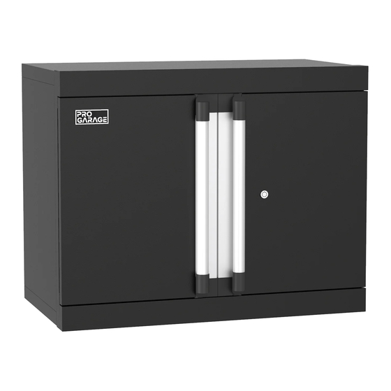
Summary of Contents for ClosetMaid PRO GARAGE 10844
- Page 1 10844 Wall Cabinet INSTALLATION INSTRUCTIONS 01-18644-00 06/20 © 2020 ClosetMaid LLC | Ocala, FL 34471 | 1-800-874-0008 | www.closetmaid.com...
-
Page 2: Before Beginning
SAFETY PRECAUTIONS BEFORE BEGINNING • Please read all instructions carefully. • Familiarize yourself with all parts (see “PARTS”) and check quantities. • Follow all safety precautions (see “SAFETY PRECAUTIONS”). WARNING • • CHOKING HAZARD FOR SMALL CHILDREN. This unit DO NOT CLIMB OR STEP ON THE UNIT. The unit may contains small parts which could be a choking hazard for become unstable and either tip or collapse. -
Page 3: Tools Required
PARTS Call 1-800-874-0008 for parts and service. For faster service, have the style number ready when calling. TOOLS REQUIRED 5/16 in. Masonry 7/16 in. and 1/2 in. #2 and #3 Phillips Level Drill Hammer Drill Bit Screwdrivers Wrenches HARDWARE PROVIDED Name Qty. - Page 4 PARTS Call 1-800-874-0008 for parts and service. For faster service, have the style number ready when calling. PRODUCT Name Part # Name Part # Left Side Panel 35872 Exterior Cabinet Bracket 20614 Right Side Panel 35873 Interior Cabinet Bracket 20614 Back Panel 35874 Cabinet Spacer...
- Page 5 STEP 1 Attach side panels to back panel. Align both side panels (A & B) with the back panel (C) as shown. Slide the metal tabs on the back panel (C) into the matching slots on the side panels (A & B). Pull the side panels down to secure the tabs in place.
- Page 6 STEP 2 Attach bottom panel. Align bottom panel (D) with the bottom of the unit as shown. Push in to secure into place. Make sure that all the triangular tabs on the back and side panels completely snap into place in the square holes on the bottom panel. *Please note location of predrilled holes on each part.
- Page 7 STEP 3 Attach shelves. Place the bottom shelf (F) inside the unit at the bottom. Push down to secure into place, making sure all metal tabs are connected. Please note that the bottom shelf is larger than the inner shelf and will rest on the lowest three metal tabs on the back panel.
- Page 8 STEP 4 Attach brackets, spacers, and electrical bushing. Align the exterior brackets (H) and interior brackets (I) with the upper square holes on the back panel. Use a 1/2 in. wrench to secure the brackets through the holes using two 5/16-18 x 3/4 in. carriage bolts (AA), two 5/16-18 x 3/4 in. flange nuts (BB), and two 5/16 in.
- Page 9 STEP 5 Attach top panel. Align top panel (E) with the top of the unit as shown. Push in to secure into place. Make sure that all the triangular tabs on the back and side panels completely snap into place in the square holes on the top panel. *Please note location of predrilled holes on each part.
- Page 10 STEP 6 Secure top and bottom panels. Use a #2 Phillips screwdriver to secure the top and bottom panels to the unit using eight ST5 x 12 mm. bolts (GG) on the front corners of the unit and two bolts on the back corners. #2 Phillips x 10 *Please note location of predrilled holes on each part.
- Page 11 STEP 7 Attach doors. Align the right door (L) with the right side of the unit. Place the bottom lock of the door in the hole on the bottom of the door frame. Pull the top lock down, align it with the hole on the top of the door frame, and push up to lock into place.
- Page 12 STEP 8a Attach to wall via concrete mounting. Identify which installation works best for your space. Align the unit with the location on the wall where you plan to mount it. Ensure unit is level and use a pencil to mark the top two corners of the unit on the wall and set the unit aside.
- Page 13 STEP 8b Attach to wall via stud mounting. Locate studs and align the unit with the location on the wall where you plan to mount it. Ensure unit is level, use a pencil to mark the top two corners of the unit on the wall, and set the unit aside. Measure 2-11/16 in. down from the corner marks and make two new marks.


Need help?
Do you have a question about the PRO GARAGE 10844 and is the answer not in the manual?
Questions and answers