Table of Contents
Advertisement
Advertisement
Table of Contents

Related Manuals for Price Antec Controls VENTURI VV Series


Summary of Contents for Price Antec Controls VENTURI VV Series
- Page 1 VENTURI VALVE VV Series MANUAL v113...
-
Page 2: Table Of Contents
TABLE OF CONTENTS INTRODUCTION ....................................1 General ......................................1 Safety Precautions..................................1 Caution to Contractors.................................1 Product Overview ..................................2 Technical Specifications ................................2 Airflow Ranges ....................................2 GETTING STARTED WITH THE VV ..............................3 Receiving Inspection ...................................3 In the Box ....................................3 Construction Options...................................5 INSTALLATION & MOUNTING INSTRUCTIONS ..........................10 Installing the Venturi Valve ................................10 Constant Volume Valve Reassembly ............................12 VALVE ACCESSORIES ...................................13... -
Page 3: Introduction
INTRODUCTION General In this manual, you will find information regarding: • Venturi Valve (VV) specifications This mark indicates an important point for the proper • How to install the VV with Constant Volume, Variable function of the Venturi Valve. Improper setup may Volume, and Two Position (2P) Switch cause unit failure. -
Page 4: Product Overview
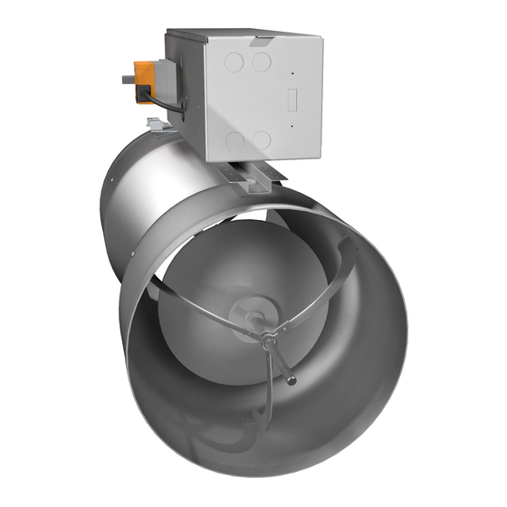
Product Overview Venturi Valves are mechanically pressure independent airflow control valves designed specifically for room pressure and fume hood control applications. Some of the key features include: • Electronic airflow feedback prevents dust/lint contamination from deteriorating airflow reading • Characterized using NVLAP-accredited airflow stations •... -
Page 5: Getting Started With The Vv
GETTING STARTED WITH THE VV Receiving Inspection After unpacking the assembly, check carefully for shipping damage. If any damage is found, report it immediately to the delivering carrier. During unpacking and installation, do not handle the valve by the inlet cone shaft or center shaft support bracket. - Page 6 Two Position (2P) Venturi Valve 2P valves will ship with the following components. Component Quantity Description Valve Body 1, 2 or 3 Venturi Valve NOTE: Dual and Triple VAV valves will be shipped as a ganged assembly. Green Pressure The low-pressure tubing comes factory installed Tubing connected to the valve’s control system and a connector tee for field verification.
-
Page 7: Construction Options
Construction Options Below is an outline of some of the key options that are available when selecting and ordering Venturi Valves. These options will affect its available flow range, how the valve is installed and under what system conditions it must operate. See the VV Product Submittal on AntecControls.com for specifications and dimensions of each option shown below. - Page 8 Pressure Range Venturi Valves can be ordered for either Medium or Low Pressure operation. CAUTION This selection will affect the operating airflow range of the valve. Ensure that the Venturi Valve is in the specified Pressure Range before balancing the valve. Medium Pressure Model: VV-M...
- Page 9 Valve Orientation Venturi Valves are available in Vertical Up, Vertical Down, and Horizontal CAUTION orientations. An airflow direction label is on the valve and indicates the direction of airflow and the valve’s orientation. Do not install valves in an orientation other than what is indicated on the valve.
- Page 10 Control Type The control type specifies whether the valve is provided with controls and an actuator or is a mechanically fixed assembly. Constant Volume Model: VV-CV Features: • Mechanical linkage to lock the valve in place • If airflow adjustments are required, they are done manually •...
- Page 11 Aluminum Model: VV-AL Features: Aluminum valve body with Stainless Steel (SS) internal hardware Can be mounted using sheet metal screws. NOTE: Phenolic – Class 1 Model: VV-P1 Features: Phenolic coated valve body with Stainless Steel (SS) internal hardware Scratches and holes can compromise the coating NOTE: Do not use sheet metal screws to install.
-
Page 12: Installation & Mounting Instructions
INSTALLATION & MOUNTING INSTRUCTIONS Installing the Venturi Valve The instructions below detail general installation of a Venturi Valve without the use of any valve accessories. When using accessories with the Venturi Valve, please see the appropriate installation detailed for the accessory being used in the Valve Accessories section. - Page 13 Slip-Connection Venturi Valve Mounting Instructions The instructions below are detailed for Aluminum Venturi Valves only. Do not use screws for Phenolic or Kynar coated valves. STEP 1 Mount the Venturi Valve by slipping both the inlet and the discharge one inch (1”) into the appropriately sized ductwork.
-
Page 14: Constant Volume Valve Reassembly
Constant Volume Valve Reassembly After installing a Constant Volume (CV) Venturi Valve and before turning air on to the system, it is necessary to reconnect the factory calibrated linkage. STEP 1 Cut cable tie and remove instruction tag from the valve. For a multi-body valve there will be more than one cable tie. -
Page 15: Valve Accessories
VALVE ACCESSORIES Venturi Valves can function with a variety of different products to control air temperature, decrease noise, and improve ease of installation. Valve accessories and optional products provided by CAUTION Antec Controls include: 1. Hot Water Coils (VVHWC) 2. Electric Coils (VVEC) Different types of valve accessories can be used with the 3. - Page 16 Installation STEP 1 Hot water coils are only available in supply orientation and should always be located down stream of the supply Venturi Valve. STEP 2 For single VVHWC’s, position the bead connection so that it faces the airflow. For multibody VVHWC’s, position the slip connection so that it faces the airflow. NOTE: Both single and multibody valves have slip and drive connections that will face down stream of the airflow.
-
Page 17: Electric Coils (Vvec)
Electric Coils (VVEC) Electric Coils (VVEC) are devices installed with Venturi Valves that control room environment by heating the air moving through the valve. The VVEC operates using standard building electrical power and is designed to optimize heat transfer. Overview See the VVEC Product Submittal on AntecControls.com for specifications and dimensions of the options below. - Page 18 Electrical Installation 1. Review Electrical Wiring diagram included with heater (typically glued to inside of electrical enclosure door). 2. Ensure circuit powering the heater has proper capacity. Follow local building codes. 3. The electric duct heater must have an uninterrupted or unbroken electrical ground to minimize the chance of injury should an electrical fault occur.
-
Page 19: Silencer (Vvsil)
Silencer (VVSIL) Silencer (VVSIL) is a highly engineered 14 inches silencer specifically designed for the full spectrum attenuation of sounds produced by Venturi Valves. The packless design provides minimal disturbance in the airflow resulting in low pressure drops across the silencer. Overview See the VVSIL Product Submittal on AntecControls.com for specifications and dimensions. -
Page 20: Valve Companion Connections (Vct)
Valve Companion Connections (VCT) Valve Companion Connections (VCT) come in two different types: drawband clamps and companion flanges. Drawband clamps are designed as a connection method specifically for slip Venturi Valves. Drawband clamps are an alternative to directly fastening the valve to the ductwork. The drawband clamp provides uniform compression, connecting spiral or plain ductwork to a valve, ensuring that the valve is properly supported. - Page 21 Slip-Connection Venturi Valve with Drawband Clamps Installation STEP 1 Slide drawband clamps completely onto the inlet and discharge ductwork. STEP 2 Mount the Venturi Valve by slipping both the inlet and the discharge one inch (1”) into the appropriate sized ductwork. STEP 3 Apply appropriate tape to seal valve to duct work if required.
- Page 22 Flange-Connection Venturi Valve with Companion Flanges Installation STEP 1 Slide companion flanges completely onto the inlet and discharge ductwork with the flanged end of the companion flanges toward the free space. STEP 2 Align hole pattern to match opposing companion flange as shown. STEP 3a For Aluminum Companion Flanges, fasten each companion flange with six (6 ) sheet metal screws.
-
Page 23: Valve Installation Tape (Vit)
Valve Installation Tape (VIT) Valve Installation Tape (VIT) is used during installation of the Venturi Valve in corrosive applications and is wrapped around the valve and ductwork connection to ensure an airtight seal. Overview See the VIT Product Submittal on AntecControls.com for specifications. Options Valve Installation Tape Model:... -
Page 24: Valve Pressure Switch (Vps)
Valve Pressure Switch (VPS) Valve Pressure Switch (VPS) is an adjustable, pressure-actuated electrical switch that makes or breaks an electrical circuit at a predetermined pressure. Overview See the VPS Product Submittal on AntecControls.com for specifications and dimensions. Options Valve Pressure Switch (VPS) Model: Features: •... - Page 25 Field Adjustment STEP 1 Ensure that the VPS is being calibrated at a temperature as close to the actual operating temperature as possible. STEP 2 The set point range adjusting screw is located on the underside of the switch. To get access to the adjusting screw, unmount the VPS from the valve by removing the screws on both mounting feet.
-
Page 26: Valve Actuator
Valve Actuator Valve actuators are wired into the valve controller and are attached to the linkage bars of the valve. The actuator controls the position of the cone assembly inside of the Venturi Valve which controls the amount of air that flows through the valve. Valve actuators come in two main options: Standard Speed and High Speed. -
Page 27: Valve Relay
Valve Relay Valve relays are miniature switches that use electromagnetic coils to close or open a circuit. Overview See the Valve Relay Product Submittal on AntecControls.com for specifications and dimensions. Options Valve Relay Model: Valve Relay • Latching levers for convenient circuit checking Features: •... -
Page 28: Balancing
BALANCING The balancing process is required in the field to ensure that the valves are providing the necessary flow into and out of the pressure-controlled space. The process involves measuring the airflow through the valve in the field, using third party calibrated equipment and comparing it to the calibrated position feedback from the Venturi Valve. -
Page 29: Constant Volume Venturi Valve
Constant Volume Venturi Valve Constant Volume Valves are factory calibrated for a selected airflow and can be installed in the field without adjustment for maintenance free operation. The valve can be adjusted in the field if changes to the airflow are required. The control arm is held in place with two locking nuts. -
Page 30: Troubleshooting
TROUBLESHOOTING Venturi Valve Troubleshooting Symptoms Possible Cause Foreign material in valve Noise Vibrating duct work Confirm that power is being delivered to the unit Verify control signal Actuator does not operate Verify that the disconnect switch (where available) is not open for Variable Volume Valves Verify that the fuse (where available) is not blown Verify there are no ductwork obstructions... -
Page 31: Replacement Parts
Replacement Parts Replacement parts are available. Please contact your local Antec Controls Representative. Technical Support If technical support is required, please contact us: By Email @ FieldSupport@AntecControls.com By Phone @ 866-884-3524 Hours of Operation: Monday – Friday, 8am to 4:30pm CST NOTE: If you will need support after hours, please contact us 48 hours in advance. - Page 32 Limited Warranty. The complete product catalog can be viewed online at AntecControls.com ® Antec Controls by Price is a registered trademark of Price Industries Limited. © 2021. Printed in Canada. v113...
Need help?
Do you have a question about the Antec Controls VENTURI VV Series and is the answer not in the manual?
Questions and answers