Table of Contents
Advertisement
Quick Links
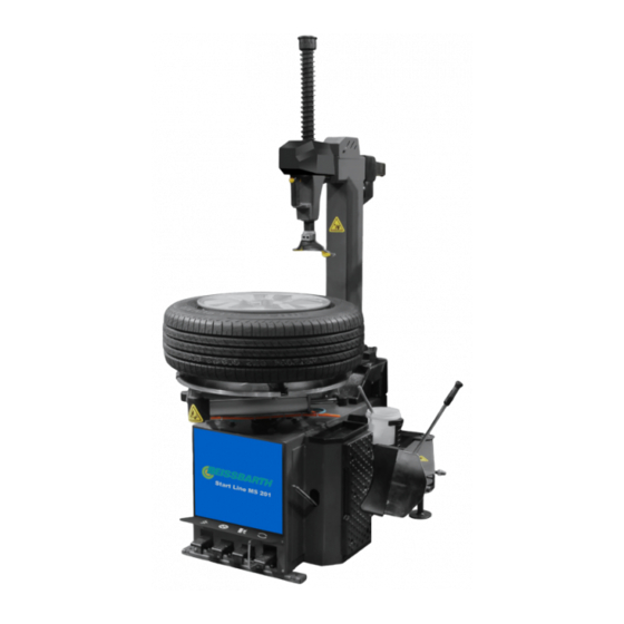
Start Line MS 201
de Originalbetriebsanleitung
Reifenmontiermaschine
es Manual original
Máquina para montaje de neumáticos
en Original instructions
Tire changer
it Istruzioni originali
Smontagomme
Reifenmontiergeräte
Tyre Changers
fr Notice originale
Machine à monter les pneus
pt Manual original
Máquina de montagem de pneus
Advertisement
Table of Contents

Related Manuals for Beissbarth Start Line MS 201


Summary of Contents for Beissbarth Start Line MS 201
- Page 1 Reifenmontiergeräte Tyre Changers Start Line MS 201 de Originalbetriebsanleitung en Original instructions fr Notice originale Reifenmontiermaschine Tire changer Machine à monter les pneus es Manual original it Istruzioni originali pt Manual original Máquina para montaje de neumáticos Smontagomme Máquina de montagem de pneus...
-
Page 3: Table Of Contents
| Start Line MS 201 | 27 Content English Symbols used Mounting the tire In the documentation 7.8.1 Selecting the tire 1.1.1 Warning notices - 7.8.2 Preparing the tire Structure and meaning 7.8.3 Positioning of the mounting head 1.1.2 Symbols in this documentation 7.8.4... -
Page 4: Symbols Used
28 | Start Line MS 201 | Symbols used Symbols used On the product In the documentation Observe all warning notices on products and ensure 1.1.1 Warning notices - they remain legible. Structure and meaning Warning notices warn of dangers to the user or Danger –... -
Page 5: User Instructions
User instructions | Start Line MS 201 | 29 User instructions The MS 201 has been designed for use by personnel with basic mechanical and electrical General provision skills. For this reason, the description of basic ¶ This operating manual is an essential part of the operations such as how to tighten screws may product. -
Page 6: Safety Requirements And Notes
30 | Start Line MS 201 | Symbols used Safety requirements and notes ¶ The operator must pay attention to the following: ¶ The MS 201 must only be operated by authorized All requirements in the operating manual must be personnel who have received special training. -
Page 7: Product Description
Product description | Start Line MS 201 | 31 Product description The MS 201 must be installed correctly, operated correctly and also serviced periodically. Intended use MS 201 is used to demount/ mount the car tire. The dimension of the rim is 9”-22”. The maximum wheel diameter is 1050 mm, the maximum tire width 13". -
Page 8: Transport
32 | Start Line MS 201 | Product description Unpacking Scope of delivery Denomination Quantity Unpacking ¶ MS 201 When unpacking, the operator should wear the Bead beaker assembly proper protective gear such as protective gloves. Mounting lever ¶ Check the delivery carefully to make sure that all Inflation gun with pressure gauge parts have been delivered. - Page 9 Unpacking | Start Line MS 201 | 33 3. Lift the mounting arm onto the MS 201 as shown 6. Connect the fixed axis insert to the bead breaker in the figure below. cylinder and mounting column, and then fasten.
-
Page 10: Initial Commissioning
34 | Start Line MS 201 | Unpacking Initial commissioning 9. To connect the air hose, open the side panel of machine housing, then attach the air hose to the Initial commissioning straight connector. Installation environment requirement: Initial commissioning Requirement Temperature 4 - 40 ºC... -
Page 11: Fastening The Ms 201
Initial commissioning | Start Line MS 201 | 35 Fastening the MS 201 If the MS 201 will not be used for a long time and the machine is connected directly to the For the procedure when lifting the MS 201, electrical cabinet instead of via a plug, the electrical please see the figure. -
Page 12: Operation
36 | Start Line MS 201 | Initial commissioning Operation ¶ Depress the clamping jaws control pedal 7-2 to the second position and the clamping jaws immediately stop. The following information must be read, and will be ¶ Depress the clamping jaws control pedal 7-2 to the helpful to the operator to simplify the steps needed third position and the clamping jaws close. -
Page 13: Unseating The Tire Bead
Operation | Start Line MS 201 | 37 Unseating the tire bead Pay special attention when demounting/mounting tire that the rim or tire are not damaged. Not using the grease will seriously damage the tire. In the process of inflating the tire, there is a risk that Please use the special grease. -
Page 14: Rim Location Direction
38 | Start Line MS 201 | Operation Rim location direction 4. Depress the blade control pedal 7-3 to make the blade start working. How to decide from which side of the wheel to 5. When the bead is broken, release the pedal at once. -
Page 15: Clamping The Rim
Operation | Start Line MS 201 | 39 Clamping the rim Demounting the tire When the mounting arm swings out, no one is Warning: Risk of damage to the tire and rim! allowed in the range of its movement. Excessive contact pressure may cause internal or external tearing in the tire. -
Page 16: Positioning Of The Mounting Head
40 | Start Line MS 201 | Operation 7.7.1 Positioning of the mounting head 7.7.2 Lever the top bead over the rim flange 1. Hold the bead-lifting lever firmly while keeping Warning – Risk of hand injuries! space for the mounting head. -
Page 17: Demounting The Top Bead
Operation | Start Line MS 201 | 41 Mounting the tire 7.7.3 Demounting the top bead 1. Depress the pedal 7-4 and rotate the wheel until the top bead is completely detached from the rim. Risk of accident from damaged rims and 2. -
Page 18: Selecting The Tire
42 | Start Line MS 201 | Operation 7.8.1 Selecting the tire 7.8.4 Mounting the lower tire bead 1. Simultaneously place the bottom bead under the Before selecting the tire, you should know all nose of the mounting head and on the end of the of its technical features, technical parameters, mounting head. -
Page 19: Procedure For Mounting/Demounting Alloy Rims
Operation | Start Line MS 201 | 43 Inflation Procedure for mounting/demounting alloy rims Inflation can lead to hazardous situations. On some alloy rims, the rim channel at the middle The user must undertake the necessary of the rim is very shallow or there is no rim channel. -
Page 20: Inflating Tubeless Tires
44 | Start Line MS 201 | Inflation Inflating tubeless tires Inflating tubed tires 1. Ensure that the rim is held securely on the turntable 1. Ensure that the rim is held securely on the turntable and that the mounting head and tire pressing disk and that the mounting head and tire pressing disk are not in contact with the tire. -
Page 21: Maintenance
Maintenance | Start Line MS 201 | 45 Maintenance Maintenance operations 9.2.1 Maintenance unit and bead breaking cylinder Warning Perform \the following operation at least once every Non-professional personnel should not perform 30 days. maintenance. 1. Check the oil level in the oil cup. If there is not... -
Page 22: Belt
46 | Start Line MS 201 | Maintenance 9.2.2 Belt If the lifting device moves too slow and the column tilts too slow, you should operate as per the Periodically adjust the tension of the motor belt as following steps shown in figure below. Clean the per the following steps: silencer. -
Page 23: 10. Troubleshooting
Troubleshooting | Start Line MS 201 | 47 10. Troubleshooting Faults affecting operation of the machine may occur in the course of normal working MS 201. The following table lists possible faults not requiring expert attention. To take action as quickly as possible it is important to quote the details on the rating plate (label on back of MS 201) and the nature of the problem when calling. -
Page 24: 11. Decommissioning
48 | Start Line MS 201 | Decommissioning 11. Decommissioning 11.3.2 MS 201 and accessories 1. Disconnect the MS 201 from the mains and 11.1 Change of location detach the power cord. 1. Disconnect the electrical connection. 2. Dismantle the MS 201 and sort out and dispose 2. -
Page 25: 12. Technical Parameter
Technical Parameter | Start Line MS 201 | 49 12. Technical Parameter 12.4 Bead breaker blade 12.1 Dimensions for Function Decompression system Fix style Manual Function Dimensions Enter style Manual Max. working size 340 mm Length A=1120 mm Bead breaker blade pressure 2500 kg...
Need help?
Do you have a question about the Start Line MS 201 and is the answer not in the manual?
Questions and answers