Table of Contents
Advertisement
Available languages
Available languages
Quick Links
Mod.
1067
DS1067-107A
LBT20709
IOTC INTERFACES
INTERFACE IOTC
IOTC-SCHNITTSTELLEN
Ref. 1067/011
Through the following QR Code, it is possible to download the new version of the booklet.
Par le QR Code suivant, il est possible de télécharger la nouvelle version du notice.
Über den folgenden QR-Code kann die neue Version der Broschüre heruntergeladen werden.
http://qrcode.urmet.com/default.aspx?prodUrmet=136129&lingua=en
Advertisement
Table of Contents

Subscribe to Our Youtube Channel
Related Manuals for urmet domus IOTC 1067


Summary of Contents for urmet domus IOTC 1067
- Page 1 Mod. 1067 DS1067-107A LBT20709 IOTC INTERFACES INTERFACE IOTC IOTC-SCHNITTSTELLEN Ref. 1067/011 Through the following QR Code, it is possible to download the new version of the booklet. Par le QR Code suivant, il est possible de télécharger la nouvelle version du notice. Über den folgenden QR-Code kann die neue Version der Broschüre heruntergeladen werden.
-
Page 2: General Description
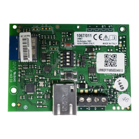
GENERAL DESCRIPTION The IOTC 1067/011 interface is an optional device, which can be used to remotely manage the control units Ref. 1067/024 and Ref. 1067/032A using a mobile device and/or tablet via a modem router. - Page 3 INSTALLATION IN BOX 1067/018 DS1067-107A...
- Page 4 Box bottom of the 1067/024 – 1067/032A control unit Fig. 8 Location Device Expansion 1067/008A or 1067/011 Expansion 1067/008A or 1067/010 or 1067/020 or 1067/011 The module can be installed in three different ways: Inside the 1067/xxx control unit in a special location (see Fig. 8 and location table). ...
-
Page 5: Bus Connection
BUS CONNECTION CAUTION Always connect and disconnect the devices to the bus with the control panel not powered (mains and battery disconnected). Refer to the installation manual of control unit 1067 with regard to the cable section, distances and extensions. ... - Page 6 During normal operation, by pressing the programming button, the board runs a short LED sequence, which specifies the address acquired. Reset and Programming button The IP interface board Ref.1067/014 being acquired, is recognised by the system 1067 as a keypad and the first available address is assigned to it.
-
Page 7: Reset Of The Device
RESET OF THE DEVICE Proceed as follows to reset the device: From any keypad in the system, enter the Installer code in the "Maintenance" menu and delete the device from the "Delete/Keypads" menu (the device was previously acquired as a keypad, delete the one with the correct address. -
Page 8: Technical Specifications
TECHNICAL SPECIFICATIONS ⎓ Nominal power voltage ........................9 ÷ 15V ⎓ Rated Current ......................70mA ±30% @ 13,8 V LAN baud rate ..........................10Mbps WiFi baud rate ..........................54Mbps Operating temperature......................-10°C ÷ +40°C Average relative humidity during operation ..................25 ÷ 75% Dimensions (w x h x d) ...................... -
Page 9: Description Générale
Urmet Secure, téléchargeable à l’adresse www.urmet.com. DESCRIPTION GÉNÉRALE L’interface IOTC 1067/011 est un dispositif optionnel qui permet de gérer à distance via des dispositifs mobiles et/ou des tablettes, les centrales Réf. 1067/024 et Réf. 1067/032A par un modem routeur. - Page 10 INSTALLATION DANS LE BOITIER 1067/018 Fond de la boîte des les centrales 1067/024 – 1067/032A DS1067-107A...
- Page 11 Fig. 8 Logement Dispositif Extension 1067/008A ou 1067/011 Extension 1067/008A ou 1067/010 ou 1067/020 ou 1067/011 Le module peut être installé de trois manières différentes : À l'intérieur de la centrale dans un logement spécial (voir Fig. 8 et tableau des logements). ...
- Page 12 CONNEXION DE BUS ATTENTION La connexion et la déconnexion des dispositifs au bus doivent être effectuées lorsque la centrale est hors tension (réseau et batterie débranchées). Pour la section des câbles, les distances et les rallonges, se reporter à la notice d’installation de la centrale 1067.
- Page 13 En fonctionnement normal, en appuyant sur le bouton de programmation, la carte exécute une courte séquence-LED qui spécifie l’adresse acquise. Bouton de RAZ et de programmation La carte d’interface IP Réf. 1067/014, en cours d’acquisition, est reconnue par le système 1067 en tant que clavier et on lui attribue la première adresse disponible.
- Page 14 RAZ DU DISPOSITIF Si on souhaite réinitialiser le dispositif, il faut : À partir de n'importe quel clavier du système, entrez le code Technicien dans le menu "Maintenance" et supprimez le dispositif du menu "Suppression/Claviers" (le dispositif était précédemment acquis en tant que clavier, supprimez celui portant l'adresse correcte.
-
Page 15: Caracteristiques Techniques
CARACTERISTIQUES TECHNIQUES ⎓ Tension nominale d’alimentation....................9 ÷ 15V ⎓ Absorption nominale ....................70mA ±30% @ 13,8 V Débit en bauds connexion LAN ......................10Mbps Débit en bauds connexion WiFi ......................54Mbps Température de fonctionnement ................... -10°C ÷ +40°C Humidité relative moyenne de fonctionnement ................25 ÷ 75% Dimensions (l x h x p) ...................... -
Page 16: Allgemeine Beschreibung
ALLGEMEINE BESCHREIBUNG Die IOTC 1067/011-Schnittstelle ist ein optionales Gerät, mit dem die Steuergeräte ferngesteuert werden können. 1067/024 und Ref. 1067 / 032A mit einem mobilen Gerät und / oder Tablet über einen Modemrouter. Das Gerät kann auf zwei Arten mit dem LAN-Netzwerk verbunden werden: ... - Page 17 INSTALLATION IN BOX 1067/018 Gehäusebo den der Zentrale 1067/024 - 1067 / 032 DS1067-107A...
- Page 18 Abb. 8 Standort Gerät Erweiterung 1067/008A oder 1067/011 Erweiterung 1067/008A or 1067/010 or 1067/020 or 1067/011 Das Modul kann auf drei verschiedene Arten installiert werden: • In der Zentrale 1067/xxx an einem bestimmten Ort (siehe Abb. 8 und Standortstabelle). • Wandmontage mit Schrauben und Bolzen (siehe Abb. 4). In diesem Fall, Verwenden Sie Box Ref. 1067/018.
- Page 19 KONFIGURATION Nachdem Sie das Gerät positioniert und mit dem Bus der Zentral verbunden haben (Vorgang, bei dem die Zentrale mit Strom unversorgt ist), fahren Sie wie folgt fort: Geräteerfassung am Bus Gehen Sie wie folgt vor, um das Erfassungsverfahren durchzuführen: 1.
- Page 20 LED VORGANG Flash/Beschreibung Nach einem Hardware-Reset blinkt die LED auf der Platine wie bei den Tastaturen 10 Sekunden lang. Rücksetzung der Platine im Access Point-Modus, nicht von der Zentrale erfasst: 1 blinkt ungefähr alle 2 Sekunden. Rücksetzung der Platine im Access Point-Modus, ist von der Zentrale erfasst worden: 2 langsame Blinkzeichen mit einem Intervall von 8 Sekunden zwischen den Sequenzen.
- Page 21 TECHNISCHE SPEZIFIKATIONEN Nennspannung……………………………………………………………………………………………….9 ÷ 15V⎓ Nennstrom ………………………………………………………………………………..70 mA ± 30% bei 13,8 V⎓ LAN-Baudrate…………………………………………………………………………………………………10 Mbit/s WiFi-Baudrate…………………………………………………………………………………………………54 Mbit/s Betriebstemperatur………………………………………………………………………………….-10° C ÷ + 40° C. Durchschnittliche relative Luftfeuchtigkeit während des Betriebs………………………………………25 ÷ 75% Abmessungen (B x H x T)…………………………………………………………………………108 x 91 x 31 mm SYMBOLSCHLÜSSEL Symbol Beschreibung...
- Page 22 ENGLISH SIMPLIFIED EU DECLARATION OF CONFORMITY Hereby, Urmet S.p.A. declares that the radio equipment type: IOTC Interfaces – Ref. 1067/011 is in compliance with Directive 2014/53/UE. The full text of the EU declaration of conformity is available at the following internet address: www.urmet.com FRANÇAIS DECLARATION UE DE CONFORMITE SIMPLIFIEE...
Need help?
Do you have a question about the IOTC 1067 and is the answer not in the manual?
Questions and answers