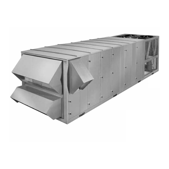
York eco2 050 Installation Operation & Maintenance
Packaged rooftop air conditioning units
Hide thumbs
Also See for eco2 050:
- User manual (76 pages) ,
- Installation & operation manual (168 pages)

Subscribe to Our Youtube Channel
Related Manuals for York eco2 050


Summary of Contents for York eco2 050
- Page 1 PACKAGED ROOFTOP AIR CONDITIONING UNITS INSTALLATION, OPERATION & MAIN TE NANCE Supersedes: Form 100.50-NOM1 (502) Form 100.50-NOM1 (604) 50 THROUGH 105 TONS R-407C AND R-22 DESIGN LEVEL C 00566VIP...
- Page 2 NOT be installed inside the mi cro pan el. NO external wiring is al lowed to be run through the micro panel. All wir ing must be in ac cor dance with YORK’s pub lished spec i fi ca tions and must be per formed ONLY by qual i fi ed YORK personnel. YORK will not be re spon si ble for dam ag es/problems re sult ing from im prop er con nec tions to the con trols or ap pli ca tion of im prop er con trol sig nals.
-
Page 3: Nomenclature
While ment in question. If there is any question in the mind YORK makes no com mit ment to update or provide cur- of operating/service personnel as to the applicability of... -
Page 4: Table Of Contents
Checking The System Prior To Initial Start (No Power) ............36 Unit Checks (Power Applied) ....................37 Initial Start-Up ...........................38 Gas Heat Models........................41 SECTION MAINTENANCE General ............................44 Periodic Maintenance – Monthly....................44 Periodic Maintenance – Three To Six Months................45 Periodic Maintenance – Yearly ....................45 YORK INTERNATIONAL... - Page 5 Heat/Cool System ........................103 VAV System ..........................104 Econo/Exhaust System......................105 Ventilation ..........................106 Warm-Up Purge........................106 ConÞ guration Key Parameters ....................107 General .............................107 Run Test ...........................107 Panel Test ..........................108 Heat/Cool System ........................108 Excessive SAT..........................108 Econo/Exhaust Vent .........................109 Service Key Parameters ......................110 Changing Setpoints ........................110 YORK INTERNATIONAL...
- Page 6 Fig. 18 – Bearing With Setscrew Type Locking ..49 Arrangement ..........67 Fig. 19 – Bearing With Eccentric Cam ...... 49 Fig. 33 – Control For Minimum AMS – Economizer Fig. 20 – Eccentric Cam Locking Collar ....50 Not Available ..........67 YORK INTERNATIONAL...
- Page 7 Thermostat Input For The Second Stage of Heating mitd MIT Bypass Damper Outdoor Air Thermostat Input For The First Stage of Cooling Outside Air Damper Thermostat Input For The Second Stage of Cooling Outside Air Temperature YORK Digital Controller YORK INTERNATIONAL...
-
Page 8: Section 1 Introduction
• Indoor Air Quality (IAQ) – Outside air econ o - miz ers pro vide en er gy sav ings in free cooling mode, • Smart ventilation – YORK maintains the lead- and can pro vide a health i er and more comfortable... -
Page 9: Reliable Scroll Compressor Technology
Þ es with a full range of rigid and throwaway Þ l ters at the user of a prob lem. If de sired, YORK ser vice var i ous ef Þ cien cy levels. - Page 10 By varying the speed of the condenser fan, better con trol and quieter operation is obtained dur ing the colder months. Low ambient controls are available on all systems offering higher rooftop cool ing ca- pac i ty than competitive units. YORK INTERNATIONAL...
-
Page 11: Section 2 Installation
3. For installation on combustible ma te ri al and may be and serviced by an authorized YORK installed directly on combustible ß oor ing or Class ser vice mechanic or a qual i fi ed ser- A, Class B or Class C roof covering ma te ri als. -
Page 12: Rigging And Handling
Þ guring roof weight loads. Con tact your design pa ram e ters. This practice YORK Sales OfÞ ce if you have any ques tions re gard ing may re sult in water car ry over and unit weights. -
Page 13: Physical Data
14” Full Perimeter Roof Curb 1,020 14” Open Condenser Roof Curb Compressor Data Quantity/Size (Nominal HP) 4x13 4x13 4x15 4x15 4x10, 2x13 Type Scroll Scroll Scroll Scroll Scroll Capacity Steps (Qty x %) 4x25 4x25 4x25 4x25 4x15, 2x20 YORK INTERNATIONAL... - Page 14 Number of rows/fi ns per inch 4/10 1/2”/enhanced 1/2”/enhanced 1/2”/enhanced 1/2”/enhanced 1/2”/enhanced Tube Diameter/Surface Condenser Coil (R22, Al & Cu Fin) Size (square feet) Number of rows/fi ns per inch 2/14 2/14 2/14 2/14 2/10 Tube diameter 3/8” 3/8” 3/8” 3/8” 3/8” YORK INTERNATIONAL...
- Page 15 1 / 3 / 9 1 / 3 / 9 1 / 3 / 9 2 / 7 / 9 16x20/25x16/25x20 16x20/25x16/25x20 16x20/25x16/25x20 16x20/25x16/25x20 16x20/25x16/25x20 Size (length x width) (in.) Total Filter Face Area (square feet) 41.8 41.8 41.8 41.8 55.1 YORK INTERNATIONAL...
- Page 16 2. 3.5” is minimum gas pressure for full fi ring rate. 3.0” is acceptable at reduced fi ring rate. 3. Weights are for components only and need to be added to the extended cabinet weights. The diffuser is required in the ex- tended cabinet for any unit with hot water or fi nal fi lter option. YORK INTERNATIONAL...
- Page 17 14” Open Condenser Roof Curb Compressor Data Quantity/Size (Nominal HP) 4x10, 2x13 6x13 6x13 2x13, 4x15 2x13, 4x15 6x15 Type Scroll Scroll Scroll Scroll Scroll Scroll Capacity Steps (Qty x %) 4x15, 2x20 6x16 6x16 4x18, 2x15 4x18, 2x15 6x16 YORK INTERNATIONAL...
- Page 18 1/2”/enhanced 1/2”/enhanced 1/2”/enhanced 1/2”/enhanced 1/2”/enhanced 1/2”/enhanced Tube Diameter/Surface Condenser Coil (R22, Al & Cu Fin) Size (square feet) Number of rows/fi ns per inch 2/10 2/14 2/14 2/14 2/14 2/16 Tube diameter 3/8” 3/8” 3/8” 3/8” 3/8” 3/8” YORK INTERNATIONAL...
- Page 19 2 / 7 / 9 7 / 12 7 / 12 7 / 12 16x20/25x16/ 16x20/25x16/ 16x20/25x16/ 25x16/25x20 25x16/25x20 25x16/25x20 Size (length x width) (in.) 25x20 25x20 25x20 Total Filter Face Area (square feet) 55.1 55.1 55.1 61.1 61.1 61.1 YORK INTERNATIONAL...
- Page 20 2. 3.5” is minimum gas pressure for full fi ring rate. 3.0” is acceptable at reduced fi ring rate. 3. Weights are for components only and need to be added to the extended cabinet weights. The diffuser is required in the extended cabinet for any unit with hot water or fi nal fi lter option. YORK INTERNATIONAL...
-
Page 21: Table 3 - Electrical Data
AMPS AMPS AMPS 29.2 24.8 12.4 YPAL050-065 29.2 24.8 12.4 YPAL070-105 29.2 24.8 12.4 29.2 24.8 12.4 43.8 37.2 18.6 43.8 37.2 18.6 43.8 37.2 18.6 43.8 37.2 18.6 43.8 37.2 18.6 43.8 37.2 18.6 43.8 37.2 18.6 YORK INTERNATIONAL... - Page 22 34.2 17.1 13.7 ZR16M3 48.8 42.4 21.2 ZR16M3 48.8 42.4 21.2 ZR16M3 48.8 42.4 21.2 ZR16M3 48.8 42.4 21.2 ZR19M3 57.6 51.7 25.9 20.7 ZR16M3 48.8 42.4 21.2 ZR19M3 57.6 51.7 25.9 20.7 ZR19M3 57.6 51.7 25.9 20.7 YORK INTERNATIONAL...
-
Page 23: Airß Ow And Entering Air/Ambient Limitations
Ambient Temp F° 45/120 45/120 45/120 45/120 45/120 45/120 45/120 45/120 45/120 45/120 without Low Amb option Ambient Temp F° 0/120 0/120 0/120 0/120 0/120 0/120 0/120 0/120 0/120 0/120 with Low Amb option * Cooling Only Units YORK INTERNATIONAL... -
Page 24: Filters
Condensate Drain Piping charged with water before the units The ECO cooling coils are located in the units so that are started. the supply air is drawn through them. This results in the condensate being subjected to negative (-) static YORK INTERNATIONAL... -
Page 25: Air Hoods For Economizer
56" above the ß oor where it will not be subject to drafts, sun exposure or heat from electrical Þ xtures or appliances. YORK INTERNATIONAL... -
Page 26: Evaporator Coil Face Damper
Block CTB1 must be used as the pow er the evaporator coil. York does have a special curb with source when fi eld wiring these in puts, the return duct bypass and bypass damper built into the as shown in Fig. -
Page 27: Roof Link
BACKNET IP, BACKNET MSTP, LON FIELD CONTROL WIRING BACKNET IP, CARD LOCATION BACKNET IP, CARD CONNECTION (CATEGORY 5 CONNECTOR) LON OR BACKNET MSTP CARD LOCATION LON OR BACKNET MSTP CARD CONNECTION LD09753 3-WIRE CONNECTOR ON BOARD FIG. 6 – NETWORK COMMUNICATION BOARD YORK INTERNATIONAL... -
Page 28: Fig. 7 - Field Control Wiring
Closed = Smoke Purge Open = Normal Smoke Purge Input VAV Heat 24 VAC Signal Relay Output Common Note: VAV Heat Relay LD07414 output shall be used to command the VAV boxes to open full. FIG. 7 – FIELD CONTROL WIRING YORK INTERNATIONAL... -
Page 29: Ctb2
Closed = Dirty Fiters 3. Maximum power available from the Open = Clean Filters Flexsys Bypass Filter 24VAC terminal is 40 VA. Dirty Filter Switch 4. Use shielded wire where shown. (Field Installed) LD07630 FIG. 8 – FLEXSYS CTB2 WIRING YORK INTERNATIONAL... -
Page 30: Power Wiring
MCA (minimum cir cuit am pac i ty), and MOP (max i mum lo cal codes that may be in ad di tion overcurrent protection). MCA and Overcurrent Pro- to NEC. tec tion De vice Data is supplied on the unit data plate. Also refer to Table 3, Electrical Data. YORK INTERNATIONAL... -
Page 31: Single-Point Power Supply Wiring
This disconnect switch is not intended to be a Load Break Device. FIG. 9 – SINGLE-POINT POWER SUPPLY WIRING YORK INTERNATIONAL... -
Page 32: Single-Point Power Supply Wiring With Non-Fused Disconnect Switch
This disconnect switch is not intended to be a Load Break Device. FIG. 10 – SINGLE-POINT POWER SUPPLY WIRING WITH NON-FUSED DISCONNECT YORK INTERNATIONAL... -
Page 33: Dual-Point Power Supply Wiring
This disconnect switch is not intended to be a Load Break Device. FIG. 11 – DUAL-POINT POWER SUPPLY WIRING YORK INTERNATIONAL... -
Page 34: Roof Curb Installation
Þ eld con di tioned space or return air duct at a point where fabrication of a roof curb. York will not be responsible con stant pressure is desired. for the unit Þ t up, leak integrity, or sound level with Þ... -
Page 35: Sound And Vibration Transmission
STATIC PRESSURE PROBE LD06758 FIG. 12 – STATIC PRESSURE PROBE LOCATION YORK INTERNATIONAL... -
Page 36: Section 3 Start-Up
CHECKING THE SYS TEM PRIOR TO INI TIAL START (NO POWER) must be in stalled and ser viced by an authorized YORK ser vice me chan ic or Unit Checks a qualifi ed service per son ex pe ri enced in air han dling and con dens er unit 1. -
Page 37: Unit Checks (Power Applied)
4. Insure proper com pres sor ro ta tion - see following the oil sight glass. Note: at shut down, the oil level can in struc tion on Ver i fy ing Compressor Ro ta tion. fall to the bot tom limit of the oil sight glass. YORK INTERNATIONAL... -
Page 38: Initial Start-Up
Dew added at one time. Point Temperature as shown in Table 6. YORK INTERNATIONAL... -
Page 39: Table 5 - R-22 Temperature/Pressure Chart
44°F setpoint, with ambient air tem per a tures between 143.6 90-100°F. This is only a guide line and readings beyond these ranges will occur. 148.4 Vapor entering compressor should be superheated 12-15°F. 153.2 Liq uid from condenser should be subcooled 12-15°F. 158.2 163.2 168.4 YORK INTERNATIONAL... -
Page 40: Table 6 - 407C Temperature/Pressure Chart
Startup FORM 100.50-NOM1 (604) TABLE 6 – TEMPERATURE/PRESSURE CHART – 407C SATURATION PROPERTIES PRESSURE TEMPERATURE °F PRESSURE TEMPERATURE °F PSIG PSIG BUBBLE POINT DEW POINT BUBBLE POINT DEW POINT 20.0* 15.0* 10.0* 5.0* * Inches of Hg mm YORK INTERNATIONAL... -
Page 41: Gas Heat Models
Fig. 5. minal is on the correct terminal on the transformer (on 208 volt units, the tap should be on the 208 term of the trans; for all other voltages, it should be on the 240 volt terminal). YORK INTERNATIONAL... -
Page 42: Table 7 - Gas Heat Performance Data
◦ The spark igniter is then energized with the gas ◦ Flame is stable, with ignition starting at the end of valve opening; it will try for ignition for 7 sec- the burner and that no burning is oc cur ring inside onds. the burner. YORK INTERNATIONAL... - Page 43 FORM 100.50-NOM1 (604) THIS PAGE LEFT BLANK INTENTIONALLY YORK INTERNATIONAL...
-
Page 44: Section 4 Maintenance
Doing so will cause pe ri od, YORK will not be liable for costs in curred to in ter nal arcing of the compressor return the unit to sat is fac to ry operation. -
Page 45: Periodic Maintenance - Three To Six Months
All set screws and/or taper lock bolts must be checked for tightness and align ment be fore put ting equip ment into op er a tion. YORK INTERNATIONAL... -
Page 46: Fig. 15 - Fan Data Plate - Belt Tension
Fig. 13. Sample data plate shows 4.3 lbs pressure at .30 inches deß ection. A Browning Belt tension gauge is used in Fig. 14 to prop er ly tension belts. 00494VIP FIG. 15 – FAN DATA PLATE - BELT TENSION YORK INTERNATIONAL... -
Page 47: Fig. 17 - Example Of Fc Fan Shaft/Wheel Marking
Be careful not to con tam i nate the bear ing plate and bearing hous ings. grease. Use emery cloth to re move all rust or the wheel may become “locked” to the shaft. YORK INTERNATIONAL... - Page 48 The force required Fan Shaft Bearings for the self-alignment of the bear ings used in YORK General – When removing and replacing the bearings, man u fac tured units has been spec i Þ ed and is close ly care should be taken to en sure that the area where the monitored at the fac to ry.
-
Page 49: Fig. 18 - Bearing With Setscrew Type Locking
To disassemble, loosen the setscrew and tap the collar Pillow Inner Block in the direction opposite shaft ro ta tion. Race Outer 00418VIP Race FIG. 18 – BEARING WITH SETSCREW TYPE LOCKING DEVICE YORK INTERNATIONAL... -
Page 50: Table 9 - Set Screw Torque
Failure to make proper adjustments will cause pre ma ture failure of the bearing. GREASE FITTING BEARING CAP LD06358 FIG. 20 – ECCENTRIC CAM LOCKING COL LAR OUTER RACE BEARING INSTALLATION LOCK WASHER BEARINGS TAPERED SLEEVE SEAL 00536VIP FIG. 21 – SPLIT BEARING YORK INTERNATIONAL... -
Page 51: Section 5 Unit Sequence Of Operation
Min. Run Time. 2 to 1 Compressor from System 1 with longest run time and expired Min. Run Time. 1 to Off Last Compressor from System 1 after Min. Run Time has expired. YORK INTERNATIONAL... -
Page 52: Compressor Average Run Times
For gas or electric heat, the Supply Fan will continue 100% output when ON. to run until the SAT is less than 100°F. • In the Cooling Mode, the Supply Fan will be op- er at ed to maintain the Duct Static Pressure setpoint when ON. YORK INTERNATIONAL... -
Page 53: Timeouts And Delays
System 2 unit accordingly. Cooling Operation with Y1 and Y2 compressors. On a six compressor system it will thermostat inputs are as follows: shut off three of the four System 2 and System 3 compressors. YORK INTERNATIONAL... -
Page 54: Table 15 - Staged Heating Steps
Heat Steps conÞ guration set- ting to determine the number of heating steps available. Up to six (6) individual heating steps can be available. These steps will be divided into two Heating Stages as shown in Table 15. YORK INTERNATIONAL... -
Page 55: Fig. 22 - Cv Space Sensor Cooling Al Go Rithm
S pace T emperature Deviation F rom S etpoint (°F ) Temp. Control (PI) High Saturation Low Saturation LD06554A LD06553 FIG. 22 – CV SPACE SENSOR COOLING FIG. 23 – CV SPACE SENSOR COOLING AL GO RITHM - ECONOMIZER ALGORITHM - ECONOMIZER NOT SUIT ABLE SUITABLE YORK INTERNATIONAL... -
Page 56: Fig. 24 - Cv Space Sensor Stepped Heat Algorithm
High Saturation Low Saturation +0.5˚F +2.0˚F -1.5˚F Zone Temperature LD06555 Setpoint For Heating Space Temperature Deviation From Setpoint (˚F) FIG. 24 – CV SPACE SENSOR STEPPED HEAT LD06556 ALGORITHM FIG. 25 – CV SPACE SENSOR HYDRONIC HEAT ALGORITHM YORK INTERNATIONAL... -
Page 57: Table 16 - Modes Of Operation
“Hydro Heat compressor. Stage SAT Setpoint” and Economizer mode: “Hydronic Heat 2 Stage Space control algorithm SAT Setpoint” selects High and Low pro- grammed Economizer SAT setpoints, SAT controlled by economizer control algorithm. YORK INTERNATIONAL... -
Page 58: Variable Air Volume Sequence Of Operation
◦ The SAT control algorithm for cooling is de scribed Unoccupied Cooling With A Thermostat in the following sections. The cooling control is as described for Occupied Cooling With A Thermostat and the general operating con di tions. YORK INTERNATIONAL... -
Page 59: Fig. 26 - Vav Occupied Heating To Maintain Rat
Thermostat" must be set to OFF and Space Sen sor VAV Cool High Temperature Setpoint. signal must be reliable. • The programmable parameter "VAV Occupied Heat- ing" must be set to ON to enable the Oc cu pied Heat- ing With A Space Sensor function. YORK INTERNATIONAL... -
Page 60: Fig. 28 - Vav Unoccupied Cooling Tem Per A Ture
• The reverse transition at 1.5°F below the “VAV SP is re quired to maintain the SAT setpoint for SAT reset”. There is no “satisÞ ed”, or “idle” state of the unit be tween cooling and oc cu pied heating. YORK INTERNATIONAL... -
Page 61: Fig. 30 - Occupied Heating And Cooling Setpoint
• An occupancy (space is oc cu pied) input is re ceived from the controller input. Table 17 details the modes of VAV operation and • The scheduled occupancy time occurs. pro vides an overview of the control methods in all modes. YORK INTERNATIONAL... -
Page 62: Table 17 - Vav Modes Of Operation
“VAV Cool Low Temp” if the economizer is not active. Supply fan is always running and controlled by the duct static. YORK INTERNATIONAL... -
Page 63: Economizer Operation
10°F) will be used. The 10°F offset rep re sents the high- to the ap pro pri ate economizer not suitable mode of est outdoor air temperature that the DX cooling can operation. re li ably reduce to the SAT setpoint. YORK INTERNATIONAL... -
Page 64: Ventilation Option Operation
OA damper open to a Þ xed minimum posi- for Cooling Lockout on OAT – a relatively unusual case. tion during the occupied mode of operation. If the OAT then increases above the Cooling Lockout YORK INTERNATIONAL... -
Page 65: Fig. 31 - Oad Minimum Position Reset
#1 will be used to set the Minimum Position of the outside air sub stan tial at relatively moderate ß ow rates. damper. FIG. 31 – OAD MINIMUM POSITION RESET YORK INTERNATIONAL... -
Page 66: Area And K Factor
STATION OPTION Full A1 (Flow area sq ft) 3.61 3.61 4.17 4.17 4.72 MINIMUM K1-1 0.751 0.751 0.770 0.770 0.775 A1 (Flow area sq ft) 14.44 14.44 16.67 16.67 18.89 FULL 100% K1-1 0.705 0.705 0.666 0.666 0.673 YORK INTERNATIONAL... -
Page 67: Fig. 32 - Minimum Flow Measurement
• The outdoor dampers are mod u lat ed to meet the • An appropriate control algorithm will be used to requirements of economizer operation. mod u late the position of Damper #1 (out door air) to maintain the Minimum Flow Setpoint. YORK INTERNATIONAL... -
Page 68: Fig. 34 - Minimum Flow Measurement Option, Economizer Sequence
When the unit is in the occupied mode of operation, Closed (0%) OUTDOOR AIR and: AMS #1 MEASURED FLOW CFM • Airfl ow Meas Confi g = 2 (full) LD06565 • Economizer Enable = OFF or FIG. 34 – MINIMUM FLOW MEASUREMENT OPTION, ECONOMIZER SEQUENCE YORK INTERNATIONAL... -
Page 69: Fig. 36 - Full Flow Measurement Option, Economizer Not Avail Able
"Demand Ventilation" “Min Outside Airfl ow” setpoint. programmed parameter. The following Þ gure illustrates the control re quire - ments. YORK INTERNATIONAL... -
Page 70: Low Ambient Operation
The The Demand Ventilation operation will have the fol- following Þ gure il lus trates the equip ment re quired for low ing constraints: low am bi ent operation. YORK INTERNATIONAL... -
Page 71: Fig. 38 - Low Ambient Hardware
100% Output to VSD Discharge Pressure -15 psi +15 psi Control Setpoint Condensing Pressure LD06575 FIG. 39 – CONDENSING PRESSURE CONTROL PROPORTIONAL BAND YORK INTERNATIONAL... -
Page 72: Controlling Excessive Supply Air Temperature Sat
• Supply Fan – ON Ambient Lock out Temperature will not be allowed. • Constant volume exhaust fan The MOD UNT will continue to operate the condenser fans based on the measured discharge transducer in put as last commanded by the DCU. YORK INTERNATIONAL... -
Page 73: Fig. 40 - Oad Position Control
• Supply Fan – ON This option requires the following: • Constant volume exhaust fan • Building Pressure Transducer • “Economizer Enable” ON • Modulating Exhaust air damper • Supply Fan – ON • Constant volume exhaust fan • Building Pressure Transducer YORK INTERNATIONAL... -
Page 74: Fig. 42 - Exhaust Proportional Band
E xhaus t F an Output E AD P os ition E AD P os ition for E F to T urn for E F to T urn OF F LD06580A FIG. 43 – EXHAUST FAN CONTROL PRO POR TION AL OPTION YORK INTERNATIONAL... -
Page 75: Time Clock/Scheduling
"Cmfrt Vent If a refrigeration system is unloaded, a fault will be High SAT" setpoint, one or more com pres sors will gen er at ed. be turned ON as required. YORK INTERNATIONAL... -
Page 76: Hot Water Freeze Protection Using Ra Operation
If the smoke purge setting is set to 2 and the Smoke 5 minute intervals, repeat this test until SAT is Purge input is activated, the unit will do the follow- above the "Comfort Vent Low SAT" setpoint. ing: YORK INTERNATIONAL... -
Page 77: Return Fan Operation
• Turn ON the Exhaust Fan full (VFD/ED to 100%) the space. This allows the external static pressure to • Open the Outside Air Damper(s) full. be split between the return air and supply air fan while removing the excess air from the building. YORK INTERNATIONAL... - Page 78 VFD program. Refer to Installation, Operation • The percent of outdoor air will remain the same & Maintenance Form 100.40-N04 for additional regardless of the airß ow through the unit. information. YORK INTERNATIONAL...
- Page 79 • The change in return fan static pressure setpoint allows the unit to maintain a linear and consistent • The supply air VFD is controlled by the duct static outside and return airß ow at all supply airß ow transducer. rates. YORK INTERNATIONAL...
-
Page 80: Modulating Gas Heat
Furnace 1A can only be turned down to Min. Volts HIGH and the Inducer Fan must remain on HIGH speed. Furnace 1B ON-HIGH Furnace 2 ON-LOW ON-HIGH Furnace 3 ON-LOW Less Heat More Heat LD09791 FIG. 44 – MODULATING GAS HEAT STAGING YORK INTERNATIONAL... -
Page 81: Compressor Operating Controls
Q3 and Q4 outputs which opens The following information describes the sequence of contactors 7 and 8 M and deenergizes the liquid operation for the compressor unit control components. line solenoid valve (1LLSV). The information below describes System 1A and 1B YORK INTERNATIONAL... -
Page 82: Refrigerant Safety Operation
These counters, both counters shall start at zero. sensors can be used to monitor the dew point of the air under the ß oor and can reset the SAT temperature if the air approaches the dew point. YORK INTERNATIONAL... -
Page 83: Fig. 45 - By-Pass Damper Formulas
By-pass Percentage Setpoint = Return Air Temperature – Supply Air Temperature Setpoint Formula 2 Current MSAT Temperature – Current Supply Air Temperature Actual By-pass Percentage = Current Return Air Temperature – Current Supply Air Temperature FIG. 45 – BY-PASS DAMPER FORMULAS YORK INTERNATIONAL... -
Page 84: Fig. 46 - Bypass Damper Setpoints
• Immediately after a compressor is started and stopped, the By-pass Damper will be Þ xed by the Primary Unit Controller DRIVE CLOSED BYPASS IDLE DAMPER DRIVE OPEN By-pass By-pass By-pass Percentage Percentage Percentage Setpoint- Setpoint + Setpoint LD09792A FIG. 46 – BYPASS DAMPER SETPOINTS YORK INTERNATIONAL... -
Page 85: Section 6 Menu Navigation And Display Descriptions
(>) keys ex clu sive ly. However, to facilitate nav i ga tion, The Func tion keys, mentioned in the previous para graphs, allow the user to jump directly to the as so ci at ed menu items without scrolling through every menu display. YORK INTERNATIONAL... - Page 86 Time = 12:28:05a per a ture control sources or method: Day = WED Thermostat Zone Sensor Line 2 Date = dd-mon-year BAS Network Line 3 Time = hh:mm:ss a (p) Stand Alone Control Line 4 Day = DDD (day abbreviation) YORK INTERNATIONAL...
- Page 87 Display #7 repeats for compressor systems 2 and 3. If Dual Enthalpy the unit is a 4-stage (2 system) unit, system 3 data will N/A (Unit is not equipped with an economizer or econ- show N/A for Status and Comps ON. o miz er is not enabled) YORK INTERNATIONAL...
- Page 88 Line 3 Status = ON* (OFF) Line 2 Filter Status Line 4 (Blank) Line 3 Status = NORMAL (REPLACE) * "ON" only if hard wired input between "R" & "G" Line 4 RA Bypass = Normal (Replace) at CTB1. YORK INTERNATIONAL...
-
Page 89: Operation Data" Navigation
Line 2 Compressor Staging Line 2 Supply Duct Pressure Line 3 Next ON = X-X (N/A) Line 3 Press = X.XX inwg (0.0, ???) Line 4 Next OFF = X-X (N/A) Line 4 Setpt = X.XX inwg (0.0, ???) YORK INTERNATIONAL... - Page 90 Position #3= 35 % Setpt= XXXX ppm Line 2 Demand Ventilation Line 2 Outside Air Damper Line 3 Sensor Value= XXXX ppm (0) Line 3 Position #2= XXX % Line 4 Setpt= XXXX ppm Line 4 Position #3= XXX % YORK INTERNATIONAL...
- Page 91 Line 3 Status= Active (Inactive) Line 4 Slab Temp= XX.X F (0.0) Line 4 Smoke Purge Mode= 0 (0-5) ** OPERATION DATA ** Flexsys Bypass Dmpr Position= XXX % Line 2 Flexsys Bypass Dmpr Line 3 Position= XXX % )0.0) Line 4 YORK INTERNATIONAL...
-
Page 92: Setpoints" Navigation
Econo/Exhaust System “PARAMETER DE SCRIP TION AND OPTIONS.” Ventilation System This format will list the setpoint de scrip tion on Line Warm-up/Purge 2 with “Setpoint = XXXX on Line 3. Line 4 is always Clock/Scheduling blank except for Flexsys. YORK INTERNATIONAL... - Page 93 *** PURGE SCHEDULE *** scheduler is turned ON or OFF under the UNIT Mon= HH:MM - HH:MM SETUP key of the OptiLogic Control, “Clock/ Tue= HH:MM - HH:MM Scheduling Internal Clk/Sched Settings” ON Wed- HH:MM - HH:MM – OFF. YORK INTERNATIONAL...
-
Page 94: Conþ Guration" Navigation
DISPLAY - SUBGROUP 2 “CONFIGURATION” NAVIGATION Line 2 Heat/Cool System The ConÞ guration key (or Menu Item) will move the Line 3 Freezestat display to the Þ rst item of the ConÞ guration group. The Line 4 Setting = OFF YORK INTERNATIONAL... -
Page 95: Service" Navigation
Display repeats for compressor systems 1, 2, and 3. If Line 2 OAT Lockouts the unit is conÞ gured as a 4-compressor unit, Display Line 3 Cooling = NO (YES) 3 (Sys 3 Comp Runtimes) will show N/A for both Line 4 Heating = NO (YES) compressors. YORK INTERNATIONAL... - Page 96 Line 2 Modes Enabled word of the appropriate level. This function is de scribed Line 3 Cooling = NO (YES) under Units Se quence and Operation and PA RAM E TER Line 4 Heating = NO (YES) DESCRIPTION AND OPTIONS. YORK INTERNATIONAL...
- Page 97 This func tion Line 2 Application is described under Units Se quence and Operation and Line 3 Revision #= X.X PA RAM E TER DESCRIPTION AND OP TIONS. Line 4 Blank YORK INTERNATIONAL...
-
Page 98: History" Navigation
Table 19 shows a list of possible system faults along with the classiÞ cation of the fault (illustrated in the dis- Refer to the Service Section fault response details. play line 2). Display Line 3 display shows the following (see Service section for fault response details): YORK INTERNATIONAL... -
Page 99: Table 19 - History Function Text
Ht Steps Avail= X OA Enth= XX.X btu/lb Ht Valve Out= XXX % Duct Press= X.XX inwg OA Damper Pos= XXX % Duct Pr SP= X.XX inwg SAT SP= XXX °F Bldg Pr= X.XX inwg Bldg Pr SP= X.XX inwg YORK INTERNATIONAL... -
Page 100: Section 7 Parameter Descriptions And Options (Setpoints)
Þ rst stage of cooling. This is VAV Cool High Temp used only during Constant Volume cooling mode with The control will maintain this SAT when operating in Econ o miz er operation. the VAV mode with a Thermostat or Network Commu- YORK INTERNATIONAL... -
Page 101: Fig. 47 - Oda Damper Position Vs. Vav Sup Ply Fan
This setpoint is the maximum IAQ (CO2) level that the is enabled, the control will maintain this SAT setpoint control will allow. during a call for second stage Heating, by modulating the Hot Water Valve or Gas Heat Section. YORK INTERNATIONAL... -
Page 102: Unit Setup Key Parameters
If the sensor is installed and this function is set to OFF, the unit will use the sensor but will not indicate • Conditions are speciÞ ed that override Space a failure if the sensor becomes inoperative. Sen sor use, or YORK INTERNATIONAL... -
Page 103: Heat/Cool System
Heating when the OAT is meets the speciÞ ed conditions. If this setting is set to above this setpoint. A one-degree hysteresis is used OFF, Low Ambient Operation will not be used. on each side of the setpoint. YORK INTERNATIONAL... -
Page 104: Vav System
Tem per a ture sensors must be installed and reliable point for SAT Reset by more than 2°F. or faults shall be generated. If this setting is dis abled, alarms will not be generated for these two sensors and active faults will be cleared. YORK INTERNATIONAL... -
Page 105: Econo/Exhaust System
If the controller is networked, the network can be pro- grammed to share the OAT and OAH sensed values with other controllers connected to the network or to receive these values from the network. YORK INTERNATIONAL... -
Page 106: Ventilation
• At the shut off time of the Pre-Oc cu pan cy Purge an Air Measurement Station is installed and Outdoor Schedule. Airß ow Control is enabled. The altitude value is to be entered within 1000 feet of actual. • When occupancy is detected. YORK INTERNATIONAL... -
Page 107: Conþ Guration Key Parameters
Up to 16 dates for three minutes and then shut down. After a one- are allowed. Dates are assumed to be for the current minute delay, the next heating step will be started. year. YORK INTERNATIONAL... -
Page 108: Panel Test
• 3 indicates that- a pressure transducer pack age is This tells the control that equipment necessary to do in stalled on system #1, #2, and #3. SAT Tempering is installed. SAT Tempering will be avail able for all heat options. YORK INTERNATIONAL... -
Page 109: Econo/Exhaust Vent
3 for this exhaust system. This setting is pro- indicate the Actual Airfl ow (Test and Balance) di vid ed por tion al control based on building pressure and by the Unit Indicated Airfl ow. mod u lates either a dis charge damper on a single YORK INTERNATIONAL... -
Page 110: Service Key Parameters
YES for Flexys units. The parameter is also used to the “setpoint” is located under. determine the compressor staging sequence. On all style "C" units this parameter needs to be set to YES, even when a face damper is not installed. YORK INTERNATIONAL... - Page 111 In this case it has reverted back to *** SET POINTS*** and the new setpoint val ue is dis played (see below). *** SETPOINTS *** *** SETPOINTS *** Unoccupied Cooling Unoccupied Cooling Setpoint = 86°F Setpoint = 82°F YORK INTERNATIONAL...
- Page 112 • The Level 1 password is 9 6 7 5. For the Level 2 Press ing the Cancel key will drop the user out of password, call your local YORK Service OfÞ ce. the password mode back to the view only display.
-
Page 113: Table 21 - Setpoints And Values
68° 45°-99° Setpoint Occupied Cooling °F 72° 45°-99° Setpoint VAV Cool High Temp °F 60° 50°-70° Setpoint VAV Cool Low Temp °F 55° 50°-70° Setpoint VAV Cool Reset Temp °F 72° 60°-95° Setpoint * Continued on next page YORK INTERNATIONAL... - Page 114 OA SAT Reset ON or OFF Unit Setup SAT Temper Enable ON or OFF Unit Setup VAV With Thermostat ON or OFF Unit Setup VAV Control Offset °F 2.0 – 6.0 Unit Setup * Continued on next page YORK INTERNATIONAL...
- Page 115 1. Both gas and electric heat are referred to functionally as “stepped” heating or heating “stages”; both HW (hot water) and steam are functionally referred to as “hydronic” heat. For Modulating Gas Heat "Heating Type" would be set to "HW". YORK INTERNATIONAL...
-
Page 116: Fig. 48 - Primary Unit Controller
6 analog outputs, that are used to control the rooftop problem with the Primary Unit Controller – contact your unit. local York service ofÞ ce for service. The connection “layout” for the IO (inputs/outputs) is The respective on-board binary output relay LED will... -
Page 117: Fig. 49 - Primary Unit Controller Connection Map
S upply F an V F D J P 273 AO 1 AO 1 C T B 2 9 10 E T HE - R S 232 LD06583B R NE T R DU FIG. 49 – PRIMARY UNIT CONTROLLER CONNECTION MAP YORK INTERNATIONAL... -
Page 118: Fig. 50 - Binary Led Designations
Service FORM 100.50-NOM1 (604) LD07637A FIG. 50 – BINARY LED DESIGNATIONS YORK INTERNATIONAL... -
Page 119: Binary Input Operation
Lockout (Comp Safety L/O) fault is declared. • Compressor circuit #3 – BI #3 Compressor Safety Lockout(s) will reset through pow er High Pressure Switch settings are: cycling of the controller. open @ 425 +/- 10 psig close @ 325 +/- 10 psig YORK INTERNATIONAL... - Page 120 The control will interpret this input as follows: switch in di cates nor mal op er a tion. • Smoke purge required – Smoke Purge 24VAC in put present. • Smoke purge not required – Smoke Purge 24VAC input not present. YORK INTERNATIONAL...
- Page 121 HW (hot water) Thermostatic Switch Settings are: - open @ 35° +4°/-2° VFD Bypass operation will continue until the VFD - close @ 47° +4°/-2° Bypass input goes low (0 volts). The unit will then re turn to normal operation. YORK INTERNATIONAL...
-
Page 122: Analog Input Operation
Duct Static Pressure setpoint. The control the differential pressure will be zero, and output 2.5 wiring is factory wired, but pneumatic tubing must be VDC according to the Table 24. Þ eld sup plied and installed (refer to Installation section YORK INTERNATIONAL... -
Page 123: Table 24 - Building Pressure Transducer Output
OUTPUT VOLTAGE - VDC INPUT PRESSURE - PSIG OUTPUT VOLTAGE - VDC 1.00 3.08 1.16 3.24 1.32 3.40 1.48 3.56 1.64 3.72 1.80 3.88 1.96 4.04 2.12 4.20 2.28 4.36 2.44 4.52 2.60 4.68 2.76 4.84 2.92 5.00 YORK INTERNATIONAL... -
Page 124: Table 11 - Cv 4 Or 6 Compressor Logic - Staging Table 27 - Suction Pressure Transducer Output
VSD circuit board that drives the con dens er (also refer to the unit wiring di a grams at the end of this fan motor based on a signal from the MOD-UNT (see manual). sec tion on Sequence of Operation). YORK INTERNATIONAL... -
Page 125: Table 28 - Monitor & Control I/O For Primary Unit Table 12 - Vav Four Or Six Compressor Logic - Controller
System 3, Discharge (Condenser) Pressure 1.0-5.0V 0 to 500 X’Ducer Package Cond. Fan, System 1 0-10V 0 to 100% Low Ambient Cond. Fan, System 2 0-10V 0 to 100% Low Ambient Cond. Fan, System 3 0-10V 0 to 100% Low Ambient YORK INTERNATIONAL... -
Page 126: Table 29 - Humidity Sensor Output
6.40 1.60 3400 6.80 1000 2.00 3600 7.20 1200 2.40 3800 7.60 1400 2.80 4000 8.00 1600 3.20 4200 8.40 1800 3.60 4400 8.80 2000 4.00 4600 9.20 2200 4.40 4800 9.60 2400 4.80 5000 10.00 2600 5.20 YORK INTERNATIONAL... -
Page 127: Table 31 - T'stat Interface Board Voltage Outputs
(refer to Bi na ry Inputs). These inputs are still routed through the T'stat Interface board along with the other T'stat inputs, but they only use the T’stat Interface Board as a con nect ing point. Table 32 lists the connec- tions and func tions. YORK INTERNATIONAL... -
Page 128: Table 32 - T'stat Interface Board Connections
Analog voltage COOL 2 TSAO Analog voltage HEAT 1 TSAO Analog voltage HEAT 2 TSAO Analog voltage Not Used Not Used Not Used Not Used Not Used Common Common from controller 00493VIP FIG. 53 – THERMOSTAT INTERFACE BOARD (OPTIONAL) YORK INTERNATIONAL... -
Page 129: Table 33 - Input/Output Table
0 to 100% AMS (ALL OPTIONS) OAD #2 MIN and 25/75 AMS AO 5 0-10V 0 to 100% AMS (1/4 - 3/4 ONLY) Continued on Next Page NOTES: = Analog Input = Binary Input = Analog Output = Binary Output YORK INTERNATIONAL... -
Page 130: Service
70 - 90 TON UNITS Cool/Heat Changeover Relay BO 7 Supply Fan BO 8 Exhaust Fan BO 9 POWERED EXHAUST VAV Heat Relay BO 10 NOTES: = Analog Input = Binary Input = Analog Output = Binary Output YORK INTERNATIONAL... -
Page 131: Fault Descriptions
Analog Input Faults All analog inputs will be monitored for reliability according to the type of input connected and the range YORK INTERNATIONAL... -
Page 132: Table 34 - Fault Description Table
[ 1, 2 or 3] package AND both compressors are – 5F)} OR {Cycle power on corresponding system with the ON in a given system AND ‘Discharge controller}. most run time. Pressure is less than the Sys Unloading Setpoint. YORK INTERNATIONAL... - Page 133 (‘Heating SAT Limit’ – 10 one minute intervals, if degrees F for 5 minutes. necessary, to reduce the SAT. Prevent a heating stage from starting until SAT is less than ‘Heating SAT Limit’ – 10 degrees F for 5 minutes. YORK INTERNATIONAL...
- Page 134 During Sensor Consistency During Sensor –– check the SAT-(RAT+1.5F) is Consistency check the greater than 3 OR RAT – Space SAT-(OAT+1.5F)] is Temperature is greater than 3. less than or equal to 3 OR Cycle power on controller. YORK INTERNATIONAL...
- Page 135 15. The airfl ow sensor on Input #2 is only present when the ¼ - ¾ confi guration is installed. 16. The Bad OAF Transducer test is not run if an OAF sensor is unreliable and only tested in UNOCC mode. YORK INTERNATIONAL...
-
Page 136: Wiring Diagrams
FIELD SUPPLY TO EARTH CIRCUIT GROUND SUPPLY OPTIONAL 120V CONVENIENCE OUTLET KIT SUPPLY CIRCUIT #1 YORK P/N 325-36142-011 (200V UNITS) CIRCUIT #1 YORK P/N 325-36142-012 (230V UNITS) (SEE NOTE 1) TO EARTH (SEE NOTE 1) YORK P/N 325-36142-014 (460V UNITS) GROUND... - Page 137 1. ON UNITS EQUIPPED WITH ELECTRIC HEAT, SUPPLY CIRCUIT #1 IS FED FROM THE LOOP FEED POWER BOX MOUNTED TO THE RIGHT OF THE MICRO/POWER PANEL. SUPPLY OPTIONAL 120V CONVENIENCE OUTLET KIT SUPPLY SUPPLY CIRCUIT #1 YORK P/N 325-36142-011 (200V UNITS) CIRCUIT #2 CIRCUIT #1 (SEE NOTE 1) YORK P/N 325-36142-012 (230V UNITS) TO EARTH (SEE NOTE 1)
- Page 138 FIELD SUPPLY TO EARTH CIRCUIT GROUND SUPPLY OPTIONAL 120V CONVENIENCE OUTLET KIT SUPPLY CIRCUIT #1 YORK P/N 325-36142-011 (200V UNITS) CIRCUIT #1 (SEE NOTE 1) YORK P/N 325-36142-012 (230V UNITS) TO EARTH (SEE NOTE 1) YORK P/N 325-36142-014 (460V UNITS) GROUND...
- Page 139 1. ON UNITS EQUIPPED WITH ELECTRIC HEAT, SUPPLY CIRCUIT #1 IS FED FROM THE LOOP FEED POWER BOX MOUNTED TO THE RIGHT OF THE MICRO/POWER PANEL. SUPPLY OPTIONAL 120V CONVENIENCE OUTLET KIT SUPPLY SUPPLY CIRCUIT #1 YORK P/N 325-36142-011 (200V UNITS) CIRCUIT #2 CIRCUIT #1 (SEE NOTE 1) YORK P/N 325-36142-012 (230V UNITS) TO EARTH (SEE NOTE 1)
- Page 140 FIELD SUPPLY TO EARTH CIRCUIT GROUND SUPPLY OPTIONAL 120V CONVENIENCE OUTLET KIT SUPPLY CIRCUIT #1 YORK P/N 325-36142-011 (200V UNITS) CIRCUIT #1 (SEE NOTE 1) YORK P/N 325-36142-012 (230V UNITS) TO EARTH (SEE NOTE 1) YORK P/N 325-36142-014 (460V UNITS) GROUND...
- Page 141 1. ON UNITS EQUIPPED WITH ELECTRIC HEAT, SUPPLY CIRCUIT #1 IS FED FROM THE LOOP FEED POWER BOX MOUNTED TO THE RIGHT OF THE MICRO/POWER PANEL. SUPPLY OPTIONAL 120V CONVENIENCE OUTLET KIT SUPPLY SUPPLY CIRCUIT #1 YORK P/N 325-36142-011 (200V UNITS) CIRCUIT #2 CIRCUIT #1 (SEE NOTE 1) YORK P/N 325-36142-012 (230V UNITS) TO EARTH (SEE NOTE 1)
- Page 142 FIELD SUPPLY TO EARTH CIRCUIT GROUND SUPPLY OPTIONAL 120V CONVENIENCE OUTLET KIT SUPPLY CIRCUIT #1 YORK P/N 325-36142-011 (200V UNITS) CIRCUIT #1 (SEE NOTE 1) YORK P/N 325-36142-012 (230V UNITS) TO EARTH (SEE NOTE 1) YORK P/N 325-36142-014 (460V UNITS) GROUND...
- Page 143 1. ON UNITS EQUIPPED WITH ELECTRIC HEAT, SUPPLY CIRCUIT #1 IS FED FROM THE LOOP FEED POWER BOX MOUNTED TO THE RIGHT OF THE MICRO/POWER PANEL. SUPPLY OPTIONAL 120V CONVENIENCE OUTLET KIT SUPPLY SUPPLY CIRCUIT #1 YORK P/N 325-36142-011 (200V UNITS) CIRCUIT #2 CIRCUIT #1 (SEE NOTE 1) YORK P/N 325-36142-012 (230V UNITS) TO EARTH (SEE NOTE 1)
- Page 144 COMPRESSOR 1A 2M AUX CONNECTED TO J53 IN CRANKCASE HEATER SW3-2 THE CONTROL BOX 19OL COMPRESSOR 1B REFER TO LINE #S 247 3M AUX & 248 BYPASS CRANKCASE HEATER COMPRESSOR 2A 4M AUX CRANKCASE HEATER COMPRESSOR 2B LD09837 YORK INTERNATIONAL...
- Page 145 3M-4 CRANKCASE HEATER COMPRESSOR 2A CONNECTED TO J53 IN THE 4M-4 SW3-2 CONTROL BOX 19OL CRANKCASE HEATER REFER TO LINE #S COMPRESSOR 2B 264 & 265 5M-4 BYPASS CRANKCASE HEATER COMPRESSOR 3A 6M-4 CRANKCASE HEATER COMPRESSOR 3B LD09839 YORK INTERNATIONAL...
- Page 146 Service FORM 100.50-NOM1 (604) LD09840B YORK INTERNATIONAL...
- Page 147 FORM 100.50-NOM1 (604) LD09840C YORK INTERNATIONAL...
- Page 148 Service FORM 100.50-NOM1 (604) LD09841B YORK INTERNATIONAL...
- Page 149 FORM 100.50-NOM1 (604) LD09841C YORK INTERNATIONAL...
- Page 150 Service FORM 100.50-NOM1 (604) LD09842B YORK INTERNATIONAL...
- Page 151 FORM 100.50-NOM1 (604) LD09841C YORK INTERNATIONAL...
- Page 152 Service FORM 100.50-NOM1 (604) LD09843B YORK INTERNATIONAL...
- Page 153 FORM 100.50-NOM1 (604) LD09843C YORK INTERNATIONAL...
- Page 154 Service FORM 100.50-NOM1 (604) LD09844 YORK INTERNATIONAL...
- Page 155 FORM 100.50-NOM1 (604) LD09845 YORK INTERNATIONAL...
- Page 156 Service FORM 100.50-NOM1 (604) LD09846 YORK INTERNATIONAL...
- Page 157 FORM 100.50-NOM1 (604) LD09847 YORK INTERNATIONAL...
- Page 158 FROM 1PTB 115VAC POWER 115VAC POWER 115VAC POWER CONTACTOR CONTACTOR CONTACTOR COIL COIL COIL 13CB/OL 13CB/OL 14CB/OL 13CB/OL TO EXHAUST FAN TO EXHAUST FAN MOTOR TO SUPPLY FAN TO SUPPLY FAN TO SUPPLY FAN MOTOR MOTOR MOTOR LD09848 YORK INTERNATIONAL...
- Page 159 115VAC POWER CONTACTOR CONTACTOR CONTACTOR COIL COIL COIL TO 13M TO 13M TO 13M 14CB/OL 13OL 13OL 13OL TO EXHAUST FAN TO EXHAUST FAN MOTOR MOTOR TO SUPPLY FAN TO SUPPLY FAN TO SUPPLY FAN MOTOR MOTOR MOTOR LD09849 YORK INTERNATIONAL...
- Page 160 FROM 2PTB 115VAC POWER 115VAC POWER 115VAC POWER CONTACTOR CONTACTOR CONTACTOR COIL COIL COIL 13CB/OL 13CB/OL 14CB/OL 13CB/OL TO EXHAUST FAN TO EXHAUST FAN MOTOR TO SUPPLY FAN TO SUPPLY FAN TO SUPPLY FAN MOTOR MOTOR MOTOR LD09850 YORK INTERNATIONAL...
- Page 161 115VAC POWER CONTACTOR CONTACTOR CONTACTOR COIL COIL COIL TO 13M TO 13M TO 13M 14CB/OL 13OL 13OL 13OL TO EXHAUST FAN TO EXHAUST FAN MOTOR MOTOR TO SUPPLY FAN TO SUPPLY FAN TO SUPPLY FAN MOTOR MOTOR MOTOR LD09851 YORK INTERNATIONAL...
- Page 162 VOLTAGE TO 4FU TO 4FU TO 4FU CONTROLS CONTROLS CONTROLS FROM 1PTB FROM 1PTB FROM 1PTB 115VAC POWER CONTACTOR COIL 14CB/OL TO EXHAUST FAN TO EXHAUST FAN MOTOR TO SUPPLY FAN TO SUPPLY FAN TO SUPPLY FAN LD09852 YORK INTERNATIONAL...
- Page 163 VOLTAGE TO 4FU TO 4FU TO 4FU CONTROLS CONTROLS CONTROLS FROM 2PTB FROM 2PTB FROM 2PTB 115VAC POWER CONTACTOR COIL 14CB/OL TO EXHAUST FAN TO EXHAUST FAN MOTOR TO SUPPLY FAN TO SUPPLY FAN TO SUPPLY FAN LD09853 YORK INTERNATIONAL...
- Page 164 380V-60, 400V-50, 460V AND 575V UNITS W/ GAS HEAT FROM FAN SUBPANEL FROM 3T (PD) SEC. FROM 1PTB OR 1DISC FROM FROM 6T SEC. SEC. TO OPT. TO 6T TO 7M TO 9M TO 3T GFCI PRI. PRI. OUTLET TO GAS (NOTE 3) HEAT LD09854 YORK INTERNATIONAL...
- Page 165 FROM FAN SUBPANEL FROM 3T (PD) SEC. FROM 1PTB OR 1DISC FROM FROM 6T SEC. SEC. TO OPT. TO 6T TO 7M TO 9M TO 11M TO 3T GFCI PRI. PRI. OUTLET TO GAS (NOTE 3) HEAT LD09855 YORK INTERNATIONAL...
- Page 166 FROM 3T (PD) SEC. FROM FROM FROM 6T 1PTB FROM 1PTB SEC. SEC. 2PTB TO OPT. TO 6T TO 3T TO 7M TO 9M GFCI PRI. PRI. OUTLET TO GAS (NOTE 3) HEAT FIELD POWER SUPPLY #2 LD09856 YORK INTERNATIONAL...
- Page 167 FROM FROM FROM 1PTB 1PTB FROM FROM 6T 1PTB SEC. SEC. 2PTB TO OPT. TO 6T TO 7M TO 9M TO 11M TO 3T GFCI PRI. PRI. OUTLET TO GAS (NOTE 3) HEAT FIELD POWER SUPPLY #2 LD09857 YORK INTERNATIONAL...
- Page 168 14F U G ND R E F E R T O T R ANS F OR ME R K IT # 325-36141-003, - 004, -005 F OR C ONNE C T ION DE T AIL G ND LD07638 YORK INTERNATIONAL...
- Page 169 OPTIONAL GAS HEAT MODULE REQUIRED ON L1-B L1-A 2IFM NOTE: TRANSFORMER PRIMARY 24V-B 24 VAC 24V-A TH (W) 19R-1 LMT2 JMPR LMT1 GVL-B COM- COM- GVL-A 20R-1 COM- COM- FLAME SENSOR CHASSIS GROUND STRAP IGNITOR HIGH STAT LD07640 21R-1 YORK INTERNATIONAL...
- Page 170 OPTIONAL GAS HEAT MODULE REQUIRED ON L1-B L1-A 3IFM NOTE: TRANSFORMER PRIMARY 24V-B 24 VAC 24V-A TH (W) 22R-1 LMT2 JMPR LMT1 GVL-B COM- COM- GROUND STRIP GVL-A 23R-1 COM- COM- FLAME SENSOR IGNITOR HIGH STAT LD07641 24R-1 YORK INTERNATIONAL...
- Page 171 NOTE: VFD AND BYPASS BOX L1-A 1VFD L2-A CONDENSER 3VFD FAN NO. 1A L3-A OPTIONAL MANUAL VFD OPTIONAL CONDENSER FAN WIRING. CONDENSER FAN VFD REQUIRED BYPASS BOX L1-A L2-A CONDENSER SUPPLY FAN 4VFD FAN NO. 2A L3-A MOTOR LD07643 YORK INTERNATIONAL...
- Page 172 Service FORM 100.50-NOM1 (604) ELEMENTARY DIAGRAM ELECTRIC HEAT CONTROLS 50-90 TON REFER TO LINES 137 - 140 COM (A) ELECTRIC HEAT MOD. CTB3 COM( LD07639 YORK INTERNATIONAL...
- Page 173 4. T his heater requires s upply circuit(s ) of .108.00 kW. 5. S upply voltage P has e 208/3 C ontrol voltage P has e 24/1 6. C ontrol circuit wiring to be NE C C las s 1. LD07763 YORK INTERNATIONAL...
- Page 174 24 VAC 27R-2 601B #1 FAN I/L TH (W) 24V COM 27R-1 24VAC IFM4 HIGH 26R-1 FLAME SENSOR IGNITOR 025-36378-000 MODULATING GAS VALVE SIGNAL CONDITIONER 600C 601C 026-40654-000 MODULATING GAS VALVE 230 VAC POWER REFER TO LINES 190-195 LD09859 YORK INTERNATIONAL...
- Page 175 OPTIONAL HEAT MODULE REQUIRED FOR UNITS WITH 750 MBH AND MODULE 2 (BOTTOM) 1125 MBH OPTIONS. 601C 325-36145-200 TH (W) 24 VAC 33R-1 026-40654-000 IFM5 MODULATING GAS RS10 VALVE 32R-1 FLAME SENSOR IGNITOR 230 VAC POWER REFER TO LINES 190-195 LD09838 YORK INTERNATIONAL...
- Page 176 Tele. 800-861-1001 P.O. Box 1592, York, Pennsylvania USA 17405-1592 Subject to change without notice. Printed in USA www.york.com Copyright © by York International Corporation 2004 ALL RIGHTS RESERVED Form 100.50-NOM1 (604) Supersedes: Form 100.50-NOM1 (502)
Need help?
Do you have a question about the eco2 050 and is the answer not in the manual?
Questions and answers