Table of Contents

Subscribe to Our Youtube Channel
Related Manuals for York Eco 2


Summary of Contents for York Eco 2
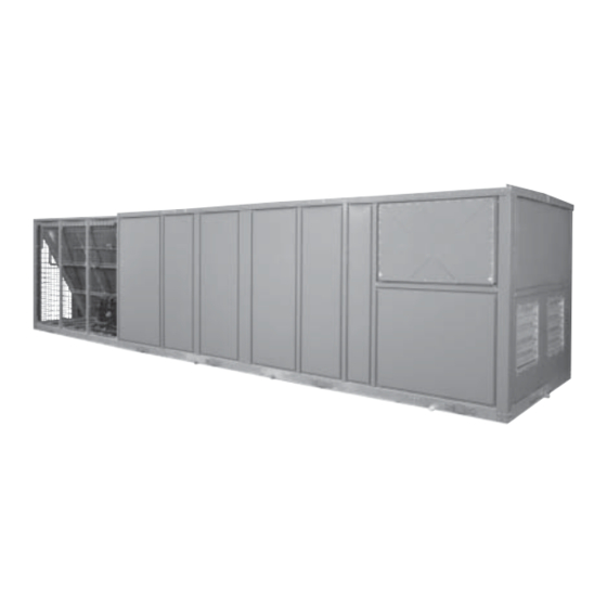
- Page 1 PACKAGED ROOFTOP AIR CONDITIONING UNITS New Release Form 100.50-SU3 (1207) QUICK START-UP GUIDE 035-21972-200 Packaged Rooftop Air Conditioning Units YPAL 050 YPAL 051 YPAL 060 YPAL 061 DESIGN LEVEL F SIMPLICITY CONTROL LD13271 ASHRAE 90.1 COMPLIANT...
-
Page 2: General Safety Guidelines
FORM 100.50-SU3 (1207) IMPORTANT! READ BEFORE PROCEEDING! GENERAL SAFETY GUIDELINES This equipment is a relatively complicated ap pa ra tus. which it is sit u at ed, as well as severe personal injury or Dur ing installation, operation, maintenance or service, death to them selves and people at the site. -
Page 3: Changeability Of This Document
Base Product Type Nominal Capacity Application Refrigerant Voltage Supply Return Design Special Openings Openings :YORK :50 Ton Capacity B :R-407C :208/3/60 X :Standard :Packaged Rooftop :50 Ton Capacity C :R-22 :230/3/60 S :Special :Air Cooled :60 Ton Capacity E :R-410A... -
Page 4: Table Of Contents
FORM 100.50-SU3 (1207) TABLE OF CONTENTS GENERAL SAFETY GUIDELINES ........................2 SAFETY SYMBOLS .............................2 CHANGEABILITY OF THIS DOCUMENT ......................3 NOMENCLATURE ...............................3 QUICK START GUIDE – YPAL UNITS ........................6 ALL UNITS ................................7 OCCUPIED / UNOCCUPIED – HARD WIRED .....................7 OCCUPIED / UNOCCUPIED – INTERNAL TIME CLOCK ................7 OCCUPIED / UNOCCUPIED –... - Page 5 FORM 100.50-SU3 (1207) TABLE OF CONTENTS (CON'T) PRE-OCCUPANCY PURGE ........................24 OUTDOOR AIR HEATING LOCKOUT ......................24 HOT GAS BYPASS .............................24 SPACE TEMPERATURE ALARM .......................24 SAT ALARM FOR HEATING ........................24 SAT ALARM FOR COOLING ........................25 INTELLI-START ............................25 SPACE SENSOR WITH SETPOINT ADJUSTMENT ..................25 REMOTE CONTROL ...........................25 DIRTY FILTER .............................25 METRIC OPERATION ..........................26...
-
Page 6: Quick Start Guide - Ypal Units
See Appendix 2 for directions on how to turn on the Factory Run Test feature as well as a description of the operation of the test sequence. * FlexSys VAV is YORK’s VAV Underfl oor Air Unit. JOHNSON CONTROLS... -
Page 7: All Units
FORM 100.50-SU3 (1207) ALL UNITS OCCUPIED / UNOCCUPIED – HARD WIRED OCCUPIED / UNOCCUPIED – BAS SYSTEM Field Wiring Field Wiring Field supplied contacts connected to terminals “R” and No connection between terminals “R” and “OCC” on “OCC” on the Simplicity control board. the Simplicity control board. -
Page 8: Constant Volume Units
FORM 100.50-SU3 (1207) CONSTANT VOLUME UNITS THERMOSTAT CONTROL – COOLING Programming “HEATING MODE OPERATION ENABLED” – Must Field Wiring be set to ON using Parameter 54 under the PROGRAM key on the Simplicity control board or under the Connect the thermostat wiring to the fi eld wiring screw HEATING SETUP tab in the Simplicity PC software connections on the Unit Controller (see Appendix 1). -
Page 9: Hardwired Or Communicated Space Sensor Control - Heating
FORM 100.50-SU3 (1207) “CV OCCUPIED COOLING SETPOINT” – Must be “STAGES OF HEATING AVAILABLE” - Must be set set using Parameter 10 under the PROGRAM key on using Parameter 81 under the PROGRAM key on the the Simplicity control board or under the COOLING Simplicity control board or under the HEATING SETUP SETUP tab in the Simplicity PC software package. -
Page 10: Stand Alone Control - Heating
FORM 100.50-SU3 (1207) STAND ALONE CONTROL – HEATING Field Wiring No additional connections required. Misc. Connections No additional connections required. Programming “HEATING MODE OPERATION ENABLED” – Must be set to ON using Parameter 54 under the PROGRAM key on the Simplicity control board or under the HEATING SETUP tab in the Simplicity PC software package. -
Page 11: Variable Air Volume Units
FORM 100.50-SU3 (1207) VARIABLE AIR VOLUME UNITS “VAV COOLING SUPPLY AIR TEMP LOWER THERMOSTAT CONTROL – COOLING SETPOINT” – Must be set using Parameter 24 under the PROGRAM key on the Simplicity control board or Field Wiring under the COOLING SETUP tab in the Simplicity PC software package. -
Page 12: Hardwired Or Communicated Space Sensor Control - Cooling
FORM 100.50-SU3 (1207) Programming “VAV OCCUPIED HEATING ENABLED” – Must be installed on the support post, and should be used to set to ON using Parameter 26 under the PROGRAM key connect the atmospheric probe using fi eld supplied on the Simplicity control board or under the HEATING pneumatic tubing. -
Page 13: Hardwired Or Communicated Space Sensor Control - Heating
FORM 100.50-SU3 (1207) “VAV OCCUPIED HEATING SETPOINT” – Must be HARDWIRED OR COMMUNICATED SPACE SENSOR CONTROL – HEATING set using Parameter 27 under the PROGRAM key on the Simplicity control board or under the HEATING SETUP tab in the Simplicity PC software package. Field Wiring Settable between 40.0º... -
Page 14: Stand Alone Control - Heating
FORM 100.50-SU3 (1207) An atmospheric static pressure probe with a bracket is “DUCT PRESSURE SETPOINT” – Must be set factory supplied (shipped in the return section of the using Parameter 30 under the PROGRAM key on the unit) and is to be installed on the specifi ed support post Simplicity control board or under the FAN tab in the (see Appendix 1). - Page 15 FORM 100.50-SU3 (1207) “VAV OCCUPIED HEATING SETPOINT” – Must be set using Parameter 27 under the PROGRAM key on the Simplicity control board or under the HEATING SETUP tab in the Simplicity PC software package. Settable between 40.0º F and 85.0º F. The default value is 68.0º...
-
Page 16: Options
FORM 100.50-SU3 (1207) OPTIONS ECONOMIZER – CONSTANT VOLUME – DRY Misc. Connections BULB No additional connections required. Field Wiring Programming No additional connections required. “ECONOMIZER INSTALLED” – must be turned ON using Parameter 32 under the PROGRAM key on the Misc. -
Page 17: Economizer - Variable Air Volume - Dry Bulb
FORM 100.50-SU3 (1207) Programming Programming “ECONOMIZER INSTALLED” – must be turned ON “ECONOMIZER INSTALLED” – must be turned ON using Parameter 32 under the PROGRAM key on the using Parameter 32 under the PROGRAM key on the Simplicity control board or under the ECONOMIZER/ Simplicity control board or under the ECONOMIZER/ EXHAUST tab in the Simplicity PC software. -
Page 18: Economizer -Variable Air Volume - Dual Enthalpy
FORM 100.50-SU3 (1207) “SUPPLY AIR TEMP LIMIT FOR COOLING” – must ECONOMIZER –VARIABLE AIR VOLUME – DUAL ENTHALPY be turned ON under the COOLING SETUP tab in the Simplicity PC software. “DUCT PRESSURE SETPOINT” – Must be set “SUPPLY AIR TEMP LIMIT COOLING SETPOINT” using Parameter 30 under the PROGRAM key on the –... -
Page 19: Fixed Minimum Ventilation
FORM 100.50-SU3 (1207) “ECONOMIZER MINIMUM POSITION” – must be FIXED MINIMUM VENTILATION programmed using Parameter 35 under the PROGRAM key on the Simplicity control board or under the Field Wiring ECONOMIZER/EXHAUST tab in the Simplicity PC software. The range is 0 – 100% with a default valve No additional connections required. -
Page 20: Excessive Supply Air Temperature Control (Cooling)
FORM 100.50-SU3 (1207) Programming EXCESSIVE SUPPLY AIR TEMPERATURE CONTROL (HEATING) “COMFORT VENTILATION FOR COOLING ENABLED” – must be turned ON under the COOLING Field Wiring SETUP tab in the Simplicity PC software. No additional connections required. “COMFORT VENTILATION FOR HEATING ENABLED”... -
Page 21: Hydronic Heat
FORM 100.50-SU3 (1207) “HYDRONIC HEATING STAGE #1 SUPPLY AIR Programming SETPOINT” – must be programmed using Parameter 19 under the PROGRAM key on the Simplicity control “ECONOMIZER INSTALLED” – must be turned ON board or under the HEATING SETUP tab in the using Parameter 32 under the PROGRAM key on the Simplicity PC software. -
Page 22: Exhaust Fan - On/Off Control Based On Outdoor Damper Position
FORM 100.50-SU3 (1207) An atmospheric static pressure probe with a bracket is EXHAUST FAN – ON/OFF CONTROL BASED ON OUTDOOR DAMPER POSITION factory supplied (shipped in the return section of the unit) and is to be installed on the specifi ed support post (see Appendix 1). -
Page 23: Exhaust - Modulating With A Vfd
FORM 100.50-SU3 (1207) An atmospheric static pressure probe with a bracket is EXHAUST – MODULATING WITH A VFD factory supplied (shipped in the return section of the unit) and is to be installed on the specifi ed support post Field Wiring (see Appendix 1). -
Page 24: Pre-Occupancy Purge
FORM 100.50-SU3 (1207) PRE-OCCUPANCY PURGE Misc. Connections No additional connections required. Field Wiring Programming No additional connections required. “ HOT GAS BY PASS PRESENT ON COMPRESSOR Misc. Connections #1” – must be turned ON using Parameter 79 under the PROGRAM key on the Simplicity control board No additional connections required. -
Page 25: Sat Alarm For Cooling
FORM 100.50-SU3 (1207) “SUPPLY AIR TEMP ALARM SETPOINT FOR Misc. Connections HEATING” – must be programmed under the HEATING SETUP tab in the Simplicity PC software. The range is No additional connections required. 1.0º F – 120.0º F. Entering 0º F disables the feature. Programming SAT ALARM FOR COOLING “SPACE SENSOR OFFSET RANGE”... -
Page 26: Metric Operation
FORM 100.50-SU3 (1207) Programming “DIRTY FILTER SWITCH INSTALLED” – Must be turned ON using Parameter 51 under the PROGRAM key on the Simplicity control board or under the EQUIPMENT INSTALLATION tab in the Simplicity PC software. METRIC OPERATION Field Wiring No additional connections. -
Page 27: Appendix 1 User Interface How To Program User Interface
FORM 100.50-SU3 (1207) APPENDIX 1 USER INTERFACE HOW TO PROGRAM USER INTERFACE UNIT CONTROLLER INTERFACE For example, the Occupied Cooling Setpoint is parameter Four buttons located on the control board allow for address 10. The addresses are listed on the Parameter viewing and access to setpoints, alarms, functions, Points list. -
Page 28: Test/Up Button
FORM 100.50-SU3 (1207) TEST/UP BUTTON When connected to a network, pressing the button twice When not in the program mode, if the Test/Up button within fi ve-seconds causes the network address to be is pushed and released once within fi ve seconds, the displayed for two seconds. - Page 29 FORM 100.50-SU3 (1207) TABLE 6-1 - PARAMETER POINTS LIST ADDRESS RANGE OF CURRENT DESCRIPTION UNITS OF ADJUSTMENT NUMBER ADJUSTMENT SETTING RUN TEST PARAMETER BIT 0 = OFF, 1 = ON HEAT FAN ON DELAY SECONDS 0-30 HEAT FAN OFF DELAY SECONDS 0-255 COOL FAN ON DELAY...
- Page 30 FORM 100.50-SU3 (1207) TABLE - 6-1 - PARAMETER POINTS LIST (CONT.) ADDRESS RANGE OF CURRENT DESCRIPTION UNITS OF ADJUSTMENT NUMBER ADJUSTMENT SETTING OUTSIDE AIR HUMIDITY SENSOR INSTALLED PARAMETER BIT 0 = OFF, 1 = ON ECONOMIZER OUTSIDE AIR ENTHALPY SETPOINT BTUS PER POUND 10 - 50 RETURN AIR HUMIDITY SENSOR INSTALLED...
- Page 31 FORM 100.50-SU3 (1207) TABLE - 6-1 - PARAMETER POINTS LIST (CONT.) ADDRESS RANGE OF CURRENT DESCRIPTION UNITS OF ADJUSTMENT NUMBER ADJUSTMENT SETTING 72/73/74/ ALARM ARRAY DATA - 5 CHARACTERS 0 - 255 75/76 CV = 0 VAV / CV SELECTION READ ONLY FLAG VAV = 1 HOT GAS REHEAT...
-
Page 32: Field Control Wiring Connections
FORM 100.50-SU3 (1207) FIELD CONTROL WIRING CONNECTIONS Wiring Notes: 1. Wiring shown indicates typical wiring. Refer to the IOM manual for more detailed wiring methods and options. 2. All wiring is Class 2, low voltage. 3. Maximum power available from the 24 VAVC terminal is 40 VA. 4. - Page 33 FORM 100.50-SU3 (1207) Filter Filter Compartment Compartment Economizer Economizer Compartment Compartment LD13127 FIG. 4 – ATMOSPHERIC SENSOR PROBE The atmospheric probe should be mounted on the support post on the control side of the unit between the Economizer and Filter Compartment. JOHNSON CONTROLS...
-
Page 34: Appendix 2 Factory Run Test Procedure
FORM 100.50-SU3 (1207) APPENDIX 2 FACTORY RUN TEST PROCEDURE RUN TEST SEQUENCE GENERAL The run test sequence is as follows: Each unit undergoes a fi nal QA check before the unit is shipped from the factory. This fi nal check includes •... - Page 35 FORM 100.50-SU3 (1207) • The Unit Controller will then send a 10 DCV analog signal to the Economizer Damper. This will place the outdoor damper in the full open position and place the return damper in the full closed position. The Unit Controller will also energize the binary output for the Exhaust Fan and send a 10 DCV signal to the Exhaust Damper if installed.
- Page 36 Tele. 800-861-1001 P.O. Box 1592, York, Pennsylvania USA 17405-1592 Subject to change without notice. Printed in USA Copyright © by Johnson Controls 2007 www.york.com ALL RIGHTS RESERVED Form 100.50-SU3 (1207) New Release...
Need help?
Do you have a question about the Eco 2 and is the answer not in the manual?
Questions and answers