Table of Contents
Advertisement
Quick Links
Original Operating Instructions
BATI0XXX-ES-1-XXX-1
Table of Contents
Original Operating Instructions
Battery Charger
BATI0XXX-ES-1-ZZZ-1
WSTECH is a Wind&Sun Technologies and Siemens Joint Venture.
Before starting any work, please read "Original Operating
Instructions" and "Interface Description Modbus TCP and
EtherCAT"!
O_BATI_0XXX-ES-1-ZZZ-1_V1.4_GB
Advertisement
Table of Contents

Related Manuals for WSTECH BATI0 Series


Summary of Contents for WSTECH BATI0 Series
- Page 1 Original Operating Instructions BATI0XXX-ES-1-XXX-1 Table of Contents Original Operating Instructions Battery Charger BATI0XXX-ES-1-ZZZ-1 WSTECH is a Wind&Sun Technologies and Siemens Joint Venture. Before starting any work, please read "Original Operating Instructions" and "Interface Description Modbus TCP and EtherCAT"! O_BATI_0XXX-ES-1-ZZZ-1_V1.4_GB...
-
Page 2: Table Of Contents
Original Operating Instructions BATI0XXX-ES-1-ZZZ-1 Table of Contents Table of Contents 1 User Information ................ 7 Identification of the Product................8 Scope ......................10 Target Audience ................... 10 General Information ..................10 1.4.1 Related Documents ................10 1.4.2 Symbols ....................11 1.4.3 Terms und Abbreviations ............... - Page 3 Original Operating Instructions BATI0XXX-ES-1-ZZZ-1 Table of Contents 3.4.1 AC Connection ..................30 3.4.2 DC Connection ..................32 3.4.3 Supply Voltage ..................33 3.4.4 Data Communication ................35 3.4.5 Option Island Grid Function ..............36 3.4.6 Customer Feedback AC Circuit Breaker (Optional) ........ 36 3.4.7 Customer Feedback Insulation Monitoring Device (Optional) ....
- Page 4 Original Operating Instructions BATI0XXX-ES-1-ZZZ-1 Table of Contents 7.1.1.1 Visual Inspection of Housing ............50 7.1.1.2 Visual Inspection of Interior Area ............ 50 7.1.1.3 Cleaning of Fan and Air Ducts ............50 7.1.1.4 Torque Check of Electrical Connections ......... 51 7.1.1.5 Check of Cable and Line Condition ..........
- Page 5 Original Operating Instructions BATI0XXX-ES-1-ZZZ-1 List of Figures List of Figures Figure 1: Example of the type plate (control cabinet) ............ 8 Figure 2: Example of the type plate (power unit) ............9 Figure 3: Example of an option plate ................9 Figure 4: Schematic structure of the power unit ............
- Page 6 Original Operating Instructions BATI0XXX-ES-1-ZZZ-1 List of Tables List of Tables Table 1: Complete naming ..................12 Table 2: Scope of delivery................... 22 Table 3: Operating mode of insulation monitoring device ..........37 Table 4: Abstract BATI Error Codes ................45 Table 5: Abstract BATI Error codes (continued) ............
-
Page 7: User Information
Original Operating Instructions BATI0XXX-ES-1-ZZZ-1 User Information 1 User Information Thank you for purchasing the BATI Battery Charger. By purchasing this WSTECH product, you have chosen a high-quality product. If you have still any questions, please contact WSTECH at info@wstech.com. Legal Information All rights reserved. -
Page 8: Identification Of The Product
Original Operating Instructions BATI0XXX-ES-1-ZZZ-1 User Information Identification of the Product The type plates and option plates are located outside at the bottom-right as well as inside of the doors. Figure 1: Example of the type plate (control cabinet) Pos. Description Manufacturer Product Hardware- and wiring diagram version... -
Page 9: Figure 2: Example Of The Type Plate (Power Unit)
Original Operating Instructions BATI0XXX-ES-1-ZZZ-1 User Information Figure 2: Example of the type plate (power unit) Pos. Description Manufacturer Product Hardware- and wiring diagram version Technical data DC connection Degree of protection Serial number Technical data AC connection Product identification WEEE identification Figure 3: Example of an option plate O_BATI_0XXX-ES-1-ZZZ-1_V1.4_GB Seite 9 von 60... -
Page 10: Scope
Original Operating Instructions BATI0XXX-ES-1-ZZZ-1 User Information Scope The original operating instructions (hereafter referred to as operating instructions) are valid for: • BATI0XXX-ES-1-ZZZ-1 CC (hardware version: 20X, wiring diagram version: 2.XX) • BATI0XXX-ES-1-ZZZ-1 PU (hardware version: 10X, wiring diagram version: 2.XX) The complete product consists of the control cabinet (CC) and one power unit (PU) is hereafter referred to as BATI0XXX. -
Page 11: Symbols
Original Operating Instructions BATI0XXX-ES-1-ZZZ-1 User Information 1.4.2 Symbols Symbol Description DANGER! Indicates a direct danger situation which can lead to death or severe injury. WARNING! Indicates a possible danger situation which can lead to death or severe injury. ATTENTION! Indicates a possible danger situation which can lead to lesser or lighter injury. -
Page 12: Terms Und Abbreviations
Original Operating Instructions BATI0XXX-ES-1-ZZZ-1 User Information 1.4.3 Terms und Abbreviations Table 1: Complete naming Complete naming Naming within Document Control cabinet Constant current – constant voltage CC-CV Electromagnetic compatibility Hardware version Insulated gate bipolar transistor IGBT International protection Mean sea level Position Pos. -
Page 13: Intended Use
Original Operating Instructions BATI0XXX-ES-1-ZZZ-1 User Information Intended Use This product is intended for use exclusively with batteries. It is used for converting the DC current supplied by battery into an AC current and vice versa. The BATI0XXX can operate in different operating modes. These modes are described in the Interface Description. -
Page 14: Safety Instructions
Original Operating Instructions BATI0XXX-ES-1-ZZZ-1 User Information Safety Instructions DANGER! Danger to life due to disregarding the instructions for action! Disregarding the safety instructions or performing unauthorized actions may lead to serious injury or death. • Read and observe all safety instructions and symbols on the product and within the operating instructions. -
Page 15: Product Safety Sign
Original Operating Instructions BATI0XXX-ES-1-ZZZ-1 User Information Product Safety Sign DANGER! Risk of electrical shock form energy stored in capacitors! Life hazard due to high voltage. • Wait minimum 30 minutes after shutdown before working on the product. The product safety sign is located on the cabinet doors (Figure 5). Cleaning DANGER! Danger to life due to fire or explosion! -
Page 16: Description
Original Operating Instructions BATI0XXX-ES-1-ZZZ-1 Description 2 Description Functional Description The product is developed for charging and discharging batteries and equipped with modern efficiency optimized technology. It works on low voltage level. The product is usable for IT-grid only. Principle of the Product The product can feed, power controlled, the energy stored in batteries into the grid. -
Page 17: Figure 4: Schematic Structure Of The Power Unit
Original Operating Instructions BATI0XXX-ES-1-ZZZ-1 Description Figure 4: Schematic structure of the power unit O_BATI_0XXX-ES-1-ZZZ-1_V1.4_GB Seite 17 von 60... -
Page 18: Options
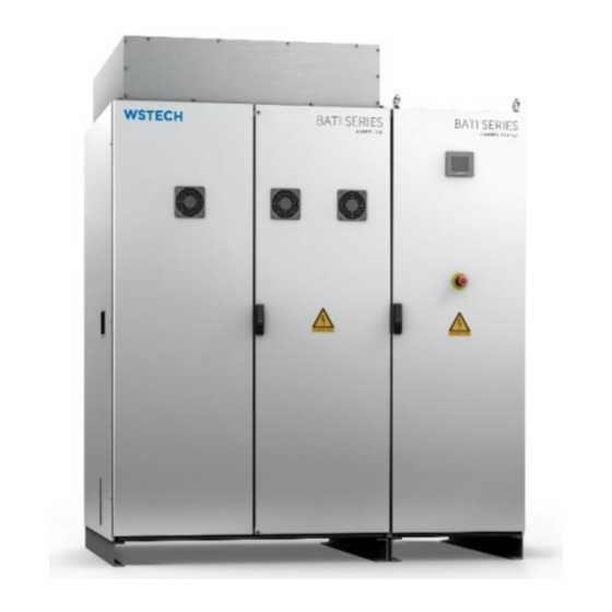
Original Operating Instructions BATI0XXX-ES-1-ZZZ-1 Description Options Following options are available: • Island grid function • Cabinet heating • EtherCAT interface Views The illustrations used in these operating instructions are reduced to the essentials and may differ from the delivered product. 2.4.1 Exterior View The product consists of two cabinets (Figure 5). -
Page 19: Interior Views
Original Operating Instructions BATI0XXX-ES-1-ZZZ-1 Description 2.4.2 Interior Views 2.4.2.1 Interior View Control Cabinet Figure 6 shows the front interior view of the control cabinet. Pos. Description Control card (-A1, -A2) Thermostat (-BT1) Customer interface terminal strip (-X15) Customer interface terminal strip (-X2) Customer interface terminal strip (-X16) Connection supply voltage for... -
Page 20: Figure 7: Miniature Circuit Breaker
Original Operating Instructions BATI0XXX-ES-1-ZZZ-1 Description Figure 7: Miniature circuit breaker Pos. Item Components designation Fan (located in PU) Power supply for fans CC and PU -F13 230 V supply voltage for switches (-Q1) and (-Q2) (located in PU) and 230 V supply voltage for insulation monitoring device (located in CC) -F14... -
Page 21: Interior View Power Unit
Original Operating Instructions BATI0XXX-ES-1-ZZZ-1 Description 2.4.2.2 Interior View Power Unit Figure 8: Interior view front power unit Pos. Description Main fan Power Stacks Overvoltage protection (-F4) Fuse switch disconnector Harmonic filter (-F3) DC switch disconnector (-Q1) Fuse insulation monitoring device (-F1) Fuse pre-charge circuit (-F10) Fuse pre-charge circuit (-F11) Fuse voltage measurement (-F2) -
Page 22: Installation
Original Operating Instructions BATI0XXX-ES-1-ZZZ-1 Installation 3 Installation NOTICE Damage to the product due to lightning! The product has NO lightning protection system. Absence of a lightning protection system can cause damage. • The risk of lightning damage can be reduced by installing a lightning protection system. -
Page 23: Transport
Original Operating Instructions BATI0XXX-ES-1-ZZZ-1 Installation Transport WARNING! Danger to life due to falling objects! The product can fall or tip over when transported incorrectly, which may cause damage to the product and result in serious injury or death to individuals within the products vicinity. •... -
Page 24: Transport With Crane
Original Operating Instructions BATI0XXX-ES-1-ZZZ-1 Installation 3.2.2 Transport with Crane Transport requirements: • Each cabinet of the product must be transported separately. • Make sure that the lifting lugs (see separate package) are permanently mounted. • Observe the weight of the product (Section 11.2.2). •... -
Page 25: Installation Site
Original Operating Instructions BATI0XXX-ES-1-ZZZ-1 Installation Installation Site 3.3.1 Installation Site Requirements 3.3.1.1 Environment Variables Temperature, air humidity and air quality as well as all further details about the installation site must comply with the conditions mentioned in section 11.2.2. 3.3.1.2 Foundation The foundation must be able to support the weight of the product and the transport vehicle (Section 11.2.2). -
Page 26: Mounting Points
Original Operating Instructions BATI0XXX-ES-1-ZZZ-1 Installation 3.3.2 Mounting Points Figure 10 shows the mounting points of the product. For each cabinet 4 screws are required to fix the product to the foundation. Figure 10: Mounting points BATI0XXX (bottom view) O_BATI_0XXX-ES-1-ZZZ-1_V1.4_GB Seite 26 von 60... -
Page 27: Electrical Connections
Original Operating Instructions BATI0XXX-ES-1-ZZZ-1 Installation Electrical Connections DANGER! Danger to life due to electric shock! An incorrect selection and cable routing can cause damages to property or personnel. • Selection and installation of electrical equipment, cable and lines comply to local rules and requirements. •... -
Page 28: Figure 11: Connection Area
Original Operating Instructions BATI0XXX-ES-1-ZZZ-1 Installation Figure 11: Connection area Pos. Connection DC connection AC connection Customer interfaces: (-X2.1-3): Customer feedback product (-X2.4-5): Customer switch (bridge must be removed, if a switch is connected) (-X2.6-8): Customer feedback insulation monitoring device (-X2.9-10): Voltage detection island grid function or grid feeding (-X2.11-13): Customer feedback AC circuit breaker Supply voltage 230 V Customer feedback Harmonic and Notch-filter fuses (optional) - Page 29 Original Operating Instructions BATI0XXX-ES-1-ZZZ-1 Installation For following connections, the cables / lines must be prepared, safe and de-energized: • AC connection (Section 3.4.1) • DC connection (Section 0) • Supply voltage connection (Section 3.4.3) • Data communication: 1 x Ethernet (Section 3.4.4) •...
-
Page 30: Ac Connection
Original Operating Instructions BATI0XXX-ES-1-ZZZ-1 Installation 3.4.1 AC Connection WARNING! Danger to life due to electric shock! The product must be grounded at the earthing bolt to establish a potential equalization. • Provide earth connection before connecting to the AC/DC power. NOTICE Connection with incorrect phase sequence causes errors when connecting to the grid! -
Page 31: Figure 12: Ac Connection
Original Operating Instructions BATI0XXX-ES-1-ZZZ-1 Installation Figure 12: AC connection Pos. Description AC circuit breaker (-Q2) PE connection Protective cover O_BATI_0XXX-ES-1-ZZZ-1_V1.4_GB Seite 31 von 60... -
Page 32: Dc Connection
Original Operating Instructions BATI0XXX-ES-1-ZZZ-1 Installation 3.4.2 DC Connection Procedure: Remove the sliding ground plate. Dismount the protective cover. Check cable feeds for damage. Connect the DC (+) and DC (–) cable onto the busbar of the DC switch disconnector (Figure 13). NOTICE: The cable lug must be suitable for a M12 screw. -
Page 33: Supply Voltage
Original Operating Instructions BATI0XXX-ES-1-ZZZ-1 Installation 3.4.3 Supply Voltage The product is operated with a supply voltage of 230 V/TN-grid. Requirements: • Supply lines must be connected and secured by means of a 16 A miniature circuit breaker with a tripping characteristic B or a 16 A fuse with a tripping characteristic gG. - Page 34 Original Operating Instructions BATI0XXX-ES-1-ZZZ-1 Installation Variant 2: Unbuffered supply voltage Procedure: Remove the sliding ground plate. Bridge terminals: (–X9.1) (–X9.2) (–X9.3) (–X9.4) Connect PE, L and N conductor of the unbuffered supply voltage to terminal strip (–X9): PE conductor (-X9.5) L conductor ...
-
Page 35: Data Communication
Original Operating Instructions BATI0XXX-ES-1-ZZZ-1 Installation 3.4.4 Data Communication NOTICE Damage of the product due to overvoltage! Overvoltage can be generated by lightning, by capacitive or inductive interference of other electric systems. • Ensure that a surge arrester is available, if an Ethernet cable is led outwards. -
Page 36: Option Island Grid Function
Original Operating Instructions BATI0XXX-ES-1-ZZZ-1 Installation 3.4.5 Option Island Grid Function This function is only available if the option island grid function is purchased. In delivery state the function is activated. To change to the grid feeding modus a supply voltage of +24V on terminal (-X2.9-10) is necessary. -
Page 37: Customer Feedback Insulation Monitoring Device (Optional)
Original Operating Instructions BATI0XXX-ES-1-ZZZ-1 Installation 3.4.7 Customer Feedback Insulation Monitoring Device (Optional) The product offers the possibility to evaluate the feedback contact of the insulation monitoring device by the customer. The connection is provided as potential-free contact at the terminal strip (-X2). Mode of operation of the insulation monitoring device: If the measured value drops below the set threshold value, the output relays switch into the fault state. -
Page 38: Customer Feedback Harmonic And Notch Filter Fuse
Original Operating Instructions BATI0XXX-ES-1-ZZZ-1 Installation 3.4.10 Customer Feedback Harmonic and Notch Filter Fuse The status of the Harmonic- and Notch filter fuses can be queried via terminal strip (–X16). The terminal strip is in the control cabinet (Figure 18). Figure 18: Customer feedback harmonic and notch filter fuses Condition Terminal Contact... -
Page 39: Operation
Original Operating Instructions BATI0XXX-ES-1-ZZZ-1 Operation 4 Operation WARNING! Danger to life due to high voltage! Risk of injury by disregarding the instructions for actions! • Read and observe all safety instructions and symbols on the product and within the operating instructions. •... -
Page 40: Figure 19: Danger Area
Original Operating Instructions BATI0XXX-ES-1-ZZZ-1 Operation Figure 19: Danger area O_BATI_0XXX-ES-1-ZZZ-1_V1.4_GB Seite 40 von 60... -
Page 41: Commissioning
Original Operating Instructions BATI0XXX-ES-1-ZZZ-1 Commissioning 5 Commissioning NOTICE Damage due to incorrect commissioning! Incorrect commissioning can damage the product. • „Interface Activating the product via the interfaces is described in Description Modbus TCP and EtherCAT“. NOTICE Damage to measuring device due to overvoltage! Performing measurements with the incorrect measuring range can cause damages. -
Page 42: Starting The Product
Original Operating Instructions BATI0XXX-ES-1-ZZZ-1 Commissioning Starting the Product WARNING! Risk of injury due to high voltage when measuring! Danger to life due to high voltage. • Take measurements only with appropriate measurement devices. • During measurement, the AC circuit breaker must be turned off and all fuse inserts must be removed. -
Page 43: Stopping The Product
Original Operating Instructions BATI0XXX-ES-1-ZZZ-1 Commissioning Stopping the Product DANGER! Danger to life due to high voltage! Even after stopping the product dangerous voltages are still present. • After stopping the product, observe a minimum wait time of at least 30 minutes prior to opening. •... -
Page 44: Troubleshooting
Original Operating Instructions BATI0XXX-ES-1-ZZZ-1 Troubleshooting 6 Troubleshooting DANGER! Danger to life due to high voltage! In case of fault, high voltage may still be present on the product. Touching energized parts leads to death or severe injury. • Observe all safety instructions when working on the product. WARNING! Risk of injury due to improper condition of the product! Incorrect troubleshooting can lead to serious bodily injury or death and... -
Page 45: Bati Error Codes
Original Operating Instructions BATI0XXX-ES-1-ZZZ-1 Troubleshooting BATI Error Codes Table 4: Abstract BATI Error Codes Code Error Description Corrective Action temperature_high_L1_HW Check cooling temperature_high_L2_HW Check cooling temperature_high_L3_HW Check cooling temperature_high_PT100_X108A12 Check cooling temperature_high_PT100_X108A34 Check cooling temperature_high_PT100_X108B12 Check cooling temperature_high_PT100_X108B34 Check cooling temperature_high_board Check cooling temperature_low_L1_SW... -
Page 46: Bati Error Codes 11, 13, 15, 17-21
Original Operating Instructions BATI0XXX-ES-1-ZZZ-1 Troubleshooting Table 5: Abstract BATI Error codes (continued) Code Error Description Corrective Action OV-Protection_/_Filter_Fuses Check OV-Protection Insulation Error Check Insulation Inverter_HW_Error_L1 Check Powerstack Inverter_HW_Error_L2 Check Powerstack Inverter_HW_Error_L3 Check Powerstack Port_Idc_error Check Idc-Sensor connection Precharge_DC-Link Check Precharge circuit Check DC-Source Grid_rotation Check gird rotation... -
Page 47: Bati Error Code 157
Original Operating Instructions BATI0XXX-ES-1-ZZZ-1 Troubleshooting 6.1.6 BATI Error Code 157 Corrective action: It is recommended to replace all surge arresters, if the indication shows a red flag. Surge arrester (–F4) is located is in the power unit (Figure 8) ... -
Page 48: Bati Warning Codes
Original Operating Instructions BATI0XXX-ES-1-ZZZ-1 Troubleshooting BATI Warning Codes Table 1: Abstract BATI Warning Codes Code Warning Description Corrective Action temperature_high_L1 Reduce power / check cooling temperature_high_L2 Reduce power / check cooling temperature_high_L3 Reduce power / check cooling temperature_high_PT100_X108A12 Reduce power / check cooling temperature_high_PT100_X108A34 Reduce power / check cooling temperature_high_PT100_X108B12... -
Page 49: Maintenance
Original Operating Instructions BATI0XXX-ES-1-ZZZ-1 Maintenance 7 Maintenance DANGER! Danger to life due to high voltage! Even after stopping the product dangerous voltages are present in the product. Touching live parts can result in death or serious injury due to electric shock. •... -
Page 50: Annual Maintenance
Original Operating Instructions BATI0XXX-ES-1-ZZZ-1 Maintenance Procedure: 1. Set product operation mode to OFF via the user interface (Section 8). NOTICE: To switch off the product from the AC/DC power, the AC/DC cables must be externally disconnected from the product and secured from being switched on again. Annual Maintenance NOTICE: During each maintenance interval, the following point must be checked. -
Page 51: Torque Check Of Electrical Connections
Original Operating Instructions BATI0XXX-ES-1-ZZZ-1 Maintenance 7.1.1.4 Torque Check of Electrical Connections Maintenance tasks: a. Open doors. b. Check connections and connectors of all parts for tightness. If connections are loose, please contact customer service (Section 10). Tighten with specific torque. c. -
Page 52: Functional Test Of Ac Circuit Breaker
Original Operating Instructions BATI0XXX-ES-1-ZZZ-1 Maintenance 7.1.1.8 Functional Test of AC Circuit Breaker Maintenance tasks: a. Open doors. b. Check the continuity of the AC circuit breaker (-Q2) when it is switched on. If the AC circuit breaker has no continuity, replace it. c. -
Page 53: Decommissioning
Original Operating Instructions BATI0XXX-ES-1-ZZZ-1 Decommissioning 8 Decommissioning Procedure: Stop the product (Section 5.3). Switch off the AC/DC voltage externally and secure from being switched on again. Disconnect the AC/DC cables. Ensure that no residual voltage is still present within the DC link (Figure 19) by means of suitable testing equipment. -
Page 54: Disposal
Original Operating Instructions BATI0XXX-ES-1-ZZZ-1 Disposal 9 Disposal The product contains electrical components and metals. Final and professional disposal of the product must be executed by the customer under the applicable statutory regulations of the country in which the product is used. Please observe the special regulations for electric and electronic equipment in particular. -
Page 55: Customer Service
• Failure description: Inverter status, Failure date, Error code, Detailed failure description How often does the error occur? Address WSTECH GmbH Eckernförder Landstraße 78 D-24941 Flensburg, Germany Telephone +49-(0) 461-430122-69 Fax: +49-(0) 461-430122-11 E-mail service@wstech.com Internet www.wstech.com... -
Page 56: Appendix
Original Operating Instructions BATI0XXX-ES-1-ZZZ-1 Appendix 11 Appendix 11.1 Spare Parts Item Part no. Article Type Quantity designation description -F3 (in PU) 500335 NH-Fuse NH00 690 V / 40 A -F2 (in PU) 500032 Fuse 0,44A/1000V, 10x38 mm -F1 (in PU) 500032 Fuse 0,44A/1000V, 10x38 mm... -
Page 57: Technical Data
Original Operating Instructions BATI0XXX-ES-1-ZZZ-1 Appendix 11.2 Technical Data 11.2.1 Electrical Data Table 7: Electrical data BATI0600-ES-1-270-1 BATI0720-ES-1-300-1 BATI0900-ES-1-380-1 Remarks AC SIDE Max. rated apparent power 600 kVA 720 kVA 900 kVA At rated grid voltage At (cos (φ)) = 1.0 Rated active power 500 kW 615 kW... -
Page 58: General Data
Original Operating Instructions BATI0XXX-ES-1-ZZZ-1 Appendix 11.2.2 General Data Table 8: General data BATI0600-ES-1-270-1 BATI0720-ES-1-300-1 BATI0900-ES-1-380-1 Remarks 0 °C…50 °C Ambient temperature Others on request Max. humidity < 95 % Not condensing Max. altitude above sea level 1500 m Without derating in power Cooling type Forced air Air cooling volume... -
Page 59: Eu Declaration Of Conformity
Original Operating Instructions BATI0XXX-ES-1-ZZZ-1 Appendix 11.3 EU Declaration of Conformity O_BATI_0XXX-ES-1-ZZZ-1_V1.4_GB Seite 59 von 60...
Need help?
Do you have a question about the BATI0 Series and is the answer not in the manual?
Questions and answers