Table of Contents
Advertisement
Quick Links
Advertisement
Table of Contents

Related Manuals for Baumer DENEX Gripper LED


Summary of Contents for Baumer DENEX Gripper LED
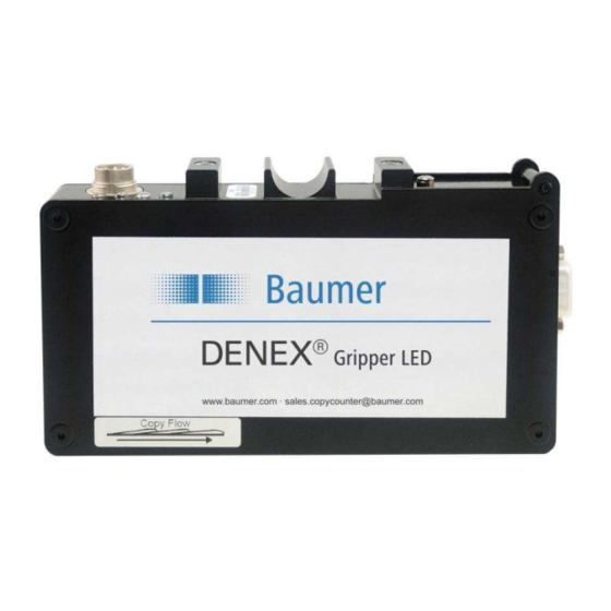
- Page 1 USER MANUAL FOR DENEX VERSIONS: 2009 ® DENEX Gripper LED FLDM 180C1101/S42...
- Page 2 Always turn off the sensor before moving or adjusting it. The DENEX Gripper LED must be applied, installed, adjusted, and maintained only by qualified personnel who are familiar with the operation of the DENEX Gripper LED and its associated components.
-
Page 3: Table Of Contents
The STATUS- LED _____________________________________________________ 14 TECHNICAL SPECIFICATIONS ______________________________________ 15 ACCESSORIES AVAILABLE FROM DENEX ___________________________ 16 Conversion kits _______________________________________________________ 16 9.1.1 Exchanging Ferag-Finger with Baumer proximity switch _____________ 16 MAINTENANCE AND REPAIRS _____________________________________ 17 10.1 Maintenance at Regular Intervals _____________________________________ 17 RETURNING EQUIPMENT _________________________________________ 17... -
Page 4: Introduction
BASIC FUNCTION The DENEX Gripper LED is a non-contact sensor which counts all kinds of products carried in a Gripper. It senses the leading edge and generates one output pulse for every product. -
Page 5: Installation
Check that the LED 4 indicates Target Status OK, see chapter 6, ”SOFTWARE FUNCTIONS”. Failure to comply will make the counter less accurate. Mount the DENEX Gripper LED as close as possible to the Grippers without risking being in contact with the Grippers. A 5 mm safety distance is recommended. - Page 6 GRIPPER LED Min 30 mm Rec 50-60 mm 120-150 mm Support bars Target plate Figure 4.2.2 Installing the sensor on a Ferag TTR Gripper conveyor. User Manual DENEX Gripper LED 6/24 Baumer Electric AG Version 2013-02, V1.4 www.baumer.com Frauenfeld, Switzerland...
-
Page 7: Electrical Installation
“DIP-Switch Settings” in chapter 6.4. The specification for the output opto-coupler is as follows: Max load current: 150mA Max voltage: 35V DC User Manual DENEX Gripper LED 7/24 Baumer Electric AG Version 2013-02, V1.4 www.baumer.com Frauenfeld, Switzerland... -
Page 8: Output Signal - Connections
Figure 5.2.1.2 Electrical connection, common 24VDC-supply. Current sink (NPN). Copy Sensor DENEX CopySensor™ Control system/Stacker/Totalizer Examples of input stage +24V Figure 5.2.1.3 Electrical connection, separate supply for power and pulse. User Manual DENEX Gripper LED 8/24 Baumer Electric AG Version 2013-02, V1.4 www.baumer.com Frauenfeld, Switzerland... -
Page 9: Speed Sensor Input
However, the principle is the same; when a Gripper is close to the switch, it will change status on the output. The DENEX Gripper LED will sense this change and use it in the Blocking Function routine. See chapter 6, ”SOFTWARE FUNCTIONS”. -
Page 10: Software Functions
Before actual settings are discussed, first a short description of the major functions and terms. Mode Setting The DENEX Gripper LED has a Single Production Mode and a Double Production Mode. The difference is the Blocking Zone, see below. There are also modes for replacement of mechanical fingers There are four DIP-switches that tell the sensor which application it should be set for. -
Page 11: Gripper Pulse Mode
Gripper pulse to the speed sensor input. This is a signal which is normally available in Gripper conveyors. Normally it is a proximity switch which senses each Gripper. This pulse can be connected to the input on the DENEX Gripper LED as described in chapter 4. With DIP-switches the Gripper Pulse Mode is selected. - Page 12 • You can also check with a scope, either on the Output directly or between TP8 and TP1, see chapter 6. If this is done OK, the sensor will only count one edge for half a Gripper, which will be the ideal situation. User Manual DENEX Gripper LED 12/24 Baumer Electric AG Version 2013-02, V1.4 www.baumer.com...
-
Page 13: Dip-Switch Settings
Speed sensor status Lit when target is recognized by sensor Lit when target is recognized by sensor Lit when target is recognized by sensor Not applicable User Manual DENEX Gripper LED 13/24 Baumer Electric AG Version 2013-02, V1.4 www.baumer.com Frauenfeld, Switzerland... -
Page 14: Led Indicators
6.4, ”DIP-Switch Settings”. By watching this LED, it is fairly easy to see that the sensor is giving the correct amount of pulses. The STATUS- LED see chapter 6, ”SOFTWARE FUNCTIONS”. User Manual DENEX Gripper LED 14/24 Baumer Electric AG Version 2013-02, V1.4 www.baumer.com... -
Page 15: Technical Specifications
175 x 96 x 31mm, 6.89 x 3.78 x 1.22” Power 24 V DC. 230 mA typical Temp. Range +10 to 40ºC, 50 to 104ºF User Manual DENEX Gripper LED 15/24 Baumer Electric AG Version 2013-02, V1.4 www.baumer.com Frauenfeld, Switzerland... -
Page 16: Accessories Available From Denex
Check the type (NPN or PNP) of Baumer that is used. Wire according to chapter 5. • If the output is inactive (0V on the output) when no papers are present and the Baumer is inactive when no Gripper is close to it Use Mode 2. -
Page 17: Maintenance And Repairs
• Check that the target is mounted the way it should be 11 RETURNING EQUIPMENT If it is necessary to return a DENEX Gripper LED for repair, the following procedure should be followed. 1. Tag the unit with the following: •... -
Page 18: Warranty
12 WARRANTY Baumer Electric AG gives a warranty to the customer for quality and suitability of its products within the scope of its technical specifications. A warranty is only given according to prior agreement for parts which are used as safety parts within the meaning of the EU Machinery Directive. -
Page 19: Troubleshooting
The sensor does not read the Speed Sensor Input Signal • Check polarity and levels according to chapter 5.2.2, ”Speed Sensor Input”. Is the speed very high? It should be max. 2.5 kHz. User Manual DENEX Gripper LED 19/24 Baumer Electric AG Version 2013-02, V1.4 www.baumer.com... - Page 20 If in Gripper Pulse Mode, it is extremely important that the Gripper Pulse is received for every Gripper on the chain. Check the installation of the DENEX Gripper LED and the proximity switch. The output pulse duty cycle should be approximately 50 %.
-
Page 21: Appendix
14 APPENDIX Ferag TTR Finger to DENEX Gripper LED Conversion kit Ferag UTR Finger to DENEX Gripper LED Conversion kit A 1: Conversion kit: Ferag TTR finger to Gripper LED. Part no. 11084181 This conversion kit will provide an easy to install solution when replacing the mechanical finger in Ferag TTR conveyors with the non-contact DENEX Gripper LED. - Page 22 A2: Conversion kit: Ferag UTR finger to Gripper LED. Part no. 11084159 This conversion kit will provide an easy to install solution when replacing the mechanical finger in Ferag UTR conveyors with the non-contact DENEX Gripper LED. Replace the mechanical finger from this To the DENEX solution: •...
-
Page 23: Supplements
15 Supplements User Manual DENEX Gripper LED 23/24 Baumer Electric AG Version 2013-02, V1.4 www.baumer.com Frauenfeld, Switzerland... - Page 24 Hummelstrasse 17 CH - 8500 Frauenfeld Phone +41 (0) 527281122 Fax +41 (0) 527281110 sales.copycounter@baumer.com www.baumer.com Technical data subject to change Printed in Switzerland No. 11084086 User Manual DENEX Gripper LED 24/24 Baumer Electric AG Version 2013-02, V1.4 www.baumer.com Frauenfeld, Switzerland...
Need help?
Do you have a question about the DENEX Gripper LED and is the answer not in the manual?
Questions and answers