Advertisement
Quick Links
Advertisement

Related Manuals for DMX4ALL DMX-Universal-Demux


Summary of Contents for DMX4ALL DMX-Universal-Demux
- Page 1 DMX-Universal-Demux User Manual...
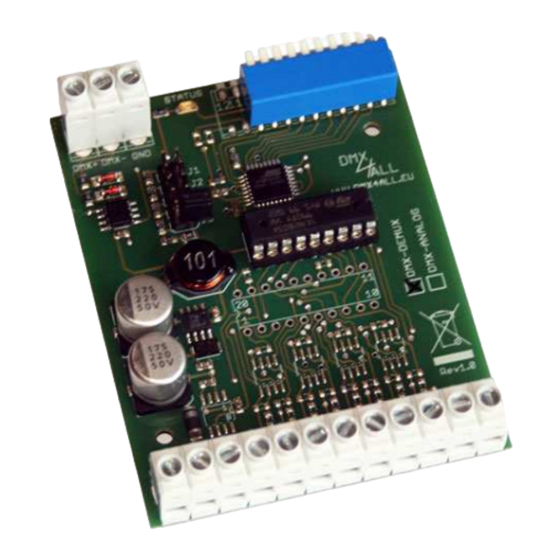
- Page 2 By jumper the operating mode of the DMX-Universal-Demux can be selected. Available are the operation modes Threshold / Binär / PWM / Servo / Strobo. Controllable via DMX The DMX-Universal-Demux is controlled by DMX and uses 1 or 8 DMX channels depending on the operating mode. LED status display The LED status display shows the DMX reception.
-
Page 3: Data Sheet
DMX-Universal-Demux Data sheet Supply voltage: 7-24V DC Current consumption: 40mA@12V / 35mA@24V (without load) DMX-Input: 1 or 8 DMX-Channels (depends on selected mode) Output: 8 open-collector outputs max. 500mA Operation mode: Threshold (switches at 50%) Binary (8-Bit) (~175Hz) Servo Strobo... - Page 4 DMX-Universal-Demux Connection...
-
Page 5: Led Display
DMX-Universal-Demux Addressing The starting address is adjustable via a DIP-Switch. Switch 1 has the valency 2 (=1), switch 2 has the valency 2 (=2) and so on… finally switch 9 has the valency 2 (=256). The sum of the switches showing ON, represents the starting address. -
Page 6: Operation Mode
DMX-Universal-Demux Operation mode The operation mode is selectable via a jumper. It is important to place the jumper in accordance to the following drawings to ensure a clean function. It is not possible to combine the modes. Treshold value-output (no jumper placed) In the mode “Treshold value”... - Page 7 Output 8: 11011011 To invert the output-signal please use switch 10. Strobe-Control (only jumper J2 is placed) The DMX-Universal-Demux outputted 8 controlling signals for stroboscope in the strobe-control-mode. Thereby each output will be triggered with one DMX- Channel. The DMX-Value assignment is as follows:...
- Page 8 The PWM-Frequency is ca. 175 Hz. To invert the output-signal please use switch 10. Servo-Control (only jumper J4 is placed) The DMX-Universal-Demux receives 8 successive DMX-Channels and outputted a signal for triggering customary Servos. Thereby each output will be used to trigger one Servo.
- Page 9 DMX-Universal-Demux Equipment Top-hat rail housing 700 Power supply 12V / 20W...
- Page 10 DMX-Universal-Demux CE-Conformity This assembly (board) is controlled by a microprocessor and uses high frequency. In order to maintain the properties of the module with regard to CE conformity, installation into a closed metal housing in accordance with the EMC directive 2014/30/EU is necessary.
- Page 11 Germany Last changes: 12.02.2019 © Copyright DMX4ALL GmbH All rights reserve. No part of this manual may be reproduced in any form (photocopy, pressure, microfilm or in another procedure) without written permission or processed, multiplied or spread using electronic systems.
Need help?
Do you have a question about the DMX-Universal-Demux and is the answer not in the manual?
Questions and answers