Table of Contents
Advertisement
Quick Links
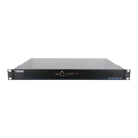
Central Power Hub
Modular power source for up to sixteen devices,
with remote management and optional redundant
operation.
Order toll-free in the U.S. or for FREE technical support 24/7: Call 877-877-BBOX
Customer
(outside U.S. call 877-877-2269)
Support
www.blackbox.com • info@ blackbox.com
Information
ACR1000-CPH8R
ACR1000-12V5-CBL2M
ACR1000-CPH16R
ACR1000-3PL-CBL2M
ACR1000-CPH-PS
Advertisement
Table of Contents

Subscribe to Our Youtube Channel
Related Manuals for Black Box ACR1000-CPH8R


Summary of Contents for Black Box ACR1000-CPH8R
- Page 1 ACR1000-CPH8R ACR1000-CPH16R ACR1000-12V5-CBL2M ACR1000-3PL-CBL2M ACR1000-CPH-PS Central Power Hub Modular power source for up to sixteen devices, with remote management and optional redundant operation. Order toll-free in the U.S. or for FREE technical support 24/7: Call 877-877-BBOX Customer (outside U.S. call 877-877-2269) Support www.blackbox.com •...
- Page 2 Central Power Hub Trademarks Used in this Manual Black Box and the Double Diamond logo are registered trademarks of BB Technologies, Inc. Any other trademarks mentioned in this manual are acknowledged to be the property of the trademark owners. We‘re here to help! If you have any questions about your application or our products, contact Black Box Tech Support at 877-877-2269 or go to blackbox.com and click on “Talk to Black Box.”...
- Page 3 FCC and IC RFI Statements Federal Communications Commission and Industry Canada Radio Frequency Interference Statements This equipment generates, uses, and can radiate radio-frequency energy, and if not installed and used properly, that is, in strict accordance with the manufacturer’s instructions, may cause inter ference to radio communication. It has been tested and found to comply with the limits for a Class A computing device in accordance with the specifications in Subpart B of Part 15 of FCC rules, which are designed to provide reasonable protection against such interference when the equipment is operated in a commercial environment.
- Page 4 Central Power Hub Instrucciones de Seguridad (Normas Oficiales Mexicanas Electrical Safety Statement) 1. Todas las instrucciones de seguridad y operación deberán ser leídas antes de que el aparato eléctrico sea operado. 2. Las instrucciones de seguridad y operación deberán ser guardadas para referencia futura. 3.
-
Page 5: Table Of Contents
Table of Contents Contents 1. Specifications ....................................6 1.1 Options ..................................... 6 2. Welcome ....................................7 2.1 Protection and control ............................... 7 2.2 5VDC converter dongles ..............................7 3. Installation ....................................8 3.1 Mounting converter dongles ............................. 8 3.2 Connections ..................................9 3.3 Fitting/removing a power module ...........................11 3.4 Network connection ................................12 4. -
Page 6: Specifications
Operating Temperature: 32 to 104°F (0 to 40°C) 1.1 Options The following options are available: • Central power hub unit with 8 output ports Part number: ACR1000-CPH8R • Central power hub unit with 16 output ports Part number: ACR1000-CPH16R • 5VDC converter dongle with 6.5' (2m) lead Part number: ACR1000-12V5-CBL2M •... -
Page 7: Welcome
Each power output port operates at 12VDC. For devices that use 12VDC, a simple connection cable (ACR1000-3PL-CBL2M) is all that’s required to link them to each power port. However, numerous Black Box devices operate at a lower voltage of 5VDC and these each require the use of a converter dongle (ACR1000-12V5-CBL2M) to take the place of the simple connection cable. -
Page 8: Installation
Central Power Hub 3. Installation Please consider the following important points when planning the position of the Central Power Hub unit: • The Central Power Hub main chassis occupies a single 1U (19”) rack slot and requires either one or two (when the redundancy option is used) mains inputs. -
Page 9: Connections
Chapter 3: Installation 3.2 Connections The multiple output ports of the Central Power Hub each provide power at 12VDC; when ACR1000-3PL-CBL2M link cable powering a 12VDC device, you merely need to use a basic cable (part number: ACR1000- 3PL-CBL2M). However, if you need to power a 5VDC device, you must use a converter don- gle (part number: ACR1000-12V5-CBL2M). - Page 10 Central Power Hub 3.2.3 Connecting a 5V device Devices that require a 5VDC supply require the use of a Converter dongle to form the link between the Central Power Hub port and the device, while also transforming the voltage level. Each converter dongle has two leads: a 2.5mm power jack and a lock- ing Kycon®...
-
Page 11: Fitting/Removing A Power Module
Chapter 3: Installation 3.3 Fitting/removing a power module The Central Power Hub main chassis can accommodate two power modules, although operation is perfectly possible with just one module fitted. The addition of a second module provides redundancy for critical installations. IMPORTANT: To ensure correct and reliable operation, only approved power modules may be used with the Central Power Hub. -
Page 12: Network Connection
Central Power Hub 3.4 Network connection The Central Power Hub allows remote monitoring and control via a standard network connection. Note: The patch cable used to link with the Central Power Hub must be screened to the S/FTP level. 3.4.1 To connect to a network 1 Use a screened patch cable (cross-over or straight connections are both sup- ported) to link the Ethernet 10/100 network port ( ) on the front panel of... -
Page 13: Configuration
Chapter 4: Configuration 4. Configuration 4.1. Accessing the management application Each Central Power Hub is configured via its network connections using an intuitive browser-based application. This secure, pass- word protected application is accessible by any authorized admin user, located anywhere. 4.1.1 To access the management application 1 Use a computer that is directly or indirectly (i.e. -
Page 14: The Status & Control Page
Central Power Hub 4.2 The Status & Control page This opening page of the manager application provides a useful real time overview of the power input and output status. Using this page you can quickly ascertain the key metrics related to the power modules (e.g. temperatures, fan speeds, mains and out- put currents) as well as each output port. - Page 15 Chapter 4: Configuration 4.2.1 To change the status of a single power output port 1 Locate the required power output port entry by its ID number or Name (if given). 2 Click the corresponding State button to change the output port from ON to OFF, or vice versa. 4.2.2 To change the status of all power output ports 1 Locate the ALL ON and ALL OFF buttons below the Power Output section.
-
Page 16: The General Configuration Page
Central Power Hub 4.3 The General Configuration page This page contains various important settings related to Central Power Hub labelling, login, identity and startup. IMPORTANT: When you make a change to any setting, don’t forget to click the Update button to save the change. Note: The Name, Description and Location fields accept ASCII characters only. -
Page 17: The Network Settings Page
Chapter 4: Configuration 4.4 The Network Settings page This determines the network settings used by the Central Power Hub unit. IMPORTANT: When you make a change to any setting, don’t forget to click the Update button to save the change. •... -
Page 18: The User Accounts Page
Central Power Hub 4.5 The User Accounts page This page allows you to administer the details for users of the Central Power Hub unit. By its nature Central Power Hub is not an end user access product, so every authorized user is considered as an admin with the same rights. Extra users can be added and deleted, however, the main ‘admin’... -
Page 19: The System Operations Page
Chapter 4: Configuration 4.6 The System Operations page This page contains various options for resetting and updating the Central Power Hub. All options given here will interrupt normal operations and should be used with caution. 4.6.1 Device reset This option will reset the operation of the Central Power Hub unit, equivalent to a cold reboot (as if power to it had been removed and restored). - Page 20 This option will perform an update to the firmware contained within the logic circuitry of the Central Power Hub unit. You will first need to download the latest firmware file for the device from Black Box technical support and ensure that it is unzipped and accessible from the computer you are using to access the Central Power Hub unit.
-
Page 21: Operation
Chapter 5: Operation 5. Operation The Central Power Hub system is designed to be transparent in operation. 5.1 Indicators The Central Power Hub main chassis contains various indicators to provide you with status information. There are four main indi- cators on the front panel as well as green and amber indicators on the network port connector. 5.1.1 Red status indicators The red status indicators on the front panel provide various key power and operation... -
Page 22: Restoring Power Outputs
Central Power Hub 5.2 Restoring power outputs As discussed in the Welcome section, the Central Power Hub ports are carefully monitored to ensure safety protection while also maintaining power consistency to the multiple devices: • Electronic short protection - If an overload or short circuit occurs on any output, the power is limited to a safe value (by current pulsing) until the microprocessor recognizes the overload condition and trips the output –... -
Page 23: Resetting The Central Power Hub
Chapter 5: Operation 5.3 Resetting the Central Power Hub If it becomes necessary to reset the entire Central Power Hub unit, this can be achieved either using the management application (see The Systems operation page) or the recessed RESET button on the front panel. Using either method it is possible to enact a basic reset (equivalent to removing and restoring mains power) or a full factory reset. -
Page 24: Appendix A. Safety Information
Central Power Hub Appendix A. Safety Information • For use in dry, oil free indoor environments only. • Do not use to link between buildings. • Ensure that the twisted pair interconnect cable is installed in compliance with all applicable wiring regulations. •... - Page 25 Appendices 877-877-2269 | blackbox.com Page 25...
- Page 26 About Black Box Black Box provides an extensive range of networking and infrastructure products. You’ll find everything from cabinets and racks and power and surge protection products to media converters and Ethernet switches all supported by free, live 24/7 Tech support available in 60 seconds or less.
Need help?
Do you have a question about the ACR1000-CPH8R and is the answer not in the manual?
Questions and answers