
Subscribe to Our Youtube Channel
Related Manuals for Black Box Remote Power Manager


Summary of Contents for Black Box Remote Power Manager
- Page 1 © Copyright 2004. Black Box Corporation. All rights reserved. 1000 Park Drive • Lawrence, PA 15055-1018 • 724-746-5500 • Fax 724-746-0746...
- Page 2 Order toll-free in the U.S.: Call 877-877-BBOX (outside U.S. call 724-746-5500) SUPPORT FREE technical support 24 hours a day, 7 days a week: Call 724-746-5500 or fax 724-746-0746 INFORMATION Mailing address: Black Box Corporation, 1000 Park Drive, Lawrence, PA 15055-1018 Web site: www.blackbox.com • E-mail: info@blackbox.com...
- Page 4 FCC AND IC RFI STATEMENTS FEDERAL COMMUNICATIONS COMMISSION INDUSTRY CANADA RADIO FREQUENCY INTERFERENCE STATEMENTS This equipment generates, uses, and can radiate radio-frequency energy, and if not installed and used properly, that is, in strict accordance with the manufacturer’s instructions, may cause interference to radio communication. It has been tested and found to comply with the limits for a Class A computing device in accordance with the specifications in Subpart B of Part 15 of FCC rules, which are designed to provide reasonable protection against such interference when the equipment is...
- Page 5 REMOTE POWER MANAGER, REMOTE POWER MANAGER 16 NORMAS OFICIALES MEXICANAS (NOM) ELECTRICAL SAFETY STATEMENT INSTRUCCIONES DE SEGURIDAD 1. Todas las instrucciones de seguridad y operación deberán ser leídas antes de que el aparato eléctrico sea operado. 2. Las instrucciones de seguridad y operación deberán ser guardadas para referencia futura.
- Page 6 NOM STATEMENT 12. Precaución debe ser tomada de tal manera que la tierra fisica y la polarización del equipo no sea eliminada. 13. Los cables de la fuente de poder deben ser guiados de tal manera que no sean pisados ni pellizcados por objetos colocados sobre o contra ellos, poniendo particular atención a los contactos y receptáculos donde salen del aparato.
- Page 7 REMOTE POWER MANAGER, REMOTE POWER MANAGER 16 TRADEMARKS USED IN THIS MANUAL Crosstalk is a registered trademark of Digital Communications Associates, Inc. VT100 is a trademark of Digital Equipment Corporation. AT is a registered trademark of International Business Machines Corporation.
-
Page 8: Table Of Contents
Hardware Installation........8 Communicating with the Remote Power Manager ....9 3. - Page 9 REMOTE POWER MANAGER, REMOTE POWER MANAGER 16 Contents (continued) Chapter Page The Automated Mode ........55 Manual Operation .
-
Page 10: Specifications
CHAPTER 1: Specifications 1. Specifications Coding: Serial ASCII, 8 bits, no parity User Controls: PS565A, PS565AE: (1) Manual switch button, (1) master power switch, (1) circuit breaker; PS567A: (1) Manual switch button, (1) master power switch, (2) circuit breakers Connectors: PS565A: (1) DB9 male, (1) RJ-45, (5) 3-prong 115-VAC NEMA 5-15R outlets, (1) IEC-320 power inlet;... -
Page 11: Quick-Start Guide
Manager is operating properly and is ready to receive commands. 3. To initiate switching operations or select configuration parameters, you must issue commands to the Remote Power Manager via either the network port or the RS-232 console port. Do not connect to both the network port and the console port. -
Page 12: Communicating With The Remote Power Manager
The Remote Power Manager features a default IP address (192.168.168.168) and subnet mask (255.255.255.0). If you are contacting the Remote Power Manager from a node on the same subnet, this allows initial network access to the operating mode without first setting up the unit’s network parameters. - Page 13 REMOTE POWER MANAGER, REMOTE POWER MANAGER 16 Figure 2-1. Plug Status screen—Web-browser interface for PS565A and PS565AE. Figure 2-2. Plug Status screen—Web-browser interface for PS567A.
- Page 14 Manager’s default IP address (192.168.168.168). The Remote Power Manager’s Plug Status screen (Figures 2-3 or 2-4) appears. ii. Via Local PC: Start your communications program (for example, HyperTerminal) and press [Enter]. The Remote Power Manager’s Plug Status screen appears (Figures 2-3 or 2-4). NOTE The default communications parameters for the console port are 9600 bps, no parity, 8 data bits, and 1 stop bit.
- Page 15 "/H" for help. RPM> Figure 2-4. Plug Status screen—text interface for PS567A. 2. Perform the following tests to make sure that the Remote Power Manager is responding to commands. a) Reboot outlet: If you are communicating with the Remote Power Manager via the Web-browser interface, select the button in the “Boot”...
- Page 16 Remote Power Manager command rather than simply closing your Telnet or communications program. Logging off with the proper command ensures that the Remote Power Manager has completely exited from operating mode and is not waiting for the inactivity timeout to elapse before allowing additional connections.
-
Page 17: Overview
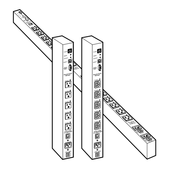
To access the Remote Power Manager via the Web-browser interface, assign an Internet IP address to the Remote Power Manager. Then type in the IP address in your Internet browser. You will be asked to enter a user name and password. (This password uses basic 64-bit encryption techniques to ensure secure access to your equipment.) Finally, a Web-browser interface screen will appear. - Page 18 NOTE Section 5.3.1 describes how to disable the manual switch button. ➁ Ready indicator: This LED flashes when the Remote Power Manager is ready to receive commands. ➂ Activity indicator: This LED flashes to indicate activity at the network port.
-
Page 19: Remote Power Manager, Remote Power Manager
➇ Power inlet: This IEC-320, 115-VAC inlet (PS565A) or 105- to 240-VAC inlet (PS565AE) supplies power for the Remote Power Manager’s command functions and the switched plug. It includes a cable keeper (not shown). ➈ Circuit breaker: 115 VAC, 15 amps (PS565A) or 230 VAC, 10 amps (PS565AE). - Page 20 CHAPTER 3: Overview ➀ Manual switch button: A control button for the Remote Power Manager 16’s switched plugs. To manually switch the plugs “On” or “Off,” press and hold the button for one second. NOTE Section 5.3.1 describes how to disable the manual switch button.
-
Page 21: Installation
Connect the power cord from up to five or sixteen switched devices to the switched AC outlets (#6 in Figure 3-1; #7 in Figure 3-2) on the Remote Power Manager. When power is applied to the Remote Power Manager, the switched AC outlets will be switched on. -
Page 22: Console Port Connection
When connecting directly to an external modem, use a standard null-modem cable. Make certain that the modem is initialized at the same default communications parameters as the Remote Power Manager’s console port. Next, refer to Section 5.3.1 and set the serial port mode to “Modem.” If necessary, redefine the modem initialization command as described in Section 5.3.1. -
Page 23: Connecting The Network Cable
The network port (#4 in Figures 3-1 or 3-2) is an RJ-45 Ethernet jack that connects to a TCP/IP network. Connect your 10BASE-T cable to the network port. The Remote Power Manager includes a default IP address (192.168.168.168) and a default subnet mask (255.255.255.0). When installing the Remote Power Manager in a working network environment, define network parameters as described in Section 5.3.4. -
Page 24: Configuration
The Remote Power Manager will display a password prompt when the unit is contacted via the console port or network port. The password you enter at this prompt determines whether the Remote Power Manager will start up in system mode or user mode. -
Page 25: Communicating With The Remote Power Manager
5.2 Communicating with the Remote Power Manager In order to configure the Remote Power Manager or invoke command functions, you must first install the Remote Power Manager (see Chapter 4) and access the operating mode. Choose either system or user mode (see Section 5.1). For either mode, the Remote Power Manager offers two separate operating-mode interfaces: the Web-browser interface and the text interface. - Page 26 CHAPTER 5: Configuration Figure 5-1. Plug Status screen—Web-browser interface for PS565A and PS565AE. Figure 5-2. Plug Status screen—Web-browser interface for PS567A.
-
Page 27: Accessing The Operating Mode Via The Text Interface
To access operating mode via the text interface: 1. The Remote Power Manager is transparent to parity and will accept 7- or 8-bit characters, but will always answer back at 8 bits, no parity. Make certain that your communication program is set for the appropriate baud rate, bits, parity, and comm port. - Page 28 Remote Power Manager via the text interface. NOTE The password feature is case sensitive. 3. If you enter a valid system or plug password, the Remote Power Manager displays the Plug Status screen shown in Figures 5-3 or 5-4, followed by the RPM> command prompt.
-
Page 29: Configuration Menus
5.3 Configuration Menus As described in the sections that follow, you can select configuration parameters for the Remote Power Manager via the Web-browser interface or text interface. Although the Web-browser and text interfaces provide two separate means for selecting parameters, both interfaces allow access to essentially the same set of parameters, and parameters you select via one interface will also apply to the other. -
Page 30: General Parameters Menus
CHAPTER 5: Configuration For the text interface, refer to the Help screen (/H) and then enter the appropriate command to access the desired menu. When the configuration menu appears, type in the number or letter for the parameter that you want to define. Follow the instructions in the resulting submenu. - Page 31 REMOTE POWER MANAGER, REMOTE POWER MANAGER 16 Figure 5-5. General Parameters menu—Web-browser interface for the PS565A and PS565AE. Figure 5-6. General Parameters menu—Web-browser interface for the PS567A.
- Page 32 For the text interface, type /G and press [Enter]. The General Parameters menu appears as shown in Figures 5-7 or 5-8. GENERAL PARAMETERS: System Password: (defined) User Name: Black Box Site ID: Black Box, Lawrence, PA Serial Port Mode: Console Modem Init. String: ATE0M0Q1&C1&D2S0=1 Baud Rate: 9600, N, 8, 1 Command Echo:...
- Page 33 PS565A and PS565AE or four to 16 characters long for the PS567A. The default password is “undefined.”) NOTES If the system password is not defined, then the Remote Power Manager always starts up in system mode, and configuration functions are then available to anyone who accesses operating mode.
- Page 34 • Command echo. Enables or disables command echo. When enabled, ASCII commands sent via the text interface to the Remote Power Manager echo back, displaying keystrokes. This feature applies primarily to the text interface and has no visible effect on the Web-browser interface.
-
Page 35: Serial (Console) Port Parameters Menus (Ps567A Only)
• Command prompt (PS567A). Selects the prompt that is sent when the Remote Power Manager is contacted via the text interface. The default prompt is RPM. • Default parameters. Resets the Remote Power Manager to default parameters. All menu-selected parameters, including port names and passwords, are cleared. - Page 36 CHAPTER 5: Configuration For the text interface, type /C and then press [Enter] . The Serial Parameters menu appears as shown in Figure 5-10. SERIAL PARAMETERS: 1. Baud Rate: 9600 2. Data: 8 Bit 3. Parity: None 4. Stop: 1 Bit 5.
-
Page 37: Plug Parameters Menus
ARAMETERS ENUS The Plug Parameters menus define plug names, plug passwords, and boot/sequence delay times for each of the Remote Power Manager’s five or sixteen switched AC outlets. For the Web-browser interface, click on the Setup button to access the configuration menus, then click on the Plug Parameters button. - Page 38 CHAPTER 5: Configuration Figure 5-12. Plug Parameters menu—Web-browser interface for PS567A. For the text interface, type /P n (where n is the plug number or name that you want to configure) and then press [Enter] . The Plug Parameters menu appears as shown in Figure 5-13.
- Page 39 • Plug password. Assigns a password to the corresponding plug. When you enter this password at login, you can issue commands to this plug and any other Remote Power Manager plug that shares the same password as described below. NOTE This password does not allow access to configuration functions.
- Page 40 4. Turn on plug 4, wait 1 minute. 5. Turn on plug 5. If a reboot command is applied to plug 3, the Remote Power Manager responds as follows: Turn off plug 3, wait 5 seconds, turn on plug 3.
-
Page 41: Network Parameters Menus
REMOTE POWER MANAGER, REMOTE POWER MANAGER 16 3. Wait 2 seconds, turn on plug 2, wait 2 seconds. 4. Wait 5 seconds, turn on plug 3, wait 5 seconds. 5. Wait 1 minute, turn on plug 4, wait 1 minute. - Page 42 CHAPTER 5: Configuration Figure 5-15. Network Parameters menu—Web-browser interface for PS567A. For the text interface, type /N and press [Enter]. The Network Parameters menu appears as shown in Figure 5-16. NETWORK PARAMETERS: 1. IP Address: 65.106.93.103 2. Subnet Mask: 255.255.255.0 3.
- Page 43 Web-browser interface and the text interface. • IP address. Defines the Remote Power Manager’s IP address. (The default IP address is 192.168.168.168.) • Subnet mask. Defines the Remote Power Manager’s subnet mask.
- Page 44 IP Security Feature Use the IP security feature to restrict unauthorized IP addresses from establishing a connection with the Remote Power Manager. In the default state, the Remote Power Manager accepts incoming IP connections from all hosts. To configure the IP security feature: 1.
- Page 45 Mask #5 has priority over the other four masks. If mask #5 is set to deny access by “255.255.255.255” (all wild cards), you can’t access the Remote Power Manager’s operating mode via a network. Access will only be allowed via a local PC or external modem connected to the Remote Power Manager’s console port.
-
Page 46: Telnet Parameters Menus
CHAPTER 5: Configuration 5.3.5 T ELNET ARAMETERS ENUS The Telnet Parameters menus enable/disable Telnet access to the Remote Power Manager operating mode and select the TCP port for Telnet connections. For the Web-browser interface, click on the Setup button to access the configuration menus, then click on the Telnet Parameters button to display the menu shown in Figure 5-18. -
Page 47: Web Server Parameters Menus
ARAMETERS ENUS The Web Server Parameters menus configure the Remote Power Manager’s internal Web server, which lets you operate the Remote Power Manager via the Web-browser interface. For the Web-browser interface, click on the Setup button to access the configuration menus, then click on the Web Server Parameters button. The Web Server Parameters menu appears as shown in Figure 5-20. -
Page 48: Save Configuration Parameters
Remote Power Manager via Telnet. (The default port number is 80.) 5.4 Save Configuration Parameters The Remote Power Manager offers two methods for saving parameters: saving to memory and saving to an ASCII file. Saving parameters to memory ensures that your user-defined configuration remains intact if power to the Remote Power Manager is temporarily interrupted. - Page 49 Manager. At this point, you can save new parameters to memory, continue without saving, or revert to previously saved parameters. If parameters are not saved, and if power to the Remote Power Manager is interrupted, newly defined parameters are lost. When power is restored, the Remote Power Manager is then configured with the previously saved parameters.
-
Page 50: Operation
Plug Status screen, which also displays the status of the Remote Power Manager’s five or sixteen switched outlets. When you log onto the Remote Power Manager operating mode using the Web- browser interface, the first screen that appears after login is the Plug Status menu. - Page 51 REMOTE POWER MANAGER, REMOTE POWER MANAGER 16 Figure 6-1. Plug Status menu—Web-browser interface for PS565A and PS565AE. Figure 6-2. Plug Status menu—Web-browser interface for PS567A.
- Page 52 To switch all plugs on, click the On button in the “All Plugs” row, then click on Apply. b) The Remote Power Manager displays a screen that indicates that the switching operation is in progress. It then returns to the updated Plug Status menu (which should now show the selected plugs in the On position).
-
Page 53: Operation Via The Text Interface
ASCII commands display status screens and allow you to log out of operating mode. The text interface also includes a Help menu, which summarizes all available Remote Power Manager commands. To display the text interface Help menu (Figures 6-3 or 6-4), type /H and press [Enter]. -
Page 54: The Plug Status Screen
TATUS CREEN When you login to the Remote Power Manager operating mode using the text interface, the first screen that appears after login is the Plug Status screen. The Plug Status screen (Figures 6-5 or 6-6) lists the current status of the Remote Power Manager’s switched AC outlets and displays the firmware version and currently... - Page 55 REMOTE POWER MANAGER, REMOTE POWER MANAGER 16 Remote Power Manager v1.10 Site ID: Black Box – Lawrence, PA Plug | Name | Password | Status | Boot/Seq. Delay ------------------------------------------------------------ | Server_1 | (defined) | ON | 1 Sec | Server_2...
-
Page 56: Boot/On/Off Commands
Users who log into operating mode using a plug password are only allowed to issue commands to the plugs permitted by that password. If command confirmation is enabled, the Remote Power Manager displays the status screen after the boot/on/off commands are successfully completed. -
Page 57: Applying Commands To Several Plugs
Power Manager has completely exited from operating mode and is not waiting for the inactivity timeout period before allowing additional connections. This ensures that the Remote Power Manager is available to other users and they will not have to wait for the timeout period before accessing the Remote Power Manager’s... -
Page 58: The Automated Mode
The automated mode allows the Remote Power Manager to execute switching and reboot commands without displaying menus or generating response messages. Automated mode allows the Remote Power Manager to be controlled by a device that can generate commands to control power-switching functions without human intervention. -
Page 59: Manual Operation
6.5 Manual Operation In addition to the command-driven functions available via the Web-browser interface and text interface, the Remote Power Manager’s switched plugs can also be toggled on and off manually. To manually toggle plugs on or off, press the manual switch button and hold it down for approximately three seconds. -
Page 60: Saving And Restoring Configuration Parameters
3. When the communications program is ready to receive the file, return to the Remote Power Manager’s operating mode, and press [Enter] to proceed. 4. The Remote Power Manager sends a series of ASCII command lines that specify the currently selected parameters. -
Page 61: Restoring Saved Parameters
If the console port is active, the baud rate, parity, data bits, and stop bits settings will not be changed until you disconnect from the console port. At this point, saved parameters are restored to the Remote Power Manager. Check the Plug Status screen, General Parameters menu, Plug Parameters menu, and Network Parameters menu to make certain that saved parameters are accurately restored. -
Page 62: Upgrading Firmware
4 and press [Enter] to abort the upgrade procedure. 4. Set your communication program for ASCII mode, then use the program’s Send File function to transfer the upgrade file to the Remote Power Manager. Select ASCII format, then specify the filename and directory location where... - Page 63 REMOTE POWER MANAGER, REMOTE POWER MANAGER 16 5. If the upload is successful, the Remote Power Manager will load the upgrade firmware into memory and then reboot itself. NOTE If you are performing the upgrade procedure via the network port, the Remote Power Manager will break the network connection when the system is reinitialized.
Need help?
Do you have a question about the Remote Power Manager and is the answer not in the manual?
Questions and answers