Cub Cadet Z-Force S Operator's Manual
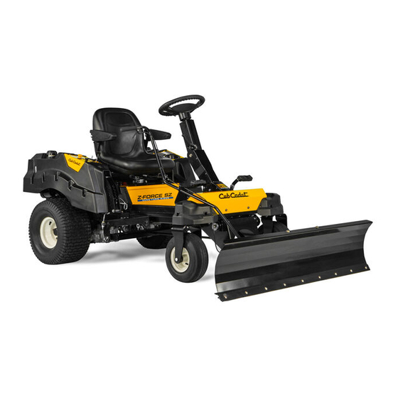
58” snow blade
Hide thumbs
Also See for Z-Force S:
- Operator's manual (40 pages) ,
- Service manual (34 pages) ,
- Limited warranty (1 page)
Advertisement
Safe Operation Practices • Set-Up • Operation • Maintenance • Service • Troubleshooting • Warranty
O
'
M
peratOr
s
anual
Z-Force S / PRO 100 58" Snow Blade
WARNING
READ AND FOLLOW ALL SAFETY RULES AND INSTRUCTIONS IN THIS MANUAL
BEFORE ATTEMPTING TO OPERATE THIS MACHINE.
FAILURE TO COMPLY WITH THESE INSTRUCTIONS MAY RESULT IN PERSONAL INJURY.
CUB CADET LLC, P.O. BOX 361131 CLEVELAND, OHIO 44136-0019
Form No. 769-09704C
(June 5, 2017)
Advertisement


Need help?
Do you have a question about the Z-Force S and is the answer not in the manual?
Questions and answers