
Related Manuals for Red Jacket CoreDEF Series


Summary of Contents for Red Jacket CoreDEF Series
- Page 1 Manual No: 577014-360 Revision: E ● CoreDEF Series Submersible DEF Pump Installation, Service, & Parts Lists...
- Page 2 For the parts return procedure, please follow the instructions in the “General Returned Goods Policy” pages of the “Policies and Literature” section of the Veeder-Root North American Red Jacket Mechanical Products Price Book. Veeder-Root will not accept any return product without a Return Goods Authorization (RGA) number clearly printed on the outside of the package.
-
Page 3: Table Of Contents
Table of Contents Introduction Overview ...........................1 Notes To Contractor/Installer ....................2 Recommended BulkHead And Manway Cover Openings........2 Safety Precautions ......................3 Warnings and Instructions ....................4 Preliminary Precautions....................4 Requirements For Use .....................4 Installation Environment ...................5 Cleanliness Of Surfaces In Contact With DEF ............5 Safety Instructions ....................5 Pump Dimensions ......................6 Kits And Accessories ......................7... - Page 4 Table of Contents Figure 10. Tie Strap UMP Cable To Column Piping (Shown W/Fixed Pressure Relief Assembly) .............13 Figure 11. Fixed Pressure Relief Installation Example ..........14 Figure 12. Adjustable Pressure Relief Installation Example ........15 Figure 13. Setting Optional Adjustable Relief Valve Pressure .......16 Figure 14.
-
Page 5: Overview
Introduction Overview The CoreDEF Series Submersible DEF Pump, herein referred to as Submersible DEF pump, is only intended to be used to pump Diesel Exhaust Fluid (DEF) from underground storage tanks (UST) or above ground totes in retail, commercial, and industrial applications. The submersible DEF pump installs into a threaded opening in the bulk head with a minimum diameter of 8”... -
Page 6: Notes To Contractor/Installer
Notes To Contractor/Installer Notes To Contractor/Installer Some considerations may be needed prior to specifying the Red Jacket Submersible DEF pump and it’s accessories/options. The system may be purchased with either an in-tank, fixed pressure relief or the adjustable pressure relief which is installed in the sump. -
Page 7: Safety Precautions
Remove spilled liquid and dispose of it in an environmentally sound man- WARNING The Red Jacket Submersible DEF Pump and wiring shall not be installed within a hazardous environment as defined by NFPA 70 (NEC). FAILURE TO COMPLY WITH THE FOLLOWING WARNINGS AND SAFETY PRECAUTIONS COULD CAUSE DAMAGE TO PROPERTY, ENVIRONMENT, RESULTING IN SERIOUS INJURY OR DEATH. -
Page 8: Warnings And Instructions
Introduction Warnings and Instructions Warnings and Instructions WARNING This section introduces the hazards and safety precautions associated with installing, inspecting, maintaining or servicing this product. Before performing any task on this product, read this safety information and the applicable sections in this manual, where additional hazards and safety precautions for your task will be found. -
Page 9: Installation Environment
Introduction Warnings and Instructions INSTALLATION ENVIRONMENT WARNING The submersible DEF pump is only intended to be used to pump DEF fluid. CLEANLINESS OF SURFACES IN CONTACT WITH DEF All surfaces in direct contact with DEF shall be free of foreign matter (fuel, oil, grease, detergent, dust and any other substance). -
Page 10: Pump Dimensions
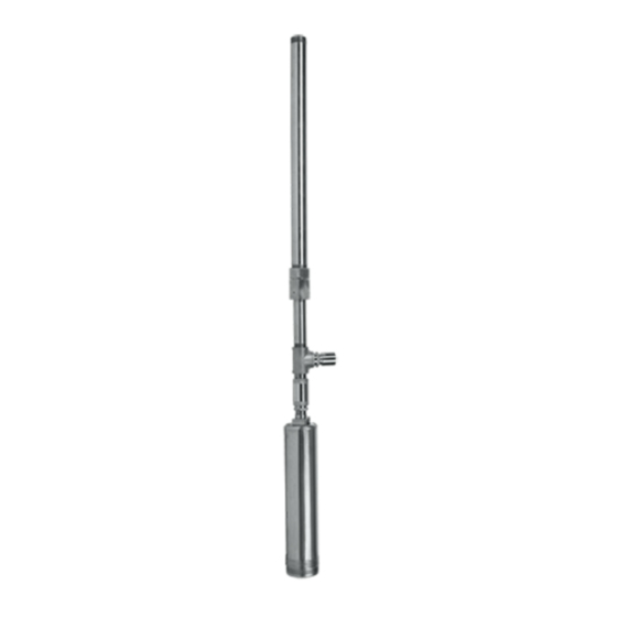
Introduction Pump Dimensions Pump Dimensions Figure 3 shows reference dimensions/components of a typical submersible DEF pump as installed with a fixed pressure relief. Figure 4 shows reference dimensions/components of a typical submersible DEF pump as installed with adjustable pressure relief. Optional Bottom of UMP to bottom... -
Page 11: Kits And Accessories
Introduction Kits And Accessories Bottom of UMP to bottom of bulk head ITEM DESCRIPTION Nipple - Hex 1.25” SST Reducer Bushing UMP Cable Zip Ties 1-1/2” Pipe Clinch Fitting Ass’y. 2” Pipe Manway 1/2” NPT Strain Relief w/customer MIN. 6” SUBMERSION supplied reducing bushing as required MIN. - Page 12 Introduction Kits And Accessories Select UMP (HP and voltage requirements Model Length Part Number Number Volts Phase (‘B’ Figure 3) Weight 410852-001 DP75U1 16.81” (427mm) 22 lbs. (10kg) 410852-002 DP75U3 16.81” (427mm) 22 lbs. (10kg) 410852-003 DP200U1 23.94” (608mm) 34.2 lbs. (15.5kg) 410852-004 DP200U17 23.94”...
- Page 13 Introduction Kits And Accessories 4. Select the Control Box for each pump. UMP (Capacitor or Heater) DP75U1, DP75U3-3 DP200U1 DP200U17 DP200U4 Dispenser Hook (17.5 F) (40 F) Voltage (CR123C526A) (CR123C867A) 120V hook 880-045-5 410861-001 ------- -------- Single Phase Control Box With Capacitor 240V hook 410860-003...
-
Page 14: Temperature Data
Introduction Temperature Data Item Part Number Description Adjustable Pressure Relief Valve w/1” NPT inlet/outlet Adjustable Pres- 410881-001 sure Relief Kit Check Valve* 410875-001 * NOTE: Check valve recommended with use of Adjustable Pressure Relief valve which is not designed to hold system pressure. -
Page 15: Installation
Installation Submersible DEF Pump Assembly If no column pipe assembly or fixed pressure relief valve was purchased it is mandatory the NOTICE contractor follow the ISO 22241 guidelines. Pressure relief must be used with all systems to limit discharge pressure to 50 psi (344.7 kPa). Any fixed length plumbing needs to allow for proper clearance to bottom of tank per Figure 3. -
Page 16: Figure 6. Measuring Tank
Installation Installing the Pump Top of manway Figure 6. Measuring Tank 3. Apply primer and coat sealant on threads of 1-1/4” SST hex nipple and hand screw UMP onto column pipe assembly. Place a pipe wrench over the rectangular cable holding bracket at the top of the UMP and a wrench on the hex faces of the nipple, tighten to 125 ft-lbs (170 N•m). -
Page 17: Figure 8. Loosening Locking Nut
Installation Installing the Pump A slight twisting of the UMP will loosen the seals and facilitate adjusting it to the correct NOTICE length. Do not rotate piping beyond 1/4 turn. 1/4 turn maximum on piping Figure 8. Loosening Locking Nut 6. -
Page 18: Typical Fixed Pressure Relief Installation
Installation Installing the Pump TYPICAL FIXED PRESSURE RELIEF INSTALLATION See example installation in Figure 11. No additional thermal relief is needed when using fixed pressure relief when located NOTICE downstream of check valve. UMP cable strain relief Sump DEF discharge line to dispensers Ball valve Return flow piping... -
Page 19: Adjustable Pressure Relief Option
Installation Installing the Pump ADJUSTABLE PRESSURE RELIEF OPTION If the fixed pressure relief kits are not ordered it is mandatory to install the adjustable pressure relief valve in the sump. This valve is a 1” NPT fitting and will need to follow the same guidelines for material compatibility and sealant. -
Page 20: Electrical Connections
Installation Electrical Connections 2. Remove the machined 1-1/8” hex cover from the end of the Adjustable Pressure Relief valve. 3. Adjust the set screw with the 1/4” hex key per Figure 13. Insert hex key into indent of pressure adjustment screw to set the relief pressure. -
Page 21: Simplified Wiring Diagrams
Installation Wiring Diagrams SIMPLIFIED WIRING DIAGRAMS Black Black Grey Grey Brown Brown Class 10 Yellow/ M1 - Main Yellow/Green Starter With Green M2 - Common Overloads M3 - Auxilliary C - Capacitor T - Thermal Device Figure 14. Single Phase Wiring Diagram Figure 15. -
Page 22: Capacitor (Models 880-045-5 Or 410861-001)
Installation Wiring Diagrams Load center 208/230 V, 1 Phase, 2 Wire DISCONNECT, LOCK OUT, WARNING AND TAG POWER AT THE POWER PANEL BEFORE WIRING THE PUMP. 15 amp 2 pole switch Continuous Cable Strain duty capacitor Relief Wiring trough Brown Grey Black Green... - Page 23 Installation Wiring Diagrams DISCONNECT, LOCK OUT, WARNING 240 VOLT AND TAG POWER AT THE LINE STARTER 25 WATT MAX. POWER PANEL BEFORE PILOT LIGHT WIRING THE PUMP. PILOT LIGHT 3 P.S.T. TOGGLE SWITCH LOAD CENTER PH N 220 OR 240 VOLT CAPACITOR Dispenser NOTICE...
- Page 24 Installation Wiring Diagrams DISCONNECT, LOCK OUT, WARNING AND TAG POWER AT THE POWER PANEL BEFORE LOAD CENTER PILOT LIGHT WIRING THE PUMP. 220 OR 240 VOLT 3P S.T. TOGGLE 1 PHASE, 2 WIRE SWITCH 15A-2P SWITCHED LINE NEUTRAL BREAKER STARTER PHASE NEUTRAL EXTERNAL PILOT...
- Page 25 Installation Wiring Diagrams NOTE: Starter is wired to NOTE: Starter is wired to 120 V Coil 240 V Coil 208/240V to pump motor, 208/240V to pump motor, 120 V to dispenser switch. 208/240 V to dispenser switch. To 208/240 V Supply To 208/240 V Supply Dispenser Dispenser...
- Page 26 Installation Wiring Diagrams DISCONNECT, LOCK OUT, WARNING ISOTROL CONTROL BOX (P/N 880-049-1) AND TAG POWER AT THE POWER PANEL BEFORE WIRING THE PUMP. UNSWITCHED NEUTRAL TO TB2 PHASE ON L1 MUST BE SAME AS DEVICE CONNECTED TO ATG TERMINAL NEUTRAL 1 2 3 4 5 6 7 8 DISPENSER INPUTS ATG S...
- Page 27 Installation Wiring Diagrams DISCONNECT, LOCK OUT, WARNING ISOTROL CONTROL BOX (P/N 880-050-1) AND TAG POWER AT THE POWER PANEL BEFORE WIRING THE PUMP. UNSWITCHED NEUTRAL TO TB2 PHASE ON L1 MUST BE SAME AS DEVICE CONNECTED TO ATG TERMINAL NEUTRAL 1 2 3 4 5 6 7 8 DISPENSER INPUTS ATG S...
- Page 28 Installation Wiring Diagrams WARNING DISCONNECT, LOCK OUT, ISOTROL CONTROL BOX (P/N 880-050-1) AND TAG POWER AT THE POWER PANEL BEFORE WIRING THE PUMP. UNSWITCHED NEUTRAL TO TB2 PHASE ON L1 MUST BE SAME AS DEVICE CONNECTED TO ATG TERMINAL NEUTRAL 1 2 3 4 5 6 7 8 DISPENSER INPUTS ATG S...
- Page 29 Installation Wiring Diagrams WARNING DISCONNECT, LOCK OUT, ISOTROL CONTROL BOX (P/N 880-049-1) AND TAG POWER AT THE POWER PANEL BEFORE WIRING THE PUMP. UNSWITCHED NEUTRAL TO TB2 PHASE ON L1 MUST BE SAME AS DEVICE CONNECTED TO ATG TERMINAL NEUTRAL 1 2 3 4 5 6 7 8 DISPENSER INPUTS ATG S...
- Page 30 Installation Wiring Diagrams WARNING DISCONNECT, LOCK OUT, ISOTROL CONTROL BOX (P/N 880-047-1) AND TAG POWER AT THE POWER PANEL BEFORE OUTPUT FROM WIRING THE PUMP. TO CIRCUIT CIRCUIT UNSWITCHED NEUTRAL TO TB2 RELAY NEUTRAL 1 2 3 4 5 6 7 8 DISPENSER INPUTS ATG S CHANNEL 1...
-
Page 31: (Models 410860-001 Or 410860-003)
Installation Wiring Diagrams WARNING DISCONNECT, LOCK OUT, ISOTROL CONTROL BOX (P/N 880-048-1) AND TAG POWER AT THE POWER PANEL BEFORE OUTPUT FROM WIRING THE PUMP. TO CIRCUIT CIRCUIT UNSWITCHED NEUTRAL TO TB2 RELAY NEUTRAL 1 2 3 4 5 6 7 8 DISPENSER INPUTS ATG S CHANNEL 1... - Page 32 Installation Wiring Diagrams WARNING DISCONNECT, LOCK OUT, ISOTROL CONTROL BOX (P/N 880-048-1) AND TAG POWER AT THE POWER PANEL BEFORE OUTPUT FROM WIRING THE PUMP. TO CIRCUIT CIRCUIT UNSWITCHED NEUTRAL TO TB2 RELAY NEUTRAL 1 2 3 4 5 6 7 8 DISPENSER INPUTS ATG S CHANNEL 1...
- Page 33 Installation Wiring Diagrams WARNING DISCONNECT, LOCK OUT, ISOTROL CONTROL BOX (P/N 880-047-1) AND TAG POWER AT THE POWER PANEL BEFORE OUTPUT FROM WIRING THE PUMP. TO CIRCUIT CIRCUIT UNSWITCHED NEUTRAL TO TB2 RELAY NEUTRAL 1 2 3 4 5 6 7 8 DISPENSER INPUTS ATG S CHANNEL 1...
-
Page 34: Operational Precautions
Installation Operational Precautions Operational Precautions • Pump must be completely submerged in DEF (primed) prior for initial install to avoid a dry start condition. • Do not allow pump to run dry or damage will occur. • DEF freezes at approximately 12°F (-11°C). •... -
Page 35: Troubleshooting
Troubleshooting Table 2. Submersible DEF Pump System Troubleshooting Trouble Cause Corrective Action a. Incorrect voltage or volt- a. Check the voltage during starting. If the wiring cross- age drop. section is too small, the voltage drop may be such that the motor cannot function normally. -
Page 36: Table 3. Pressure Expectations By Pressure Relief Type
Troubleshooting Maintenance Table 3. Pressure Expectations By Pressure Relief Type Pump Off Pump On Fixed Adjustable Fixed Adjustable 3/4 HP 28 psi 45 psi 310.3 As Set (193.1 kPa) kPa) 2 HP Pump-Off pressure expectations for adjustable pressure relief type are only 0 psi upstream NOTICE of check valve. -
Page 37: General Repair
General Repair WARNING Disconnect, lock out, and tag power at the panel before servicing the pump. If a system has any issues found during the troubleshooting process follow the steps below: 1. Remove pressure from system. Ensure no DEF fluid is in the lines in the sump. 2. -
Page 38: Table 4. Recommended Torque Settings
General Repair Maintenance 10. See recommended torque settings for fittings in Table 4. Table 4. Recommended Torque Settings Item Torque All 1-1/4” NPT Fittings 125 ft-lbs (170 N•m) 2” NPT Column Pipe To Manway Cover Nipple 150 ft- lbs (203 N•m) Column Pipe Locking (Clinch) Nut 150 ft- lbs (203 N•m) Column Pipe Locking (Clinch) Nut Set Screw... -
Page 39: Parts Lists
Parts Lists Submersible Pump And Accessories Table 5. Replacement Parts Item Description DP75U1 410852-001 DP75U3 410852-002 DP200U1 410852-003 DP200U17 410852-004 DP200U4 410852-005 Pressure Relief Kit Adjustable Pressure Relief Kit 410881-001 Replacement Cable Cable Repair Kit 410886-001 3/4 HP Relief Valve Kit, 1/2” NPT 410882-001 2 HP Relief Valve Kit, 1-1/4”... -
Page 40: Control Boxes
Parts Lists Control Boxes Control Boxes Figure 32. Control Box W/Capacitor Table 7. Control Box W/Capacitor (120V Coil) 880-045-5 880-046-5 0410861-001 CB-3/4 HP CB-1-1/2 HP CB-2 HP Item Qty. / Part 17.5 µF 25 µF 40 µF (Refer Figure 32) Number Description 120V Coil... -
Page 41: Table 9. 880-041-5 / 880-042-5 Control Box
Parts Lists Control Boxes Table 8. Control Box W/Capacitor (240V Coil) 0410860-003 0410860-002 0410860-001 CB-3/4 HP CB-1-1/2 HP CB-2 HP Item 17.5 µF 25 µF 40 µF (Refer Figure 32) Qty./Part Number Description 240V Coil 240V Coil 240V Coil 247-001-5 Pilot Light Assy. - Page 42 For technical support, sales or other assistance, please visit: www.veeder.com...
Need help?
Do you have a question about the CoreDEF Series and is the answer not in the manual?
Questions and answers