Table of Contents
Advertisement
Advertisement
Table of Contents

Related Manuals for Redarc MANAGER 30


Summary of Contents for Redarc MANAGER 30
- Page 1 MANAGER Battery Management System BMS1230S3R...
-
Page 2: Warnings And Safety Instructions
REDARC for repair. Incorrect handling or reassembly may result in a risk of electric shock or fire and may void the unit warranty. Use of an attachment not recommended or sold by REDARC may result in a risk of fire, electric shock, or injury to persons. - Page 3 WARNINGS & SAFETY INSTRUCTIONS Do NOT try to charge non-rechargeable batteries with the Manager30. When using the Battery Charger to charge a Lithium Iron Phosphate battery, only batteries that feature an inbuilt battery management system featuring inbuilt under and over voltage protection and cell balancing are suitable. 10.
-
Page 4: Table Of Contents
CONTENTS Table of Contents Page Warnings and Safety Instructions Contents Features and Benefits 1 Introduction 1. General Description 2. The Display 3. The Kit Includes 4. Specifications 5. Multi-stage Charging Process 6. Maximum Charging Current Setting 7. Green Power Priority 2 INSTALLATION Guide 1. -
Page 5: Features And Benefits
It is manufactured with high- quality components to ISO9001 quality and ISO14001 environmental standards and backed with REDARC’s quality service and two-year warranty. 4. The Manager30 charging algorithm uses solar whenever possible making the unit more energy efficient and better for the environment. -
Page 6: Introduction
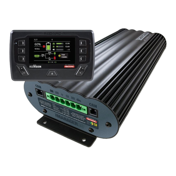
INTRODUCTION General Description The Manager30 is designed to offer a complete solution to battery charging and maintenance needs for recreational automotive applications. The Manager30 incorporates AC, DC and Solar inputs to achieve the best charge to a house battery. The Display The Manager30 comes with a Display designed to give you house battery information and charge status along with critical system information while charging is in progress. -
Page 7: Specifications
INTRODUCTION Specifications Electrical Specifications Inputs AC Input Input Voltage Range (nominal) 220-240VAC 50Hz Power Rating 560W Efficiency 80% - 90% Connection IEC Mains Plug DC Input Input Voltage Range 9 - 32V Turn ON/OFF Threshold 12V (24V) 13.2V/12.7V (26.4V/25.4V) Power Rating 520W Efficiency Connection... - Page 8 INTRODUCTION Figure 1.4.1 - Main Unit Dimensions 18.5 Optional Spacer 19 15 Figure 1.4.2 - Display Dimensions...
-
Page 9: Multi-Stage Charging Process
INTRODUCTION Multi-stage Charging Process The Manager30 incorporates two different multi-stage charging profiles – Touring (3-stage) and Storage (8-stage) – which can be selected in the System Mode menu (outlined in section 3.4 on page 28 of this manual) on the Display. Touring Mode Touring mode is designed for use when ‘on the road’. - Page 10 INTRODUCTION Storage Mode Storage mode is designed to charge the house battery to its optimal level and maintain that level while your caravan is in storage. This mode requires a valid charging source (240V or solar and all loads to be switched off or disconnected from the house battery before charging.
-
Page 11: Maximum Charging Current Setting
Recommended batteries Because of the rapidly changing nature of batteries and battery technology, REDARC avoid recommending specific battery makes or models. Instead, we recommend consultation with a battery specialist, and that the batteries used be UL approved where possible. -
Page 12: Installation Guide
INSTALLATION GUIDE System Layout Battery Sensor Solar Panels To Loads (Not Supplied) (Not Supplied) Vehicle Battery House Battery (Not Supplied) DC - DC (Not Supplied) Power Source Display BMS1230S3 240VAC Mains Power Figure 2.1.1 - System Layout Mounting Instructions This section describes how to mount the three major components of The Manager30: the Main Unit, the Display and the Battery Sensor. -
Page 13: Mounting The Main Unit
REDARC recommends that the Main Unit be mounted to optimise airflow past the heatsink. Mounting the unit horizontally (see Figure 2.2.1.1) is recommended and mounting vertically (see Figure 2.2.1.2) is still acceptable. -
Page 14: Mounting The Display
INSTALLATION GUIDE 2.2.2 Mounting the Display The Display should be mounted inside the vehicle (Refer to page 48 for a 1:1 cutout template). It is however acceptable to mount the Display in any convenient location, as long as it is protected from harsh environments such as being exposed to rain or severe amounts of dust or full-time direct sunlight. - Page 15 INSTALLATION GUIDE Removing the Display Fascia...
- Page 16 INSTALLATION GUIDE Refer to page 36 for a 1:1 cutout template Flush Mount Drill/Cut Dimensions NOT TO SCALE Refer to page 37 for a 1:1 cutout template Surface Mount Drill/Cut Dimensions NOT TO SCALE Refer to page 37 for a 1:1 cutout template Ø45mm...
-
Page 17: Mounting The Battery Sensor
The length of cables on the Battery Sensor to connect to the Main Unit and the House Battery will dictate the allowable mounting distance from the battery however REDARC recommend mounting the Battery Sensor as close to the House Battery as possible. - Page 18 INSTALLATION GUIDE Input Wire Diameter Selection REDARC recommends the installer use cabling and connections between 8B&S and 6B&S automotive. REDARC recommends that the input wire be of the size outlined in Table 2.3.1.1. Distance from input vehicle Recommended Cross Recommended battery to The Manager30 Sectional Area (mm²)
-
Page 19: The Manager30 Wiring Connections
INSTALLATION GUIDE The Manager30 Wiring Connections REDARC recommends that this unit be installed by a suitably qualified person. The AC power connection must be connected to an earthed socket outlet. Do not use The Manager30 AC input if the cord is damaged. Use of a non-genuine or damaged AC input cord may result in a risk of fire, electric shock, or injury to persons. -
Page 20: Connecting The Battery Sensor
INSTALLATION GUIDE 2.4.3 Connecting the Battery Sensor Wire the Battery Sensor as shown in Figure 2.4.3.1 ensuring that the “BNEG” stud connects to the House Battery negative terminal and the “GND” stud connects to the vehicle common ground point. The Battery Positive Lead connects to the house battery positive terminal, this lead measures voltage and temperature at the battery. - Page 21 INSTALLATION GUIDE...
-
Page 22: Batteries
INSTALLATION GUIDE Batteries Working in the vicinity of a Lead-Acid battery is dangerous. Batteries generate explosive gases during normal operation. For this reason, it is of utmost importance that you follow the instructions each time you use the charger. When charging a battery, make sure the settings at the Battery Setup menu on the Display are correct for the type of battery under charge. -
Page 23: Mppt Solar Regulator
INSTALLATION GUIDE MPPT Solar Regulator The Manager30 is designed for use with 12V solar panels. A minimum input voltage of 17.5V is required to start charging from a solar source. Once charging has started, the operating voltage range of the solar input can go as low as 9V and as high as 32V; outside of this range, charging will stop. -
Page 24: User Guide
USER GUIDE The Display Time Notification Bar 13.9V 13.6V 10 hrs ---V Softkeys Softkeys 150Wh Up/Down Left/Right arrow arrow Left/Right function Power Button The Display is the main user interface for the Manager30 System. The Display is designed to give you control of how the battery is being charged, as well as up-to-date house battery and charge information at any time during the charging process. - Page 25 USER GUIDE Navigation The Left/Right buttons are used to navigate the pages on the centre of the screen. The Up/Down buttons are used to navigate through options found on other pages or to cycle through devices on the Home Page when a Distribution Box is connected. The Left/Right and Up/Down functions are indicated on the screen.
-
Page 26: Basic Screens
USER GUIDE Basic Screens Home Screen When connected to a Manager only, 13.9V the RedVision display will provide 13.6V real time information on the battery 10 hrs ---V State of Charge, Sources, Current Flow and Solar Input Pushing Left reveals the Settings 150Wh menu and Right reveals the information menu. - Page 27 Pushing the down arrow displays When used with a REDARC MANAGER system. the Distribution Box Info. screen* When used with a REDARC RedVision Distribution Box. State of Charge logs The State of Charge log screens State of Charge per Day...
-
Page 28: Display Settings
USER GUIDE Display Settings Factory Settings Display Settings Key Sound: Key Backlight: Home Timeout: 1 min Standby Timeout: 1 min Brightness Minimum: Brightness Maximum: 100% Clock Format: 12 Hour The Display Settings screen allows setup and modification of Display specific settings as outlined below. -
Page 29: System Settings
REDARC This icon links to the RBus Diagnostics screen. This screen provides a serial number for each REDARC device connected to the system. More information on the selected device can be found by clicking the top right Soft Key This icon links to the Fault History screen. -
Page 30: Bms Settings
USER GUIDE BMS Settings BMS Settings When a Battery Management System is connected, the system will allow setup and modification of a number of BMS settings as outlined below. This icon will return to the Home Screen This icon links to the Battery Information screen. This screen allows the user to set their battery type and size. -
Page 31: Fault Display
USER GUIDE Fault Display Output battery over temperature. If The Manager30 detects a problem with the charging system that prevents it from continuing to charge the battery, it will alert you via a ‘Fault’ screen and an alarm buzzer, and will instantly terminate the charging cycle until the fault condition is cleared. The screen will give a brief description of the problem and will allow you to select either ‘Clear’... - Page 32 USER GUIDE Faults CHARGER FAULT MESSAGE CAUSE ACTION Charger over current fault An internal error has caused excessive Return to supplier current draw Charger over voltage fault The output voltage is too high (above Check battery is correct type (12V, 6 18V) cell) Charger over temperature.
-
Page 33: The Redvision App
However, the app has been designed to work with: • IOS 11. 1 (or later) • Android 7.0 (or later) and with • Bluetooth 4.0 (or later). ® For a full list of compatible devices as they become validated, please visit: www.redarc.com.au/redvision... - Page 34 Pairing Instructions ® 1. Install the RedVision or Configurator App (scan the corresponding QR code or search for “REDARC” on your device’s app store) 2. On the Display, press Left, navigate to display RedVision settings & press the Bluetooth ®...
- Page 35 USER GUIDE Subsequent Connections Once a smartphone has been paired with a RedVision Display, it will automatically reconnect with that Display when the app is opened. If you have multiple Redvision Displays paired and you want to switch between which is connected to your smart phone, tap on the 3 gear symbol on the top left of the app.
-
Page 36: Frequently Asked Questions
Q I have damaged my Power Cable and need to replace it, do I have to buy a special kind of cable. A To ensure the correct operation of The Manager30, REDARC advise that if the supply cord is damaged it must be replaced by a special cord available from the manufacturer. -
Page 37: Display Drill/Cutout Template
DISPLAY DRILL/CUTOUT TEMPLATE... -
Page 39: Two Year Warranty
• Friendly, personalised, professional service and product support In the unlikely event that a technical issue arises with a Redarc product, customers are encouraged to initially contact the Redarc Technical Support Team on (08) 8322 4848 power@redarc.com.au for prompt and efficient diagnosis and product support. - Page 40 +64-9-222-1024 North America power@redarcelectronics.com www.redarcelectronics.com United States +1 (704) 247-5150 Canada +1 (604) 260-5512 Mexico +52 (558) 526-2898 UK/Europe power@redarcelectronics.eu www.redarcelectronics.eu +44 (0)20 3930 8109 Copyright © 2019 REDARC Electronics Pty Ltd. All rights reserved. www.redarc.com.au WARBMS1230S3R - REV5...
Need help?
Do you have a question about the MANAGER 30 and is the answer not in the manual?
Questions and answers